Document overview
Digital Workshop Manual documentation for model DEUTZ FAHR 4080W from the Series 4W family. Language: English; 690 pages.
The corresponding English table of contents contains 43 sections and 241 individual topics.
Main sections included
- Introduction
- Safety
- Technical characteristics
- Calibrations and electronic diagnosis
- Method of intervention
- Wiring diagrams
- Service Info
Document details
- Brand: DEUTZ FAHR
- Family: Series 4W
- Model: 4080W
- Document type: Workshop Manual
- Language: English
- Pages: 690
- File size: 244.60 MiB
- Format: Digital PDF download
Compatibility
Before purchasing, verify that your machine model and reference code match DEUTZ FAHR 4080W.
Complete table of contents
Introduction
- Tightening torques
- Pump tightening torques
- Wheel nut/screw tightening torques
- Tightening torques for nuts and bolts of electrical connections
- Installation of solenoid valves and cartridge valves
- Installation of quick couplers
Safety
Preface
- Important notes concerning safety
Important safety information
- Recognising hazards
- Indications for persons in contact with the tractor
Safety rules
- Risks during tractor preparation
- Risks during maintenance
- Work on machine systems
- Special disassembly/assembly/inspection procedures
Safety pictograms
- Replacing safety pictograms
Environmental risks
- Hazards associated with the operating environment
Technical characteristics
Engine
- Diesel Engine
- Engine drive belt (without air conditioning compressor)
- Engine drive belt (with air conditioning compressor)
- Fuel System
- Technical characteristic parameters of engine
- Main tightening bolt torque of engine
Engine accessories
- Fuel Tank
- Cooling system
- Coolant radiator, fuel radiator and intercooler
Transmission
- Differential bearing
- Bevel Gear Shaft
- Transmission layout, transmission with planetary shuttle shifting
- Transmission layout, transmission with common shuttle shifting
- Transmission layout, 6+8 transmission with synchronizer
- Transmission section
Front axle
- Front axle
Hydraulic system
- Steering and auxiliary utilities hydraulic circuit
- Hydraulic system components
- Hydraulic system components
- Hydraulic system components
- Hydraulic system components -Configuration 2
- Hydraulic system components – Configuration 3
- Hydraulic steering
Electrical equipment
- Crankshaft and Camshaft Speed Sensor
- Elettronic control unit ECU
- Alternator
- List of fault code
Rear lift
- Rear lift box
- Rear lift cylinder
- Three-point linkage component
Calibrations and electronic diagnosis
Diagnostic tools
- HED diagnostic tool
- Diagnostic tool
- ECUs
Commissioning and calibrating the tractor
- Diagnostic port – OBD socket location
ECU alarms
- ECU ALARMS
Method of intervention
B0 – Engine
- Separating the complete engine
- Separating engine / transmission
- belt
- Flywheel
- Crankshaft assembly
- Replacing the front shock absorber assembly
- Piston and connecting rod assembly
- Push rod and rocker arm assembly
- Camshaft assembly
- Gear housing and gear
- Timing gear
- Replacing the cylinder head cover assembly
- Cylinder head
- Cylinder head assembly
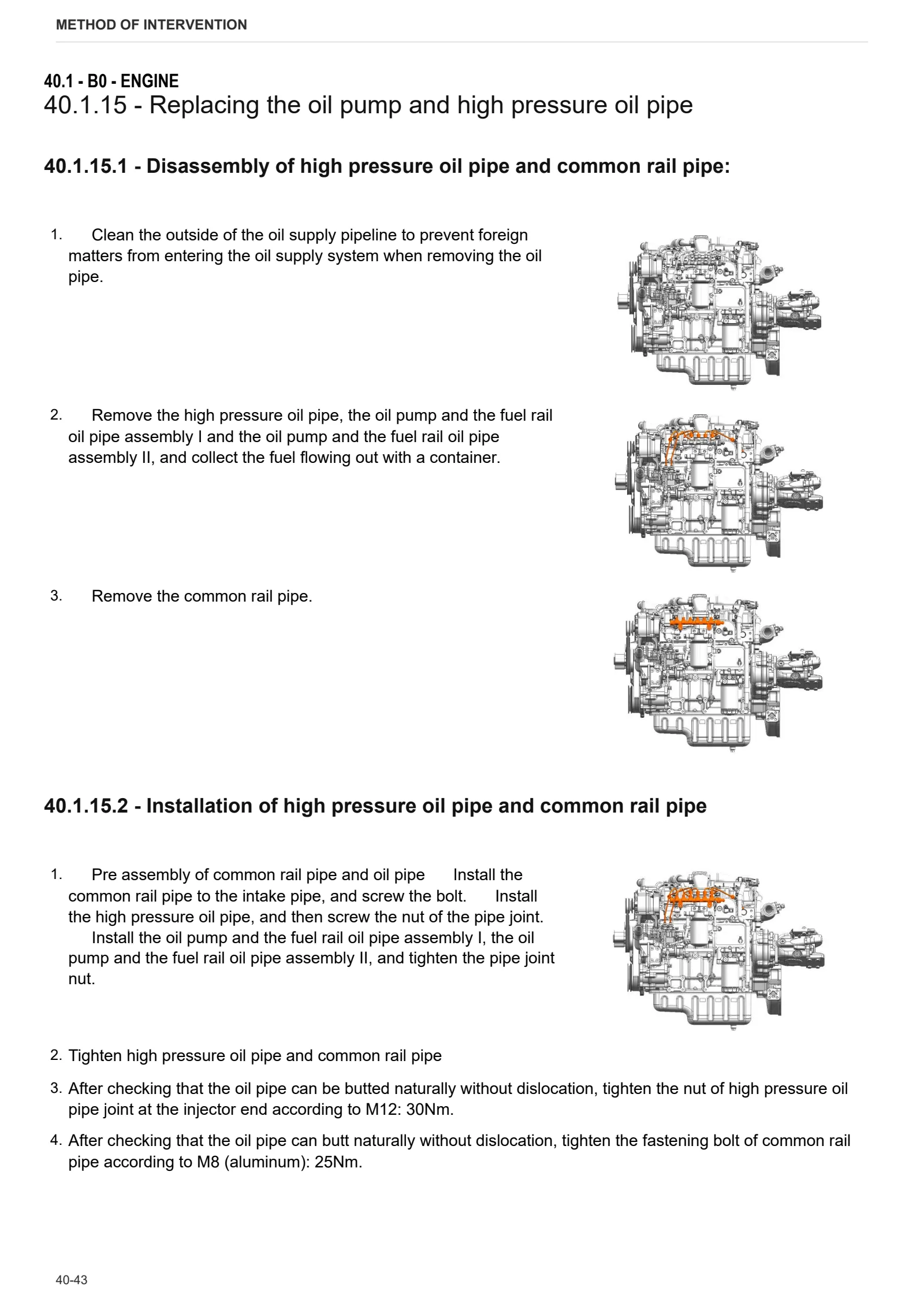
- Replacing the oil pump and high pressure oil pipe
- Replacing the oil cooler assembly
- Oil strainer
- Oil pump
- Replacement of diesel fine filter
- Replacing of the fuel injector
- Fuel injection pump assembly
- Fan, belt and tension pulley
C0 – Engine accessories
- Draining the coolant
- Fan
- Radiator assembly
- Compensation tank
- Air filter
- Rigid air filter pipe
- Air filter mounting bracket
- Diesel filter
- Fuel prefilter
- Fuel tank
- Air Exhaust from Fuel Supply System
- Starter motor
- Exhaust pipe
- Intermediate manifold
- Exhaust silencer
- Replacing the thermostat
- Replacing the water pump assembly
- Replacing the supercharger
- Replacing the starter motor
- Crankshaft sensor
- Water temperature sensor
- Replacing the oil pressure temperature sensor
- Intake pressure temperature sensor
- Replacing the generator
- Flywheel housing
- Flywheel
D0 – Transmission
- Changing the transmission oil
- Separating front gearbox housing from rear gearbox housing
- Gear cover
- Connector housing
- Clutch unit
- Clutch thrust bearing
- Disassembling the gearbox housing
- Shuttle unit
- Disassembling the reverse shuttle planetary reduction gearbox
- Parking brake
- 4WD engagement device
- 4WD shaft in gearbox casing
- Rear pinion casing
- Disassembling the rear pinion casing
- Gear, range and reverse shuttle selector rods inside gearbox
- PTO output shaft
- Disassembling the PTO output shaft
E0 – Rear axle
- Right-hand rear axle
- Left-hand rear axle
- Brake housing
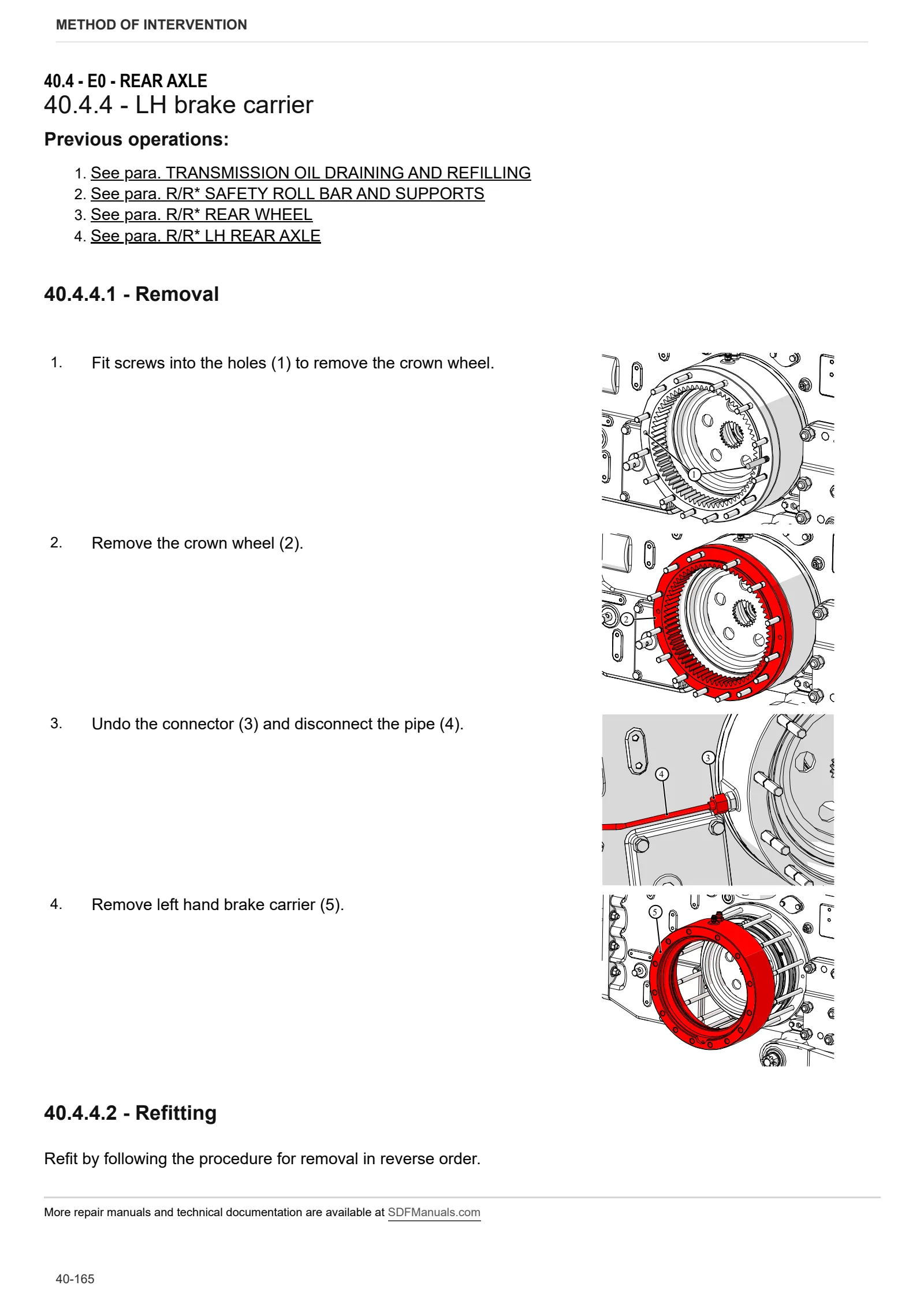
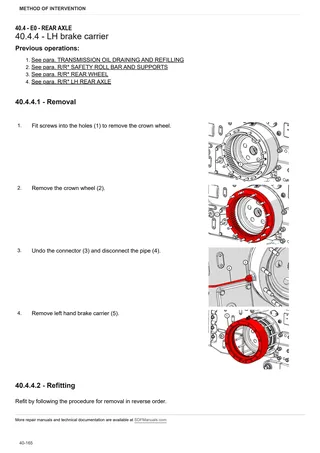
- LH brake carrier
- Disassembling rear axle
- Rear differential
- Removing rear differential
- Bleeding air from the hydraulic brake system
F0 – Front axle
- Front axle
- 4WD shaft
- Support with front axle
G0 – Bodywork – Cab – Platform
- Platform
- Engine hood
- Engine cowl front bracket and grille
- Lower hood guard
- Engine hood frame
- Battery mount
- Cab carrier brackets
- Instrument cluster
- Cab access steps
- Fan guard
- Turn indicators
- External rear-view mirrors
- Driver seat
- Handle
- Rear mudguard
- Toolbox
- Roll bar with roof
- Roof
- Roof with mount
- Throttle pedal
- 4WD (DT) selector lever
- Parking brake lever
- PTO on/off lever
- Gear and range selector lever
- PTO speed selector lever
- Differential lock pedal
- Clutch pedal
- Distributor and lift control lever assembly
- Disassembling the distributor and lift control levers
- Adjustment of free stroke of main clutch pedal
- Adjustment of Free Strokes of Auxiliary Clutch Control Handle
- Brake pedal
- Adjustment of Brake and Operating Mechanism
- Steering column
- Steering wheel
- Brake master cylinders
- Brake fluid reservoir
H0 – Hydraulic system
- Auxiliary utilities pump
- Orbitrol
- 4-way rear auxiliary utility distributor.
- Rear auxiliary utility distributor with bracket
L0 – Electrical system
- Battery
- Alternator
- Front lights
- Rear work lights
- Engine harness assembly
R0 – Rear lift
- Rear lift
- Adjustment of Hydraulic Hitch System
- 3-point linkage
S0 – Wheels
- Front Wheels
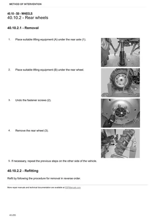
- Rear wheels
V0 – Ballast – towing hitches
- Drawbar
- Ballast weights and ballast carrier
- Tow hook
Wiring diagrams
Components
- A – Starting and charging
- B – Fuses
- C – Grounds
- D – Intermediate connections
- E – On-board instruments
- F – External lights (rotating beacon)
- H – Manual electrical controls (steering column stalk)
- I – Circuit breakers
- J – Relays
- K – Sensors and transmitters
- M – Electrical/electronic devices, Flasher units and Timers
- P – Various services
- R – Diagnostics
Systems
- S001 – Starting
- S002 – Sidelights and turn indicators
- S003 – High beam and low beam headlights
- S004 – Brakes and horn
- S005 – Instrument cluster
- S006 – Engine control
- S007 – Work lights
Wiring harnesses
- Wire colour reference table
- A11.48.012.3 – Front fuse box
- A11.48.022.0/10 – Central wiring loom
- A11.48.024.0/10 – Engine
- A11.48.027.0/10 – Engine ECU
- A11.48.028.0 – Utilities oil pressure switch
- A11.48.032.0 – Cab – transmission ground
- A11.48.037.0 – Front lights
- A11.48.033.0/10 – Rear lighting
- A11.48.042.0 – Battery positive
- A11.48.043.0 – Power feed
- A11.48.044.0 – Battery negative
- A85.48.109.0 – Battery master switch ground
- DF304.48.019/10 – Cowl
Service Info
A0 – TRACTOR
- Diagnostics 2026 subscription
- After-sales 2026 subscription
- SERVICE NEWS RESEARCH GUIDE
- Diagnostics 2025 subscription
- After-sales 2025 subscription
- Diagnostics 2023 subscription
- Diagnostics 2024 subscription
- Diagnostics 2022 subscription
- Diagnostics 2021 subscription
- After-sales 2024 subscription
- After-sales 2023 subscription
- After-sales 2022 subscription
- After-sales 2021 subscription
- After-sales 2019 subscription
- Diagnostics – 2020 subscription
- After-sales – 2020 subscription
B0 – ENGINE
- Deutz AG engine oil specifications
C0 – ENGINE ACCESSORIES
- Diagnostic protocol – AdBlue – Float level unit
- Filter and prefilter tool p/n 5.9035.865.0
- SCR AREA DAMAGED SENSORS
F0 – FRONT AXLE
- Bevel gear set loosing screws
- Check the front axle steering knuckles for wear
- Steering behavior check procedure
G0 – BODYWORK – CAB
- Air conditioning system recharging
H0 – HYDRAULIC AND PNEUMATIC SYSTEM|
- Hydraulic CUNA trailer braking kit (ITALY)
- Single connection hydraulic braking kit availability update – only for EUROPEAN market
L0 – ELECTRIC AL SYSTEM
- YUCHAI Electronic Diagnosis