Document overview
Workshop Manual PDF for SAME IRON 180, IRON family. Document language: English; 534 pages.
The corresponding English table of contents contains 26 sections and 142 individual topics.
Main sections included
- Introduction
- Safety
- Technical characteristics
- Method of intervention
- Service Info
Document details
- Brand: SAME
- Family: IRON
- Model: IRON 180
- Document type: Workshop Manual
- Language: English
- Pages: 534
- File size: 78.04 MiB
- Format: Digital PDF download
Compatibility
Before purchasing, verify that your machine model and reference code match SAME IRON 180.
Complete table of contents
Introduction
- Tightening torques
Safety
Preface
- Important notes concerning safety
Important safety information
- Recognising hazards
- Indications for persons in contact with the tractor
Safety rules
- Risks during tractor preparation
- Risks during maintenance
- Work on machine systems
- Special disassembly/assembly/inspection procedures
Safety pictograms
- Replacing safety pictograms
Environmental risks
- Hazards associated with the operating environment
Technical characteristics
Engine
- Technical data
- Valve clearance adjustment diagram
- Tightening sequence for cylinder head screws.
- Determining correct washer thickness for setting start of delivery angle
- Determining correct washer thickness for setting start of delivery angle, BFM 1012 engine
- Determining correct washer thickness for setting start of delivery angle, BFM 1013 engine
- Determining the overall size measurements
- Explanations of symbols
Transmission
- Transmission
- Rear PTO
Rear axle
- Rear axle
Front axle
- Front axle
- Front axle
- Front axle
Method of intervention
B0 – Engine
- Tools required
- Construction unit
- Compression pressure
- Engine reassembly – Intake elbow hose
- Engine reassembly – Boost air elbow hose
- Engine reassembly – Alternator
- Replacing the oil seals on the complete engine
- Disassembly and reassembly of PTO
- Ring gear/flywheel
- Engine disassembly
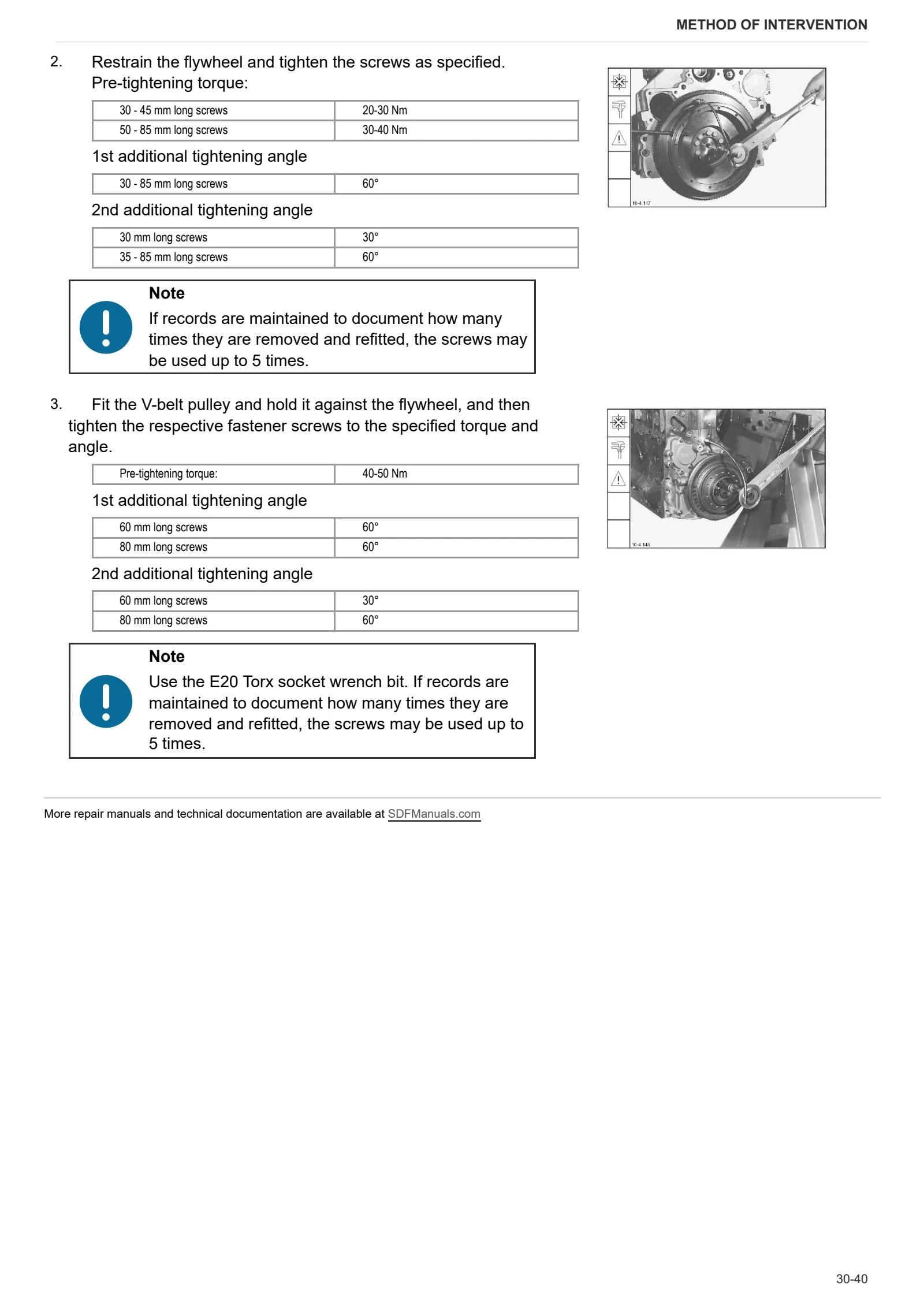
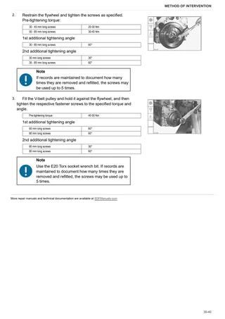
- Engine reassembly – Flywheel/V-belt pulley
- Cylinder block – Cylinders
- Front cover/Oil sump
- Engine reassembly – Timing case cover
- Engine reassembly – Tappet cover
- Engine reassembly – Turbocharger
- Engine reassembly – Oil return pipe/oil delivery pipe
- Crankshaft
- Connecting rod
- Piston
- Rocker carrier
- Oil cooler
- Fuel pump
- Injector
- Rack rod
- Thermostat
- Coolant pump
- Cooling fan
- Balancer weight shaft
- Cylinder heads
- Camshaft
- Timing case
C0 – Engine accessories
- Engine reassembly – Starter motor
- Air compressor
- Hydraulic pump drive
- Hydraulic pump with mounting flange
D0 – Transmission
- Changing the transmission oil
- Check the transmission oil level
- Changing the gearbox and rear axle oil filter
- Torsional spring plate
- Propeller shaft – Front axle drive shaft
- Separate transmission components
- Remove bearing cover
- Disassembl e clutch A/C
- Disassembly clutch B/D
- Disassemble clutch F/G
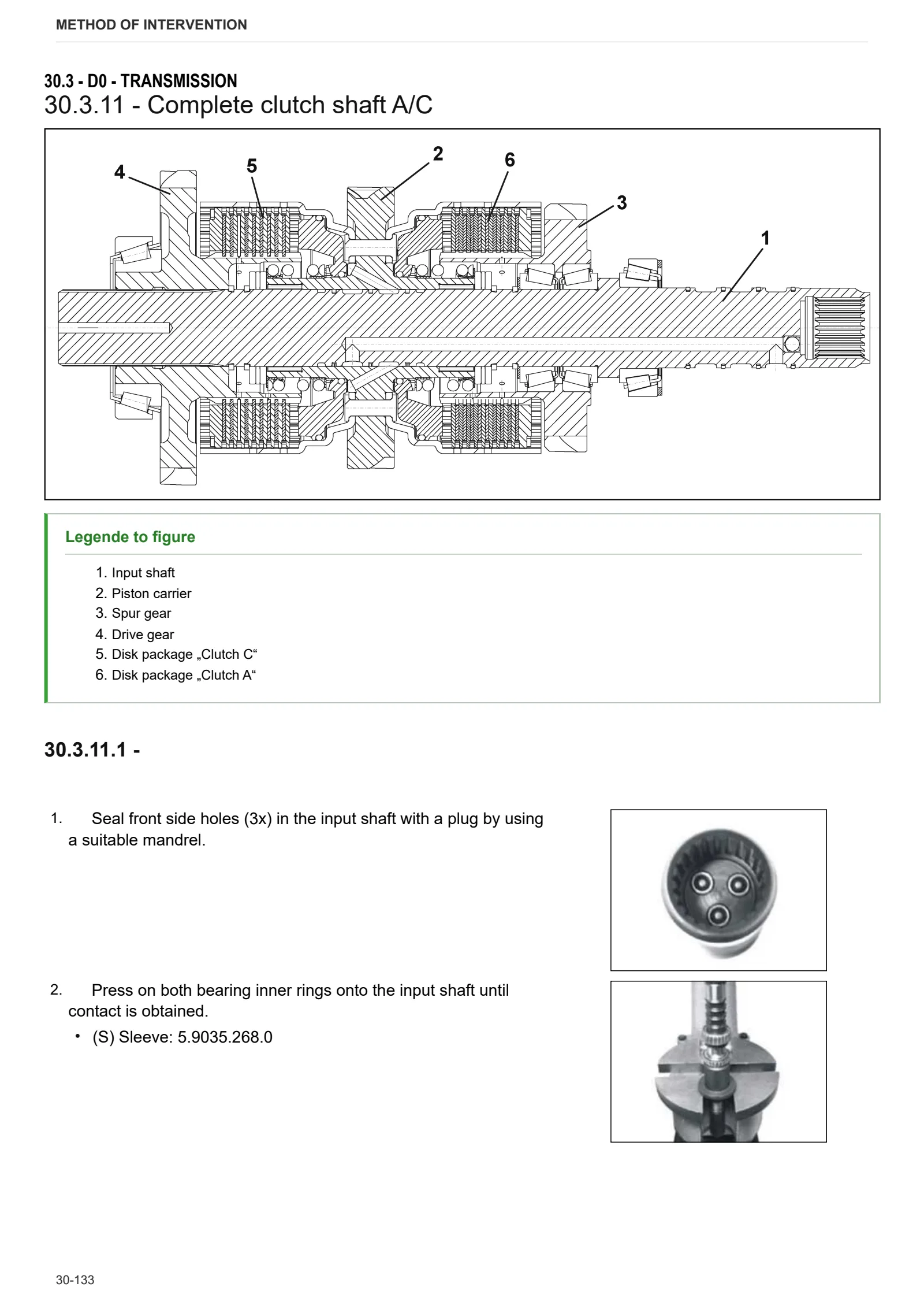
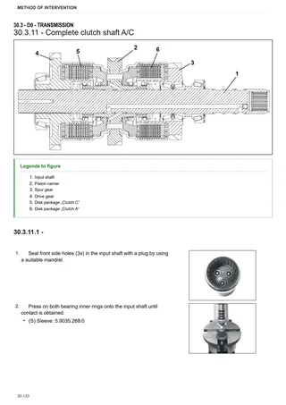
- Complete clutch shaft A/C
- Complete clutch shaft B/D
- Complete clutch shaft F/G
- Disassemble clutch housing
- Preassembly clutch housing
- Disassemble main transmission
- Disassemble front wheel drive
- Preassemble front wheel drive clutch
- Disassemble crawler gear shifting
- Disassemble main clutch
- Preassemble main clutch
- Disassemble shift control (mechanical)
- Disassemble main shaft
- Disassemble countershaft
- Disassemble pump drive gear
- Preassemble transmission housing
- Reassemble pump drive gear
- Preassemble countershaft
- Preassemble main shaft and install it into the transmission housing
- Mount shift control (mechanical part)
- Mount the completed main clutch and crawler
- Reassemble proportional valve (main clutch)
- Mount powershift transmission to the main transmission and adjust crawler shift travel
- Preassemble and mount pump drive
- Disassemble hydraulic shift control
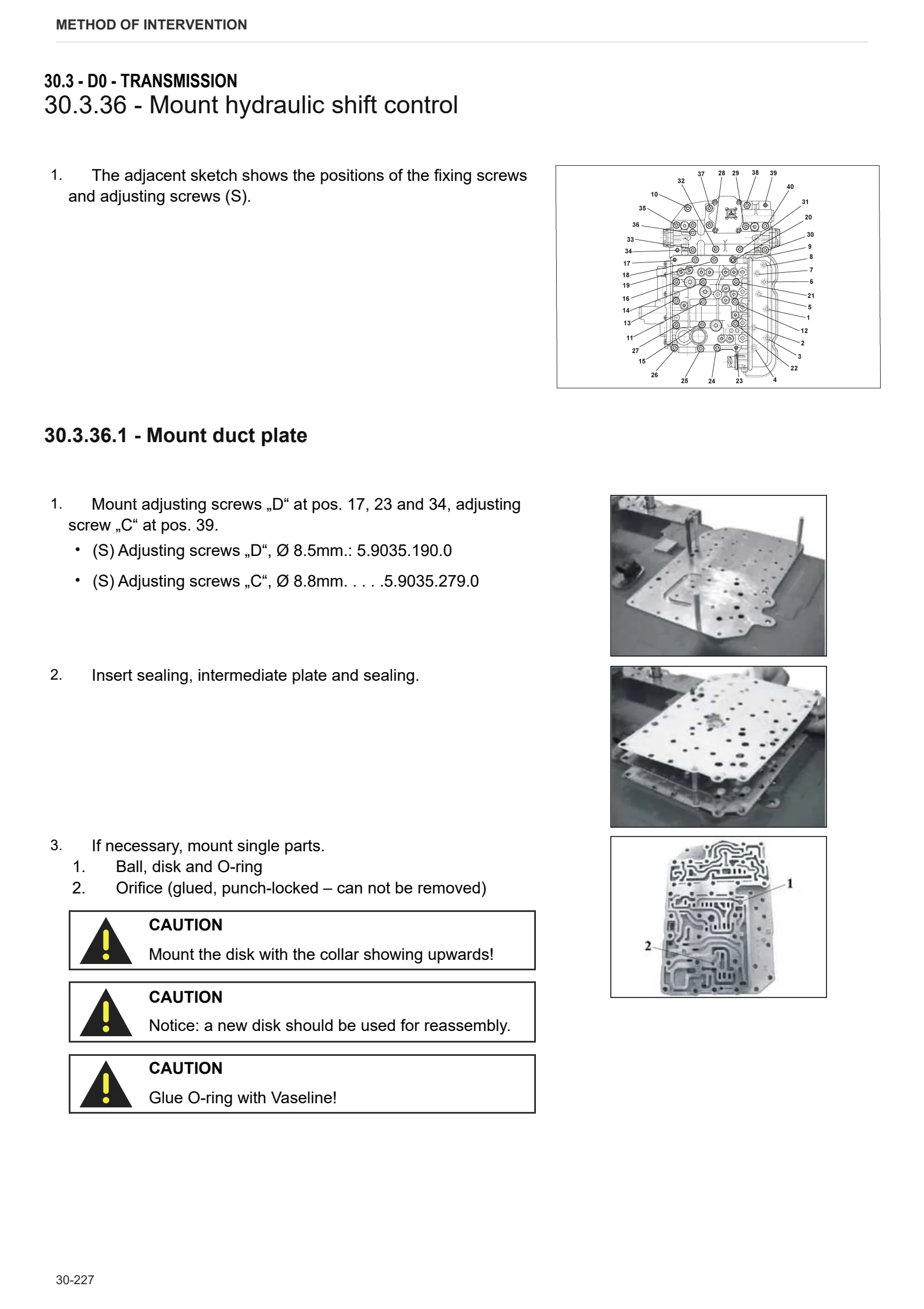
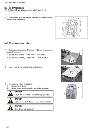
- Mount hydraulic shift control
- Remote control
- Mount the complete rear axle to the transmission housing
- Mount oil supply
F0 – Front axle
- Troubleshooting
- Toe-in/steering angle/assembly tests
- Steering cylinders assembly
- Axle shaft assembly
- Differential assembly – carrier
- Differential disassembly – ML version
- Differential disassembly – LS version
- Checking the bevel gear pair
- Flange assembly
- Bevel pinion assembly
- Planetary reduction gear assembly
- Planetary reduction gear assembly
- Wheel hub assembly
- Brake assembly
L0 – Electrical system
- Steering position sensor assembly
Service Info
A0 – TRACTOR
- Diagnostics 2026 subscription
- After-sales 2026 subscription
- SERVICE NEWS RESEARCH GUIDE
- Diagnostics 2025 subscription
- After-sales 2025 subscription
- Diagnostics 2023 subscription
- Diagnostics 2024 subscription
- Diagnostics 2022 subscription
- Diagnostics 2021 subscription
- After-sales 2024 subscription
- After-sales 2023 subscription
- After-sales 2022 subscription
- After-sales 2021 subscription
- After-sales 2019 subscription
- SDF Parts and SDF Service DVV 04/2014, version 26
- Diagnostics – 2020 subscription
- After-sales – 2020 subscription
- After-sales – 2018 subscription
- Service and Spare Parts – 2017 Subscription
B0 – ENGINE
- Flushing the lubrication circuit
- Deutz AG engine oil specifications
C0 – ENGINE ACCESSORIES
- Diagnostic protocol – AdBlue – Float level unit
- Filter and prefilter tool p/n 5.9035.865.0
F0 – FRONT AXLE
- Check the front axle steering knuckles for wear
- Steering behavior check procedure
G0 – BODYWORK – CAB
- Air conditioning system recharging
H0 – HYDRAULIC AND PNEUMATIC SYSTEM|
- Hydraulic CUNA trailer braking kit (ITALY)
- Single connection hydraulic braking kit availability update – only for EUROPEAN market
- L0 – ELECTRIC AL SYSTEM