Document overview
Workshop Manual for SAME IRON 130 DCR → WSXJ690200LS10001 / 30001 from the IRON (STAGE 3A) family. Digital PDF in English with 1,487 pages.
The corresponding English table of contents contains 44 sections and 364 individual topics.
Main sections included
- Introduction
- Safety
- Technical characteristics
- Calibrations and electronic diagnosis
- Method of intervention
- Wiring diagrams
- Service Info
Document details
- Brand: SAME
- Family: IRON (STAGE 3A)
- Model: IRON 130 DCR
- Starting serial number: WSXJ690200LS10001 / 30001
- Document type: Workshop Manual
- Language: English
- Pages: 1,487
- File size: 146.77 MiB
- Format: Digital PDF download
Compatibility
Before purchasing, verify that your machine model and reference code match SAME IRON 130 DCR → WSXJ690200LS10001 / 30001.
Complete table of contents
Introduction
- Units of measurement and conversion factors
- Tightening torques
Safety
Preface
- Important notes concerning safety
Important safety information
- Recognising hazards
- Indications for persons in contact with the tractor
Safety rules
- Risks during tractor preparation
- Risks during maintenance
- Work on machine systems
- Special disassembly/assembly/inspection procedures
Safety pictograms
- Replacing safety pictograms
Environmental risks
- Hazards associated with the operating environment
Technical characteristics
Engine
- Components of the TCD 2012 L04/L06 2V DCR engine
- Test and adjustment data (L3)
- Tightening requirements TCD 2012 L04/L06 2V DCR engine
Transmission
- Transmission
- Rear PTO
Rear axle
- Rear axle
Front axle
- Front axle
Bodywork – Cab – Platform
- Air conditioning system
Hydraulic system
- Hydraulic system
- Variable displacement pump and boost pump
- Operation of the variable displacement pump
- Steering gear pump and priority valve
- Gear pump ZF 7200
- Load sensing valve, pressure cut-off valve
- Power steering
- Hydraulic front axle suspension
- Front suspension assembly / INTEGRALL
- Remote control valve
- Rear lift control valve
- Braking system
- Hydraulic trailer braking system – Italy version
- Hydraulic trailer braking system – Export version
- Trailer air braking system – Italy version
- Trailer air braking system – Export version
- Trailer air braking valve (2-way)
- Trailer air braking valve (1-way)
- Compressor, Pressure reducing valve, Cab suspension valve
Calibrations and electronic diagnosis
Diagnostic tools
- Position of control units and diagnostic instruments
SDF Analyser
- SDF Analyser
- SDF Analyser – Diagnostic socket connection
Serdia 2000
- SERDIA 2000 level III” software
- Serdia
- SERDIA – Diagnostic socket connection
Diagnostic tool screens
- Electronic system
- ECU interrogation
Commissioning and calibrating the tractor
- Introduction to commissioning the tractor
- Calibration screens for ART/PC Tester
- Renewal of the engine control unit – Introduction
- Renewal of the engine control unit – Reading and saving DATASET
- Renewal of the engine control unit – Programming the control unit with DATASET
- HLHP control unit – Calibration of the accelerator pedal
- HLHP control unit – Calibration of the hand throttle lever
- Renewal of the transmission control unit – Introduction
- Renewal of the transmission control unit – Transmission type configuration
- Renewal of the transmission control unit – Tyres type configuration
- Renewal of the transmission control unit – Configuration of the wheel circumference (using the ART)
- Renewal of the transmission control unit – Configuration of the wheel circumference (without using the ART)
- Renewal of the transmission control unit – Configuration of the maximum travel speed
- Renewal of the transmission control unit – Calibration of the clutch pedal
- Renewal of the transmission control unit – Calibration of the main clutch
- Renewal of the HLHP control unit – Introduction
- Renewal of the HLHP control unit – Initialization of the HLHP control unit
- Renewal of the HLHP control unit – Configuration of the tractor model
- Renewal of the HLHP control unit – Configure the system for presence of front PTO
- Renewal of the HLHP control unit – SBA / ASM system enable
- Renewal of the HLHP control unit – Calibration the steering angle sensor
- Renewal of the HLHP control unit – Configuration for presence of the RADAR
- Renewal of the HLHP control unit – Calibrating low and high positions of the lift
- Renewal of the HLHP control unit – Front axle suspension system enable
- Renewal of the HLHP control unit – Setting the instrument control panel display language
- Renewal of the HLHP control unit – Configuration for presence of the automatic A/C
- Renewal of the HLHP control unit – Configuring the quantity of auxiliary services
- Renewal of the HLHP control unit – Rear control valves identification
- Renewal of the armrest control unit
- Renewal of the Infocenter control unit
- Cancellation of all alarms
- Monitor screens for ART/PC Tester
- Test screens for ART/PC Tester
- Alarm list screens for ART/PC Tester
ECU alarms
- FMI code
Engine alarms
- Engine control unit alarms – ART codes
Transmission alarms
- Transmission alarms
Armrest alarms
- Armrest control unit alarms
HLHP alarms
- HLHP control unit alarms
Method of intervention
- Introduction – Engines
- Tools for engine disassembly and reassembly
- Workshop tools for engine disassembly and reassembly
B0 – Engine
- Air conditioning compressor drive belt
- Tension adjustment of the fan and air conditioning compressor drive belt
- Alternator, fuel pump and water pump drive belt
- Tension adjustment of the alternator, fuel pump and water pump drive belt
- Check the compression value (L3)
- Assembly and disassembly of the engine on the assembly stand (L3)
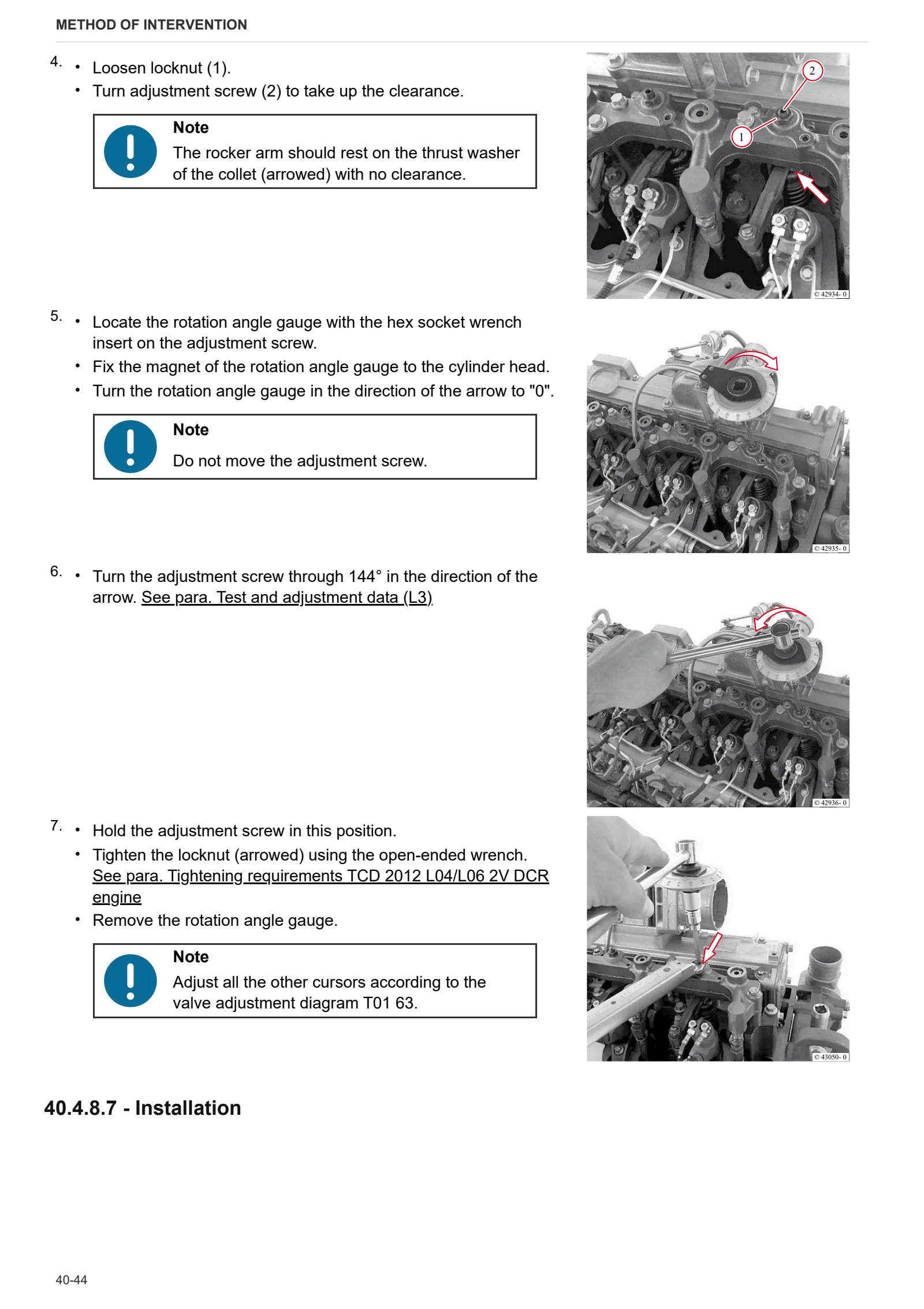
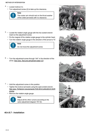
- Valve clearance adjustment (with the exhaust gas recirculation module absent or removed) (L3)
- Valve clearance adjustment (with the exhaust gas recirculation module installed) (L3)
- Disassembly and assembly of the rocker and support (L3)
- Disassemble and complete the rocker and support, check
- Disassembly and assembly of the cylinder head (L3)
- Valve assembly and disassembly (L3)
- Valve check (L3)
- Check the valve guide (L3)
- Check the valve residual (L3)
- Assembly and disassembly of the crankshaft (L3)
- Crankshaft check (L3)
- Replace the crankshaft O-ring (flywheel end) (L3)
- Replace the crankshaft O-ring (opposite end to flywheel) (L3)
- Connecting rod drum check (L3)
- Disassembly and assembly of the piston and connecting rod drum (L3)
- Check the piston (L3)
- Check the piston rings and piston grooves (L3)
- Assembly and disassembly of the piston cooling nozzles (L3)
- Removing and fitting crankcase breather (L3)
- Checking cylinder (L3)
- Removal and refitting of the front cover (opposite end to flywheel) (L3)
- Disassembly and assembly of the connector box (L3)
- Changing the engine oil
- Disassembly and assembly of the gear case cover (L3)
- Assembly and disassembly of the camshaft (L3)
- Check the camshaft (L3)
- Disassembly and assembly of the turbocharger (L3)
- Disassembly and assembly of the turbocharging air duct (L3)
- Fitting and removing the exhaust gas recovery module (L3)
- Removing and fitting the fuel delivery pump (driven by ribbed V-belt) (L3)
- Removing and fitting the fuel control unit (L3)
- Removing and fitting high pressure pump (installation position A) (L3)
- Removing and fitting high pressure pump (installation position B) (L3)
- Removing and fitting the common rail system (L3)
- Removing and fitting injector (L3)
- Removing and fitting the pressure cut-off valve (L3)
- Removing and fitting the fuel pressure transducer (L3)
- Assembly and disassembly of the oil intake pipe (L3)
- Disassembly and assembly of the lubricant oil sump (L3)
- Removing and fitting the lubricant oil cooler housing (L3)
- Removing and fitting the lubricant oil filter (L3)
- Removing and fitting the oil pressure switch (L3)
- Removing and fitting reservoir (L3)
- Removing and fitting the coolant pump (driven by ribbed V-belt) (L3)
- Removing and refitting fan motor (L3)
- Removing and fitting fan motor (L3)
- Removing and fitting fan mount (L3)
- Disassembly and assembly of the torsional vibration damper (L3)
- Removing and fitting belt tensioner (ribbed V-belt) (L3)
- Assembly and disassembly of the flywheel (L3)
C0 – Engine accessories
- Checking that the radiator is clean
- Disassembly and assembly of the oil radiator (L3)
- Fitting and removing thermostat (L3)
- Testing the thermostat (after removal)
- Removal and refitting of the crankshaft speed sensor (L3)
- Removal and refitting of the camshaft speed sensor (L3)
- Removing and refitting the exhaust manifold (L3)
- Fitting and removing the solenoid valve (exhaust gas recovery module) (L3)
- Removing and fitting the fuel filter mount (L3)
- Fitting and removing the rail pressure sensor (L3)
- Assembly and disassembly of the temperature sender (L3)
- Removal and refitting of the supply air pressure/temperature sender (L3)
- Removing and fitting the alternator (driven by ribbed V-belt) (L3)
- Disassembly and assembly of the starter (L3)
- Disassembly and assembly of the cable bundle (L3)
- Fitting and removing the glow plugs (L3)
D0 – Transmission
- Separate transmission components
- Remove bearing cover
- Disassembl e clutch A/C
- Disassembly clutch B/D
- Disassemble clutch F/G
- Complete clutch shaft A/C
- Complete clutch shaft B/D
- Complete clutch shaft F/G
- Disassemble clutch housing
- Preassembly clutch housing
- Disassemble main transmission
- Disassemble front wheel drive
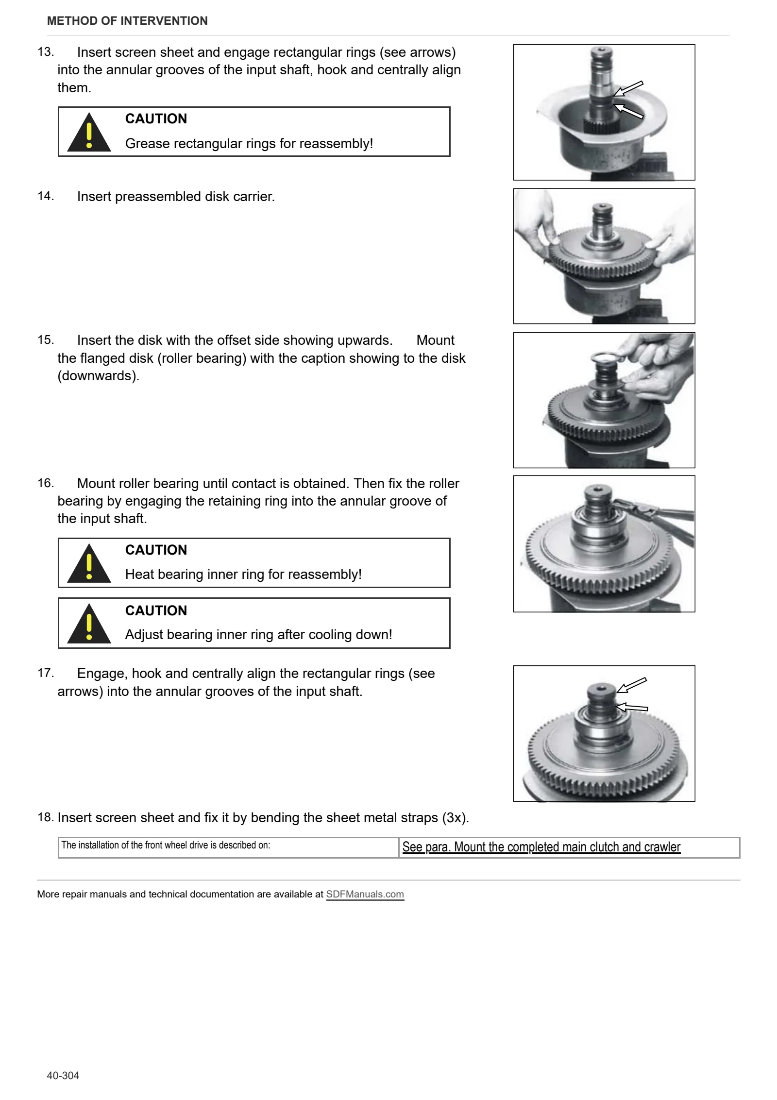
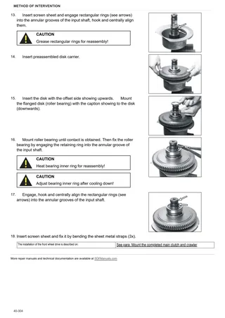
- Preassemble front wheel drive clutch
- Disassemble crawler gear shifting
- Disassemble main clutch
- Preassemble main clutch
- Disassemble shift control (mechanical)
- Disassemble main shaft
- Disassemble countershaft
- Disassemble pump drive gear
- Preassemble transmission housing
- Reassemble pump drive gear
- Preassemble countershaft
- Preassemble main shaft and install it into the transmission housing
- Mount shift control (mechanical part)
- Mount the completed main clutch and crawler
- Reassemble proportional valve (main clutch)
- Mount powershift transmission to the main transmission and adjust crawler shift travel
- Preassemble and mount pump drive
- Disassemble hydraulic shift control
- Mount hydraulic shift control
- Remote control
- Mount the complete rear axle to the transmission housing
- Mount oil supply
E0 – Rear axle
- Rear axle
- Disassembling the axle funnel
- Dismantling the brake
- Dismantling the differential
- Removing PTO gear
- Dismantling the oil supply
- Dismantling the linkage
- Pre-assembling the rear axle housing
- Assembling the linkage
- Assembling the oil supply
- Assembling the control unit
- Assembling the valve block
- PTO gear assembly
- Assembling the PTO shaft coupling
- Assembling PTO shaft shift unit
- Assembling the differential
- Assembling the brake
- Setting the rear wheel brake
- Fitting the axle housing
- Attaching complete rear axle to the transmission casing
F0 – Front axle
- Troubleshooting
- Toe-in/steering angle/assembly tests
- Steering cylinders assembly
- Axle shaft assembly
- Differential assembly – carrier
- Differential disassembly – ML version
- Differential disassembly – LS version
- Checking the bevel gear pair
- Flange assembly
- Bevel pinion assembly
- Planetary reduction gear assembly
- Planetary reduction gear assembly
- Wheel hub assembly
- Brake assembly
V1 – AFTERMARKET KITS
- Installation of the air conditioning kit
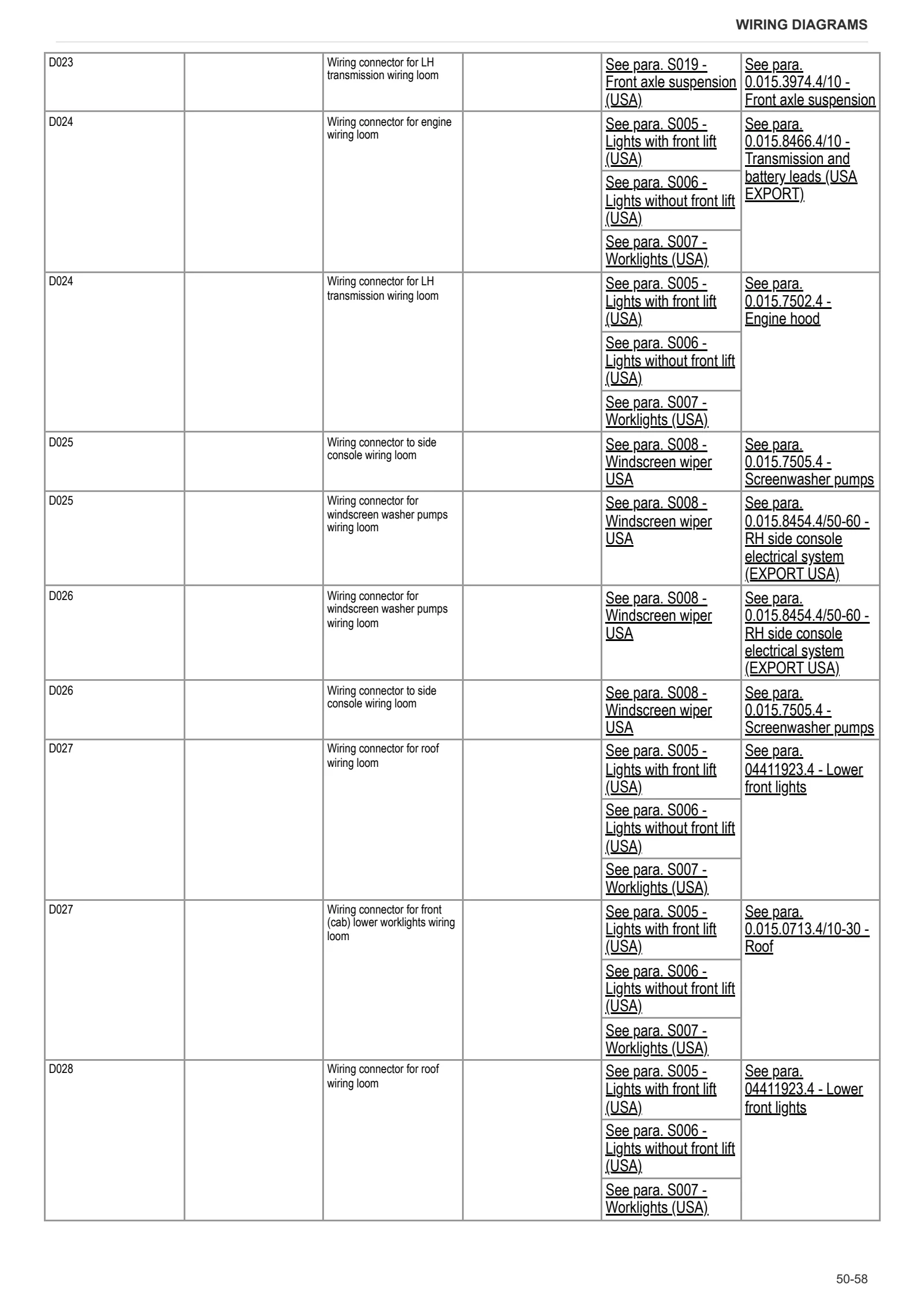
Wiring diagrams
Components
- A – Starting and charging
- B – Fuses
- C – Earths
- D – Intermediate connections
- E – On-board instruments and visual and audible indicators
- F – External lights (rotating beacon)
- G – Interior lights
- H – Manual electrical controls (steering column switch)
- I – Circuit breakers
- J – Relays
- K – Sensors and transmitters
- L – Electromagnets and solenoid valves
- M – Electrical/electronic devices, Flasher units and Timers
- N – Electric motors and actuators
- O – Resistors and rheostats
- P – Various services
- R – Diagnostics
Systems
- S001 – Electronic engine governor ITA
- S001 – Electronic engine governor USA
- S002 – Preheating ITA
- S002 – Preheating USA
- S003 – Starting ITA
- S003 – Starting USA
- S004 – Diagnostics ITA
- S004 – Diagnostics USA
- S005 – Lights with front lift (ITA)
- S005 – Lights with front lift (USA)
- S006 – Lights without front lift (ITA)
- S006 – Lights without front lift (USA)
- S007 – Worklights (ITA)
- S007 – Worklights (USA)
- S009 – Windscreen wiper ITA
- S008 – Windscreen wiper USA
- S009 – Instrument panel ITA
- S009 – Instrument panel USA
- S010 – Radio ITA
- S010 – Radio USA
- S011 – Air conditioner ITA
- S011 – Air conditioner USA
- S011 – Transmission (ITA)
- S011 – Transmission (USA)
- S013 – PTO ITA
- S013 – PTO USA
- S014 – Accessories (ITA)
- S014 – Accessories (USA)
- S015 – Can Bus (ITA)
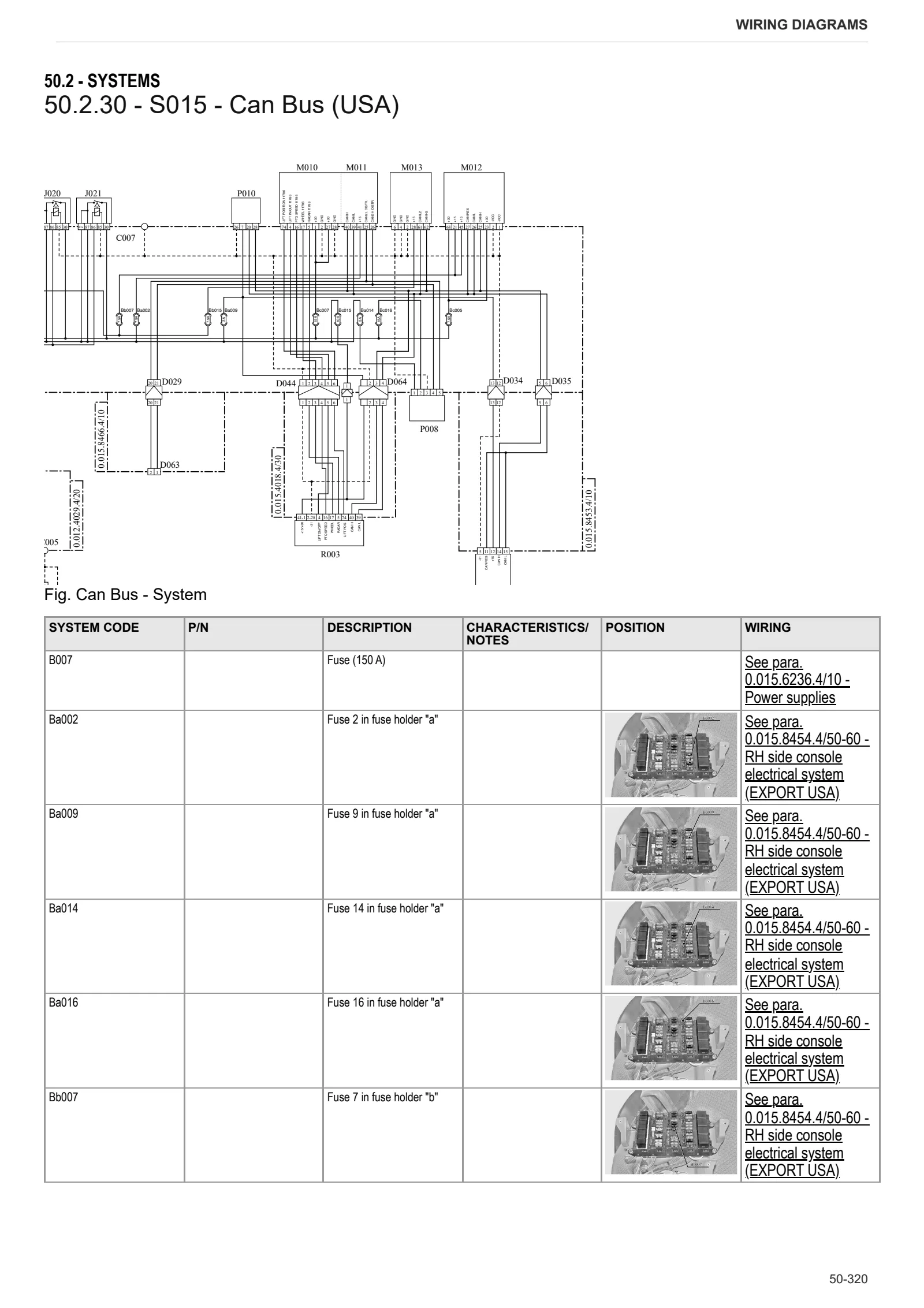
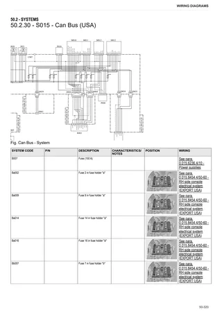
- S015 – Can Bus (USA)
- S016 – Brakes (ITA)
- S016 – Brakes (USA)
- S017 – Trailer brakes – hydraulic braking (ITA)
- S018 – Trailer brakes – air braking (ITA)
- S018 – Trailer brakes – air braking (USA)
- S019 – Front axle suspension (ITA)
- S019 – Front axle suspension (USA)
- S020 – Rear lift (ITA)
- S020 – Rear lift (USA)
Wiring harnesses
- 0.012.2018.4/20 – Number plate light
- 0.012.4029.4/20 – Battery negative
- 0.013.4085.4/20 – Headlights wiring loom
- 0.014.0007.4/10 – Lights selector switch
- 0.014.4810.4 – Front loader
- 0.014.9570.4/10 – ISO socket system
- 0.015.0712.4/10 – Front console
- 0.015.0713.4/10-30 – Roof
- 0.015.3692.4/10 – Fender
- 0.015.3693.4/10 – Rear cable for sidelights/turn indicators and PTO/lift switch
- 0.015.3974.4/10 – Front axle suspension
- 0.015.4018.4/30 – LH transmission
- 0.015.4019.4/30 – RH transmission
- 0.015.4257.4/10 – PTO sensor wiring loom (USA EXPORT)
- 0.015.5452.4 – Comfort package
- 0.015.6236.4/10 – Power supplies
- 0.015.7461.4/20 – Braking and front lift interface
- 0.015.7502.4 – Engine hood
- 0.015.7505.4 – Screenwasher pumps
- 0.015.8453.4/10 – Instrument panel and flasher units (USA EXPORT)
- 0.015.8454.4/50-60 – RH side console electrical system (EXPORT USA)
- 0.015.8456.4 – Tail lights with fender extensions – (EXPORT USA)
- 0.015.8466.4/10 – Transmission and battery leads (USA EXPORT)
- 0.016.0642.4/20 – Rear lower worklights XENON version
- 0.016.0650.4/10 – Supplementary worklights on arm (XENON)
- 0.017.5493.4 – Worklights control relay
- 0.017.1768.4/10 – Tail lights without fender extensions – (EXPORT USA)
- 0.017.1769.4/10 – Tail lights with fender extensions – (EXPORT USA)
- 0.017.3486.4 – Air conditioning system condenser pressure switch
- 0.900.0783.8 – Air conditioning
- 0.900.0816.0 – Front PTO
- 0443.7356.4/10 – Hydraulic braking ITALY
- 04411923.4 – Lower front lights
- 0421.5528 – Engine wiring loom
- 0442.2156-20 Battery positive
- 0442.8092.4 Sidelights and front turn indicators
- 0443.7355.4-10 – Air braking
- 0441.2045 – Wiper motor
- 0.015.0740.4/-90 – Side console
Service Info
A0 – TRACTOR
- Diagnostics 2026 subscription
- After-sales 2026 subscription
- SERVICE NEWS RESEARCH GUIDE
- Diagnostics 2025 subscription
- After-sales 2025 subscription
- Diagnostics 2023 subscription
- Diagnostics 2024 subscription
- Diagnostics 2022 subscription
- Diagnostics 2021 subscription
- Technical Documentation DVD 06/2009
- Technical Documentation DVD 07/2008
- SDF LUBRICANTS: Lubricant oils and coolant fluids
- After-sales 2024 subscription
- After-sales 2023 subscription
- After-sales 2022 subscription
- After-sales 2021 subscription
- After-sales 2019 subscription
- SDF Parts and SDF Service DVV 04/2014, version 26
- Technical Documentation DVD 03/2010
- New function: Download PDF manuals
- Diagnostics – 2020 subscription
- After-sales – 2020 subscription
- After-sales – 2018 subscription
- Service and Spare Parts – 2017 Subscription
- SDF Parts and SDF Service DVDs 05/2014 version 25
- SDF Parts and SDF Service DVDs 03/2013 version 24
B0 – ENGINE
- Engine fan mount failure
- Flushing the lubrication circuit
- Deutz AG engine oil specifications
- SerDia 2010 updating license file
C0 – ENGINE ACCESSORIES
- Diagnostic protocol – AdBlue – Float level unit
- Filter and prefilter tool p/n 5.9035.865.0
- Additive for diesel fuel
F0 – FRONT AXLE
- Carraro front axle model 20.26 Final reduction
- Check the front axle steering knuckles for wear
- Steering behavior check procedure
G0 – BODYWORK – CAB
- Air conditioning system filter-drier
- Air conditioning system recharging
H0 – HYDRAULIC AND PNEUMATIC SYSTEM|
- Hydraulic CUNA trailer braking kit (ITALY)
- Single connection hydraulic braking kit availability update – only for EUROPEAN market
- L0 – ELECTRIC AL SYSTEM