

Document overview
Workshop Manual PDF for DEUTZ FAHR 6135 C RVSHIFT → ZKDLS90200TD10001, Series 6 C RVSHIFT (STAGE 2) family. Document language: English; 1,266 pages.
The corresponding English table of contents contains 41 sections and 553 individual topics.
Main sections included
- Introduction
- Safety
- Technical characteristics
- Calibrations and electronic diagnosis
- Method of intervention
- Wiring diagrams
- Service Info
Document details
- Brand: DEUTZ FAHR
- Family: Series 6 C RVSHIFT (STAGE 2)
- Model: 6135 C RVSHIFT
- Starting serial number: ZKDLS90200TD10001
- Document type: Workshop Manual
- Language: English
- Pages: 1,266
- File size: 386.80 MiB
- Format: Digital PDF download
Compatibility
Before purchasing, verify that your machine model and reference code match DEUTZ FAHR 6135 C RVSHIFT → ZKDLS90200TD10001.
Complete table of contents
Introduction
- Tightening torques
- Pump tightening torques
- Wheel nut/screw tightening torques
- Tightening torques for nuts and bolts of electrical connections
- Installation of solenoid valves and cartridge valves
- Installation of quick couplers
- Units of measurement and conversion factors
Safety
Preface
- Important notes concerning safety
Important safety information
- Recognising hazards
- Indications for persons in contact with the tractor
Safety rules
- Risks during tractor preparation
- Risks during maintenance
- Work on machine systems
- Special disassembly/assembly/inspection procedures
Safety pictograms
- Replacing safety pictograms
Environmental risks
- Hazards associated with the operating environment
Technical characteristics
Engine
- Introduction – Engines
- Cold start system (preheat glow plugs)
- Engine cooling system
- Engine intake system
- Engine injection system – low pressure circuit
- Exhaust backpressure, engine oil temperature
- Fuel injection system – Common Rail System
- Engine air intake system
- Turbocharging system
- Exhaust gas recirculation system (EGR)
- Exhaust aftertreatment system
- Technical data and exhaust gas after-treatment systems – KF stage 5 engine
- Technical data, rockers – tappets
- Technical data and dimensions: valves – valve springs
- Technical data and dimensions: heads – valve guides – valve seats
- Technical data: counter-rotating masses
- Technical data: timing system gears
- Camshaft technical data
- Technical data: Connecting rods
- Technical data: pistons – piston rings
- Technical data: crankshaft
- Technical data: cylinder block
Engine accessories
- Complete cooling pack
- Complete cooling pack
- Coolant radiator
- Expansion tank
- Expansion tank
- Intercooler
- Intercooler
- Air filter
- Diesel fuel tank
- Diesel radiator
- Diesel radiator
- Starter motor
- DOC catalytic converter and DPF diesel particulate filter
- DOC catalytic converter
- AdBlue® technical characteristics
- AdBlue pump
- AdBlue injector
- AdBlue valve
- AdBlue tank
- AdBlue float
- Exhaust pipe
- Exhaust pipe
- Air compressor
- Air compressor
Transmission
- Continuously variable transmission
- Mechanical variable ratio transmission
- Cross section of transmission
- “Input” clutch
- Variable ratio transmission unit
- Shuttle unit
- Range change
- Pump carrier
Rear axle
- Rear wheel carrier
- Park brake unit
- Rear differential
Front axle
- Front axle 4 WD
- Disc type front differential lock (ASM)
- Planetary reduction gearbox
Bodywork – Cab – Platform
- External views of the tractor
- External views of the tractor
- Main technical data
- Viste interni cabina
- Front console and cab pillars
- Instrument panel
- Left hand console
- Right hand console, “configuration version 1”
- Right hand console, “configuration version 2”
- Roof panel
- Air conditioning system
- Air conditioning system – Charging
- Air conditioning compressor
- Air conditioning condenser
Hydraulic system
- Auxiliary hydraulic circuit, optional version
- Optional hydraulic circuit
- Transmission hydraulic circuit, base version
- Hydraulic circuit
- Auxiliary hydraulic circuit, optional version
- Base hydraulic system, gear pump
- Full house hydraulic circuit
- Base hydraulic circuit with LS pump
- Optional hydraulic circuit
- Optional hydraulic circuit
- Optional hydraulic circuit
- Transmission hydraulic circuit, base version
- Transmission hydraulic circuit, full house version
- Transmission hydraulic circuit, base version
- Transmission hydraulic circuit, optional version
- Location of hydraulic system components
- Location of hydraulic accumulators
- 45 cc variable displacement pump
- Fixed gear pump (32 cc)
- Fixed gear pump (16 cc)
- Fixed gear pump (11 cc)
- Oil delivery line filter
- Transmission oil radiator
- Bypass thermostat valve
- Braking system
- Park Brake system
- Park Brake valve
- Power steering 80 -160cc
- APS 115-240cc hydraulic steering pump
- 70-170 cc LSRM hydraulic steering unit
- Mechanical spools valve
- Front axle suspension
- Electrohydraulic gear control unit
Calibrations and electronic diagnosis
Commissioning and calibrating the tractor
- Commissioning procedure (EOL)
- Reset ECU (MVCU + GTECU + SVCU)
- Distributor configuration
- Maximum vehicle speed
- Tyre type
- Language
- Units of measurement
- Rapid steer system (SDD)
- Front power take-off (PTO)
- PTOSyncro
- Automatic A/C system
- Engine brake (HEB)
- eVISCO
- Agrosky
- 4WD
- ISO 11786
- Pneumatic trailer brake
- Hydraulic trailer braking
- Iso 11783
- iMonitor
- Stoll
- ASM (Automatic Steering Management)
- Mechanical diverter
- Setting the distributors to neutral position
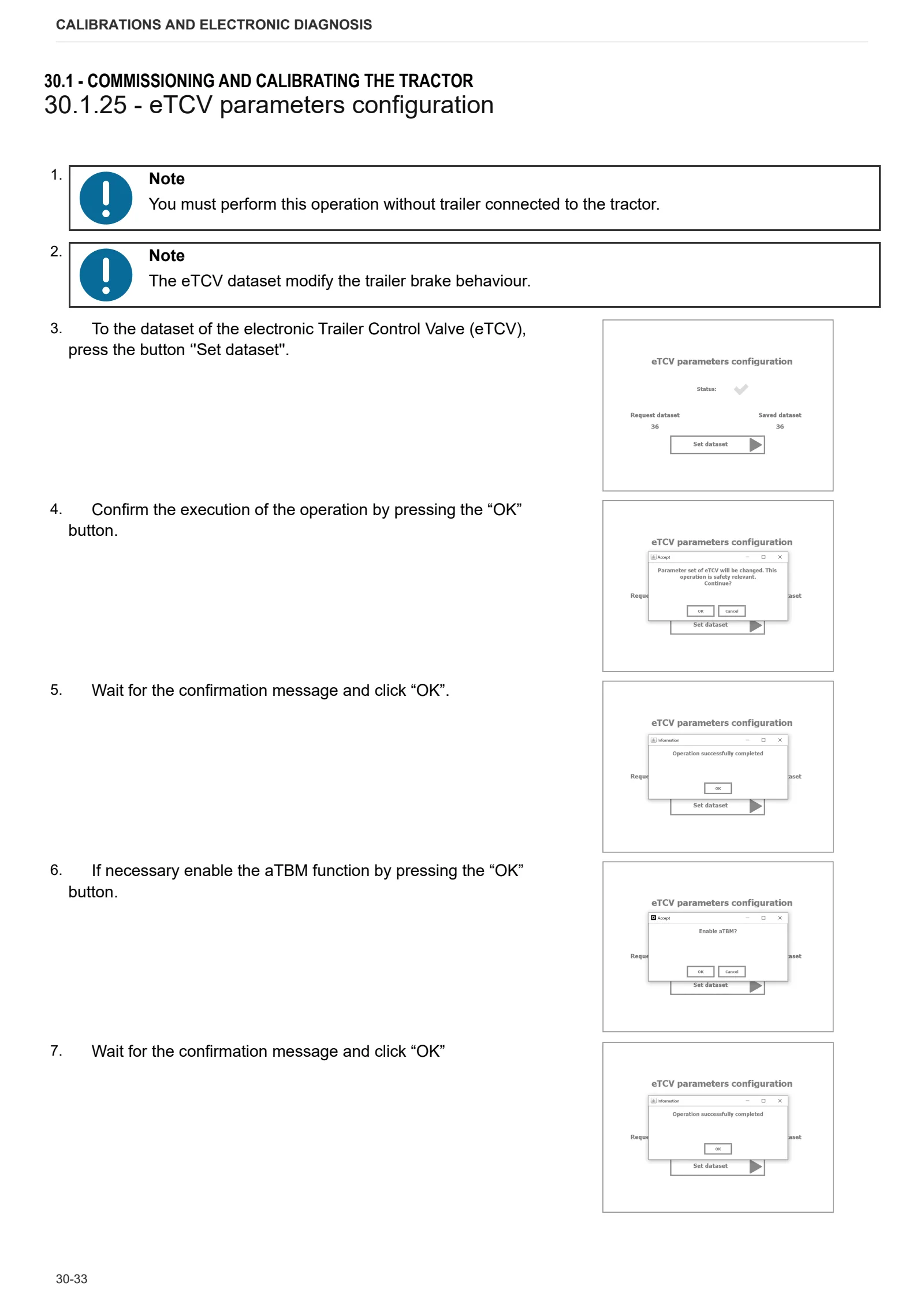
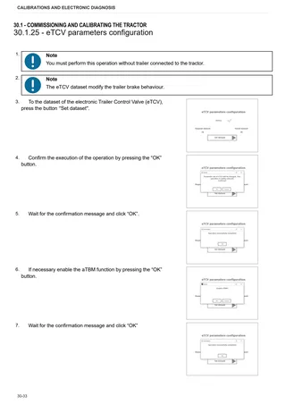
- eTCV parameters configuration
- Hand brake position calibration
- Rear hitch position calibration
- Steering angle calibration
- Front suspension calibration
- IMU calibration
- PTO calibration
- Work reverse clutch calibration
- Hydrostatic unit calibration
ECU alarms
- SDF Severity of alarms
- ECU ALARMS
Software management
- ECUs firmware update
Method of intervention
B0 – Engine
- Complete engine
- Separating engine from transmission
- Engine flywheel
- Tightening procedure for engine components
- Overhauling counter-rotating masses
- Adjusting oil pump gear backlash
- Aligning water pump and crankshaft pulleys
- Power take off gear backlash adjustment
- Test of the thermostat valve
- Engine block-gearbox connector flange
- Cooling jets
- Engine flywheel
- Belt tensioner mounting plate.
- Automatic belt tensioner
- Ancillary utility belt
- Crankshaft pulley and tone wheel
- Crankshaft pulley complete with tone wheel
- Counter-rotating masses
- Crankshaft
- Disassembling pistons and connecting rods
- Cylinder sleeves
- Power take off drive
- Front timing cover
- Rear flange
- Cylinder head covers
- Pushrods
- Cylinder heads
- Intermediate gear and timing
- Disassembling the cylinder heads
- Engine oil and filter
- Turbocharger oil pipes
- Blow-by filter
- Blow-by oil vapour pipe
- Oil sump
- Oil pump
- Oil vapour pipe
- Electro-injectors and common rail
- Thermostat valves
- Coolant manifold
- Oil heat exchanger
- Engine coolant pump
- EGR exhaust gas recirculation pipe
- EGR exhaust gas cooling pipe
- EGR manifold
- Disassembly of the EGR manifold
- Exhaust gas pressure line
- Exhaust manifold
- Intake manifold
- Turbocharger
- Turbocharger exhaust outlet flange
- Mass air flow sensor
- EGR valve
- AdBlue injector
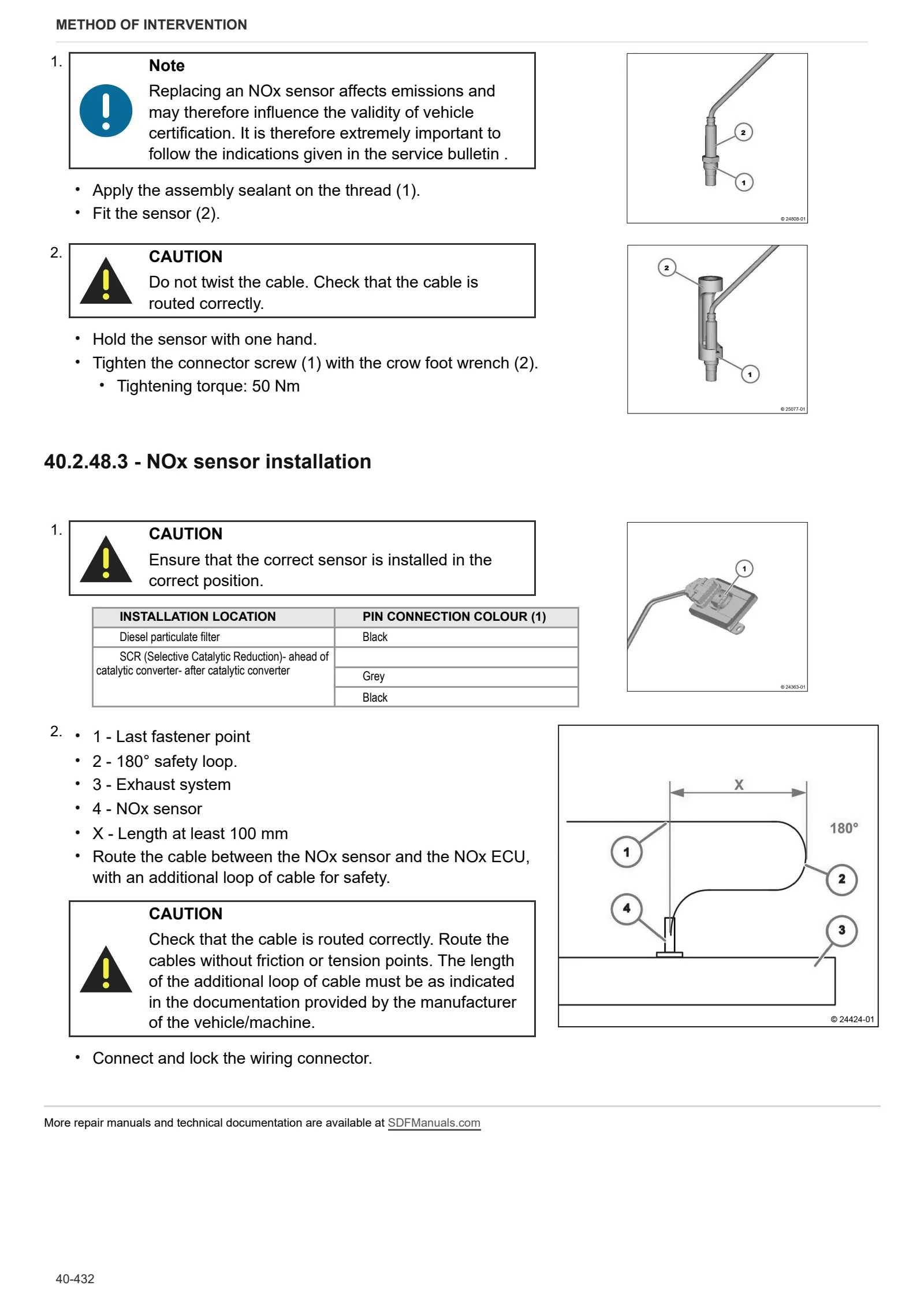
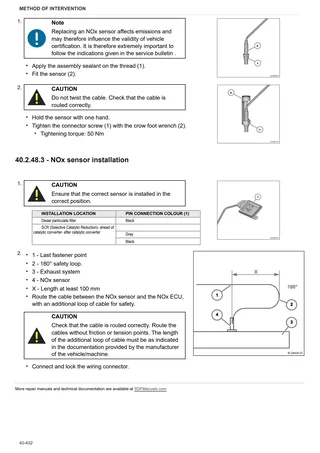
- NOx sensor
- DOC outlet side exhaust temperature sensor
- DOC inlet side exhaust temperature sensor
- Exhaust gas pressure sensor
- Throttle valve actuator
- Alternator
- Boost pressure sensor and air temperature sensor
- Mass air flow sensor
- Crankshaft speed sensor
- Camshaft timing sensor
- Engine oil pressure switch
- Coolant temperature sensor
- Engine oil temperature sensor
- Fuel pressure sensor
- Water in fuel sensor
- Blanking cover (PTO-B)
- Fitting and removing rotation/lock tool
- Assembly and disassembly of the camshaft
- Check the camshaft
- Disassembly and assembly of the control elements
- Measure the pressure in the crankcase
- Blanking tool (crankcase)
- Blanking tool (crankcase)
- Blanking tool (crankcase)
- Breather line
- Breather line
- Valve needle (crankcase breather)
- Replacing the crankshaft seal ring (flywheel side).
- Removing and refitting the housing gasket
- Removing and fitting the V belt pulley/poly-V belt pulley
- Disassembling and assembling the sensor wheel
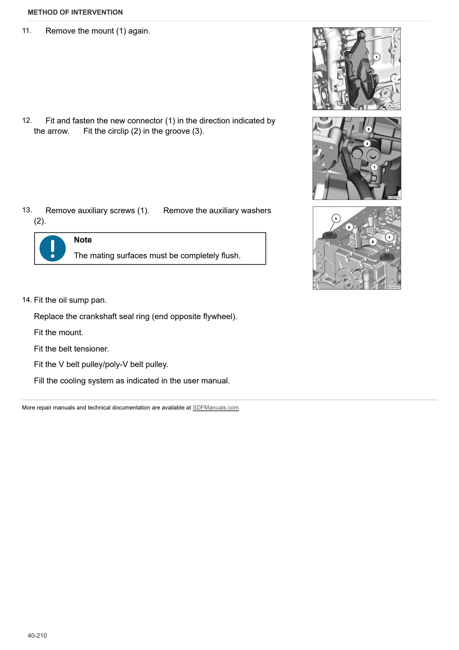
- Replacing crankshaft seal ring (side opposite flywheel)
- Removing and fitting belt tensioner (ribbed V belt)
- Removing and refitting the poly-V-belt
- Removing and refitting the idler roller (poly-V-belt)
- Replacing the ribbed V-belt
- Replacing the belt tensioner
- Checking poly-V-belt and belt tensioner roller
- Pulley (V belt, poly-V belt)
- Mount (belt guard)
- Removing and refitting the camshaft bearing (camshaft removed from engine)
- Fitting and removing the regulator valve
- Removing and refitting crankshaft bearing cap
- Removing and fitting the counterweight drive shaft
- Removing and fitting the crankshaft bearing
- Removing and fitting the crankshaft bearing
- Compression test (with injectors removed from engine)
- Checking compression value (with glow plugs / screw plugs removed)
- Check the crankshaft bearings
- Checking the cylinder
- Fitting and removing the piston cooling nozzle
- Disassembly and reassembly of connecting rod shank
- Check the connecting rod shank
- Disassembling and assembling the piston
- Disassembling and assembling the piston rings
- Check the piston rings
- Check the piston rings
- Measuring piston protrusion
- Disassembling and assembling the gear casing (fastener elements)
- Intermediate gear
- Removing and refitting cylinder head cover
- Turbocharger shield plate
- Disassembling and assembling the cylinder head (fasteners)
- Assembly and disassembly of the valves
- Checking valves, valve guides, valve springs and valve recess
- Checking the lubricant oil level
- Lubricant oil measuring device
- Oil filler neck (crankcase, intake side)
- Removing and fitting lubricant oil sump (heavy version)
- Replacing the lubricating oil filter
- Changing lubricant oil (cast iron lubricant oil sump)
- Removing and fitting the lubricant oil radiator
- Replacing the lubricating oil filter
- Fitting the lubricant oil filter (vrankcase)
- Disassembling and assembling the oil suction pipe
- Removing and fitting the lubricant oil pipe
- Removing and fitting the lubricant oil return pipe (lower section) (Turbocharger)
- Removing and refitting the lubricant oil return pipe – (upper section) – (turbocharger)
- Mount (lubricant oil return line)
- Oil pressure regulator valve (shutter valve)
- Removing and fitting the lubricant oil pump
- Fitting and removing the high pressure pump
- Removing and fitting the injector
- Fuel prefilter
- Fuel filter
- Fitting the fuel pressure transducer
- Level sensor (fuel pre-filter)
- Fuel delivery pump (electric)
- Removing and fitting the rail
- Fitting and removing the pressure limiting valve (Rail)
- Fitting and removing the rail pressure sensor
- Removing and fitting fuel line (injector, rail, high pressure pump)
- Fuel pipe (quick connector)
- Checking injector return flow rate (continuous flow process)
- Checking fuel pressure (low pressure) (fuel delivery and return)
- Checking pressure cut-off valve for internal leaks
- High pressure pump, mating with gear (with gear case disassembled)
- High pressure pump (Solenoid valve, overflow valve)
- Checking the coolant level
- Checking coolant concentration
- Removing and fitting the coolant pump
- Disassembling and assembling the thermostat housing (fastener elements)
- Removing and fitting the thermostat (with thermostat housing removed)
- Checking the thermostat (removed from engine)
- Coolant pipe (cooler – coolant pump)
- Flexible hose (thermostat housing – crankcase)
- Charge air manifold, throttle valve
- Charge air manifold, throttle valve
- Disassembling and assembling the exhaust manifold
- Disassembling and assembling the butterfly valve
- Disassembling and assembling the radiator
- Removing and fitting the exhaust gas recirculation valve
- Removing and fitting the exhaust gas recirculation system pipe
- Removing and fitting diesel particular filter (module size 5.66”)
- Removing and fitting the pressure transducer (exhaust gas recirculation system)
- Blanking screw (cooler – thermostat housing coolant pipe)
- Shield plate (exhaust pipe)
- Pipe (radiator – thermostat housing, exhaust gas recirculation system)
- Exhaust manifold (exhaust gas recirculation)
- Console (exhaust gas recirculation)
- Venturi pipe
- Exhaust manifold (turbocharger)
- Disassembling and assembling charge air pipe
- Removal and refitting of the supply air pressure/temperature sender
- Disassembling and assembling the turbocharger
- Disassembling and assembling the turbocharger
- Removing and fitting the alternator
- Starter
C0 – Engine accessories
- Replacing the coolant
- Water radiator
- Expansion tank
- Fan
- Air filter
- Intercooler
- Oil radiator
- Diesel radiator
- Manual fuel pump
- Diesel fuel tank
- Fuel and filter and prefilter
- DOC exhaust silencer
- Drain pipe
- Intermediate manifold
- AdBlue tank
- AdBlue pump
- Air conditioning compressor
- Alternator mount
- Transverse plate
- Mounting brackets
- Fuel pump
- Fuel prefilter
- Fuel filter
- Filter mounting plate
- High pressure fuel pump
- Glow plug
- Preheat relay
- Starter motor
- Exhaust pipe
- DOC outlet side exhaust flange
- DOC inlet side exhaust flange
- DOC exhaust silencer
- Air compressor
- Replace the fuel filter
- Replacing the fuel filter
- Emptying the water collector bowl
- Bleeding the fuel system (fuel system with mechanical fuel delivery pump)
- Emptying the water collector bowl
- Wiring harness (fasteners, connector)
- Assembling the SCR (Selective Catalytic Reduction) metering unit
- Flushing the SCR (Selective Catalytic Reduction) delivery pump
- Flushing the SCR (Selective Catalytic Reduction) pipe (delivery pump – metering unit)
- Changing the coolant
- Temperature sender (coolant)
- Replace the SCR system delivery pump filter cartridge
- SCR delivery pump (Selective Catalytic Reduction)
- Removing and fitting the glow plugs
- Disassembling and assembling the NOx sensor
- Flushing/Checking SCR (Selective Catalytic Reduction) metering unit
- Blanking elements (exhaust gas after-treatment system)
- Fastener elements (wiring bundle)
- Mount fasteners (starter motor relay)
- Protective cap (connector guides – glow plugs)
- Relay, mount (glow plugs)
- Relay, mount (glow plugs)
- Relay, mount (thermo-starter)
- Level switch (coolant)
- Connector cable (relay – thermo-starter)
- Check the seal of the cooling system
- Camshaft speed sensor
- Crankshaft speed sensor
- Fitting the pressure transducer (lubricant oil pressure)
- Connector coupling
- Connector coupling
- Differential pressure sender (diesel particulate filter)
- Differential pressure sender (diesel particulate filter)
- Temperature sender (inlet air and ambient air temperature)
D0 – Transmission
- Draining and filling the transmission oil
- Applying sealant
- Front gearbox from its rear part
- Separating the gearbox housing from the rear gearbox housing
- Centre gearbox housing (CVT unit)
- Connector housing
- Torsionally flexible coupling and engine flywheel
- INPUT clutch disc replacement
- INPUT unit
- INPUT unit disassembly
- Front gearbox casing cover
- Hydrostatic unit
- Hydrostatic unit pipes
- Front section of dual traction shaft (in clutch housing)
- Disassembling the front section of the dual traction shaft
- Rear section of 4WD shaft (in clutch housing) and tone sleeve
- Removing the tone sleeve
- Replacing the variator input shaft bearings
- Replacing the WORK and TRANSPORT clutch assemblies (with the intermediate casing installed)
- Variator unit input gear assembly
- Disassembling the variator input gear unit
- WORK and TRANSPORT clutch-planetary reduction gearbox assembly
- Planetary reduction gearbox for the WORK and TRANSPORT clutches
- Disassembling the WORK and TRANSPORT planetary reduction gearbox
- Disassembling the WORK and TRANSPORT clutches
- REVERSE clutch-planetary reduction unit
- Disassembling the REVERSE planetary reduction unit
- Hydraulic pump drive
- Disassembling the hydraulic pump drive unit
- Speed range gear shafts
- Electrohydraulic range gearbox
- Disassembling the electrohydraulic range gearbox
- Electrohydraulic range gearbox position sensor and relative mount
- Disassembling the electrohydraulic range gearbox position sensor mount
- Disassembling the idler gear
- PTO engagement clutch
- Disassembling PTO engagement clutch
- PTO casing
- Disassembling the PTO casing
- PTO drive shaft
- PTO speed selection lever
- PTO driven shaft
- Disassembling the PTO driven shaft
- Removing the groundspeed PTO cover
- Differential pinion
- Disassembling the differential pinion
- Disassembling the HD (Heavy Duty) range gear
- Dual traction output shaft
- Disassembling the dual traction output shaft
- Dual traction output shaft transfer idler gear
- Dual traction clutch
- Disassembling the dual traction clutch
- Centre section of dual traction shaft (in variable transmission unit)
- Disassembling the centre section of the dual traction shaft
E0 – Rear axle
- Bleeding the braking system
- Rear axle
- Removing right/left hand rear axle
- Brake flange
- Park Brake assembly
- Park Brake unit disassembly
- Rear differential
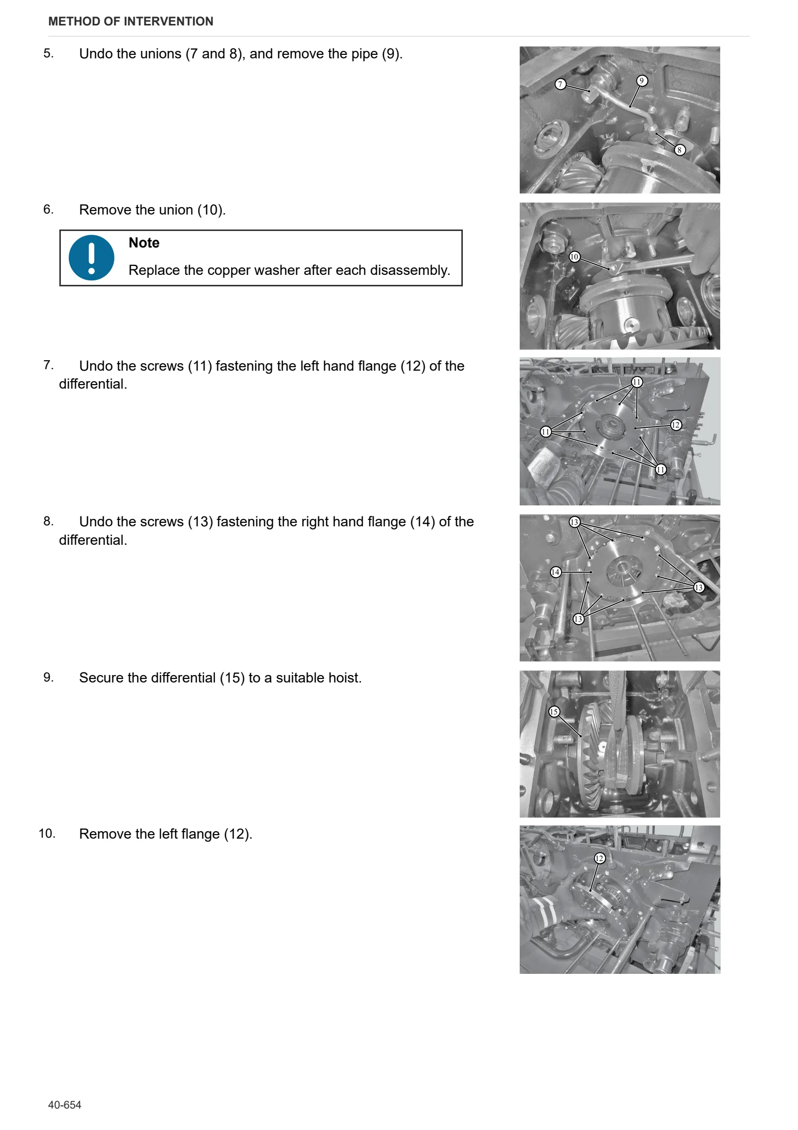
- Removing rear differential
- Controlling and adjusting the clearance of the teeth on the pinion and the differential crown wheel
F0 – Front axle
- Dual traction shaft (DT)
- Support with front axle
- Carrier with front axle
- Adjusting front carrier – engine alignment
- Steering bar/tie-rod
- Front axle
- Front axle adjusting endfloat
- Steering cylinders
- Removing steering cylinders
- Suspended axle pivot bracket
- Differential assembly
- Disassembly of the differential locking device
- Disassembling the differential assembly – pinion
- Adjusting differential preload and pinion-crown wheel backlash
- Pinion positioning and preload adjustment
- Planetary reduction gearbox
- Disassembly of the planetary reduction gearbox
- Steering knuckle casing and axle shaft
- Adjustment of steering knuckle casing and axle shaft
- Front axle brake discs
G0 – Bodywork – Cab – Platform
- Steering wheel
- Instrument cluster
- Instrument cluster
- A/C unit
- Engine hood and front hood panels
- Battery mount
- Cab
- Cab access steps
- Front mudguard
- Left hand side cab trim
- Empty and charge the air conditioning system
- Air conditioning condenser
- Dehydrator filter
- Gear lever
- Gear lever Bowden cable
- Range shift lever
H0 – Hydraulic system
- Load Sensing (LS) ancillary pump
- Lubrication pump
- Disassembling the lubrication pump
- Power steering pump
- Supplementary pump
- Hydrostatic steering (orbitrol)
- Rear auxiliary utility distributors and rear lift
- Front axle suspension solenoid valve block
- Trailer braking valve
N0 – Front lift
- Front top link
- Front lift
R0 – Rear lift
- Complete rear lift
- Disassembling the rear lift
- Lift bushes
- Rear lift control distributor
S0 – Wheels
- Rear wheel
- Front Wheels
Wiring diagrams
Wiring harnesses
- Wiring looms
Service Info
A0 – TRACTOR
- Diagnostics 2026 subscription
- SERVICE NEWS – TTV SERIES – CRUISE CONTROL BEHAVIOUR
- After-sales 2026 subscription
- SERVICE NEWS RESEARCH GUIDE
- Diagnostics 2025 subscription
- After-sales 2025 subscription
- Diagnostics 2024 subscription
- After-sales 2024 subscription
B0 – ENGINE
- TURBOCHARGER VGT MALFUNCTION
C0 – ENGINE ACCESSORIES
- Diagnostic protocol – AdBlue – Float level unit
- Filter and prefilter tool p/n 5.9035.865.0
- SCR AREA DAMAGED SENSORS
D0 – TRANSMISSION
- Wrong dimension on RPTO stub shaft 21 splines 1-3/8″
- PINION NUT LOOSENING
F0 – FRONT AXLE
- 4WD CARDAN SHAFT WEAR
- Bevel gear set loosing screws
H0 – HYDRAULIC AND PNEUMATIC SYSTEM|
- SERVICE NEWS – Front suspension malfunction
- Hydraulic CUNA trailer braking kit (ITALY)
- Single connection hydraulic braking kit availability update – only for EUROPEAN market
L0 – ELECTRIC AL SYSTEM
- SERVICE NEWS – Software package release 2026-02
- FAS SENSOR BRACKET BENT
- SerDia4.0
- iMonitor software HORIZON 5.02
- Regeneration start issue
- iMonitor SW upgrade
- PTO switch not working
V1 – AFTERMARKET KITS
- SERVICE NEWS – Antenna Predisposition
- Check correct installation of braking KIT
- Instructions for kit aftersales