Document overview
Workshop Manual PDF for DEUTZ FAHR 6060 → 14885, 6000 (2012) family. Document language: English; 911 pages.
The corresponding English table of contents contains 21 sections and 277 individual topics.
Main sections included
- Introduction
- General information
- Engine
- Engine accessories
- Pivot points
- Belts and chains
- Hydraulic system
- Feed passage
- Electrical equipment
- Threshing unit
- Cleaning unit
- Service Info
Document details
- Brand: DEUTZ FAHR
- Family: 6000 (2012)
- Model: 6060
- Starting serial number: 14885
- Document type: Workshop Manual
- Language: English
- Pages: 911
- File size: 58.42 MiB
- Format: Digital PDF download
Compatibility
Before purchasing, verify that your machine model and reference code match DEUTZ FAHR 6060 → 14885.
Complete table of contents
Introduction
- Introduction
- General safety instructions
- Safety instructions – maintenance and repair
- Tightening Torques
General information
- Wheel rim to hub screws and nuts tightening torques
- Conversion tables
- Tightening values, screwing classes
- Lubricants
- Seal materials
- One-component adhesive
- Maintenance and inspection schedule
- Oil quantity and quality
- Approved list of lubricating oil quality class – DEUTZ
- Components working speed
- Securing bush support tightening values
- Check the tension of the belts and chains on the LH side
- Check the tension of the belts and chains on the RH side
- Maintenance and repair
- Care and maintenance
- Special tools
- Components of the TCD 2012 L04/L06 4V DCR engine
- Technical data of Engine TCD 2012 4V
- Tightening requirements TCD 2012 L04/L06 4V DCR (Lv.2) engine
- Tightening requirements TCD 2012 L04/L06 4V DCR (Lv.3) engine
Engine
- Tools for engine disassembly and reassembly
- Workshop tools for engine disassembly and reassembly
- Removing and installing the crankcase bleeding
- Removing and installing torsional vibration damper
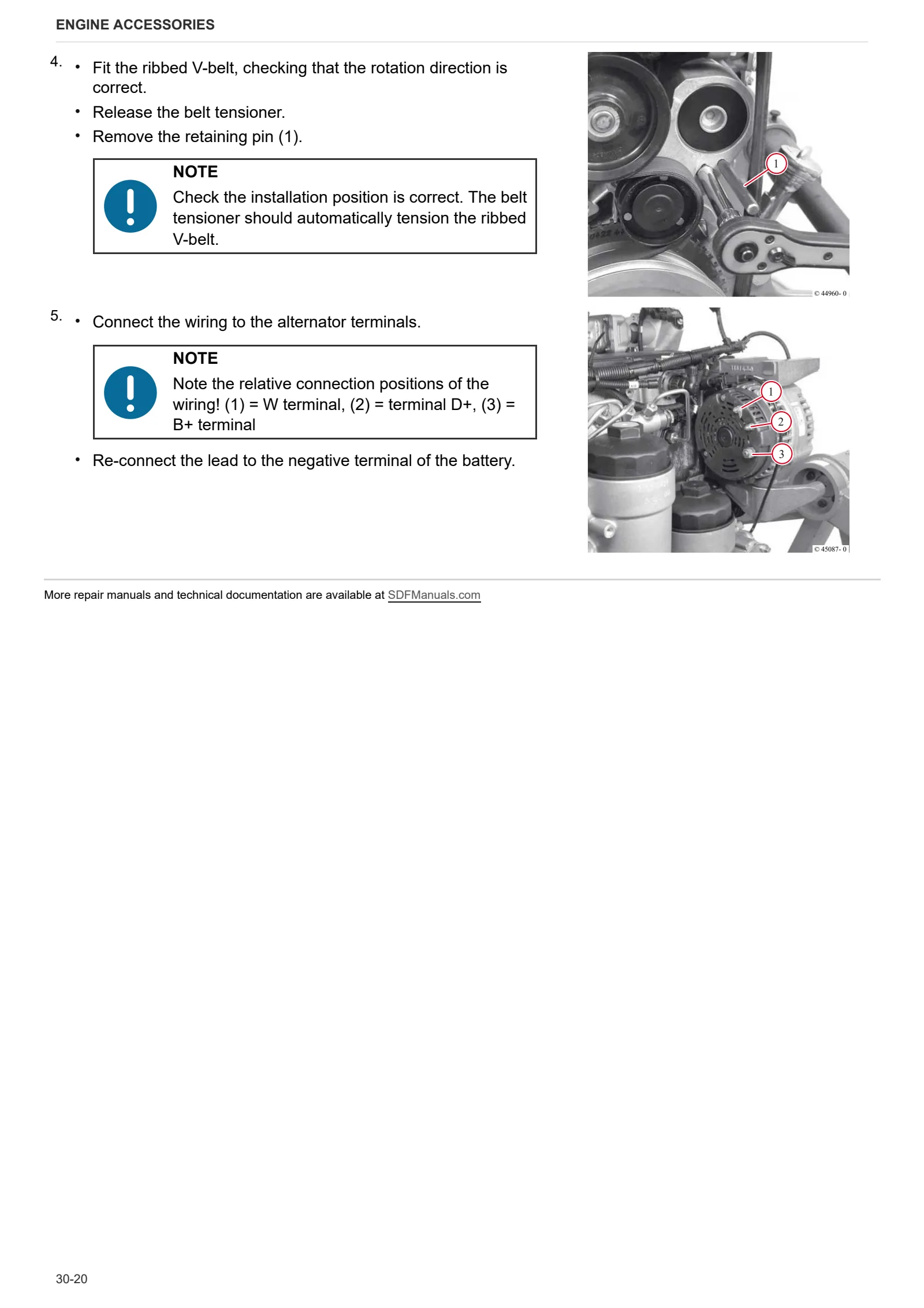
- Alternator, fuel pump, coolant pump and fan drivebelt
- Removing and installing the flywheel
- Removing and installing the belt tensioner (V-rib belt)
- Air conditioning compressor drivebelt
- Air conditioning compressor drivebelt tensioning
- Checking piston overhang
- Removing and installing the rocker arm housing
- Disassembling, assembling and checking the rocker arm and rocker arm bracket
- Checking and setting the valve clearance
- Changing the engine oil
- Checking that the radiator is clean
- Removing and installing the cooler (exhaust gas recirculation)
- Removing and installing the flutter valve (exhaust gas return)
- Checking the coolant thermostat when uninstalled
- Removing and installing the fan drive
- Removing and installing the actuator (exhaust gas return)
- Removing and installing the exhaust line
- Removing and installing the shutoff valve (exhaust gas recirculation)
- Compression test
- Setting the shut-off valve (exhaust return)
- Removing and installing the turbocharger
- Assembly and disassembly of the engine on the assembly stand
- Adjustment of valve clearance
- Fitting and removing rocker seat
- Removing and refitting rocker seat, checking
- Disassembly and assembly of the cylinder head
- Measuring piston protrusion
- Valve assembly and disassembly
- Valve check
- Check the valve guide
- Check the valve residual
- Test data and settings
- Check the endfloat of the crankshaft
- Check the crankshaft
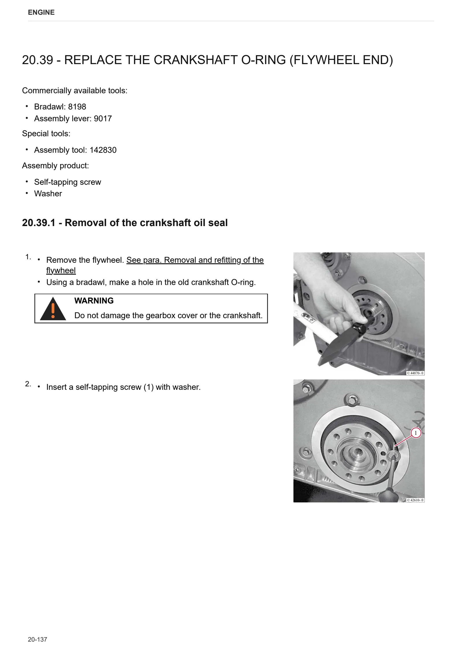
- Replace the crankshaft O-ring (flywheel end)
- Replacing the crankshaft O-ring (opposite end to flywheel)
- Check the connecting rod drum
- Assembly and disassembly of the crankshaft
- Disassembly and assembly of the piston and connecting rod drum
- Check the piston
- Check the piston rings and piston grooves
- Assembly and disassembly of piston cooling nozzles
- Removal and refitting of the crankcase breather
- Check the cylinder
- Removal and refitting of the front cover (opposite end to flywheel)
- Disassembly and assembly of the gear case cover
- Assembly and disassembly of the camshaft
- Check the camshaft
- Removal and refitting of the rotation device
- Removal and refitting of the heater
- Removal and refitting of the turbocharger
- Removing and fitting the butterfly valve (exhaust gas recovery)
- Removing and fitting the cooler (exhaust gas recovery)
- Removing and fitting regulator unit (exhaust gas recovery)
- Removing and fitting the cutoff valve (exhaust gas recovery)
- Adjusting the cutoff valve (exhaust gas recovery)
- Removing and fitting the fuel delivery pump (driven by ribbed V-belt) (L3)
- Removal and refitting of the fuel control unit
- Removal and refitting of the high-pressure pump (installation position A)
- Removal and refitting of the high-pressure pump (installation position B)
- Removal and refitting of the common rail
- Removal and refitting of the injectors
- Removal and refitting of the pressure cut-off valve
- Removal and refitting of the oil sump pan.
- Removal and refitting of the oil pickup pipe
- Removal and refitting of the oil cooler
- Removal and refitting of the lube oil cooler housing
- Removal and refitting of the water pump
- Testing the thermostat (after removal)
- Removal and refitting of the fan drive system
- Removal and refitting of the fan drive system
- Removal and refitting of the torsional vibration damper
- Removing and fitting belt tensioner (ribbed V-belt)
- Removal and refitting of the flywheel
Engine accessories
- Installing flange joint
- Disassembly and assembly of the speed indicator (crankshaft)
- Removal and refitting of the camshaft speed sensor
- Removal and refitting of the exhaust manifold
- Removal and refitting of the fuel filter head.
- Removal and refitting of the rail pressure sensor
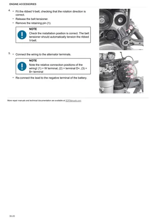
- Removing and fitting the alternator (driven by ribbed V-belt) (L3)
- Disassembly and assembly of the starter
- Remove and install the heating flange
- Removal and refitting of the supply air pressure/temperature sender
- Removing and installing the fuel supply pump
Pivot points
- Safety instructions for tyres and wheel studs
- Brakes, brake fluid safety instructions
- Axles maintenance tables
- Transmission oil check and oil change
- Check and change final drive oil
- Check and change final drive oil – BALANCE
- Braking system
- Tyres and wheel rims
- Front axle
- Front axle – BALANCE version
- Transmission ZNK 25 – 1604 0895/20
- Transmission fork adjustment – transmission ZNK25 – 1604 0895/20
- Transmission control linkage
- Final drive
- Steering axle
Belts and chains
- Drive belts and chains
- Electrical drive of belt clutches, overview
- Powershift control unit (CCP2)
- Straw chopper clutch
- Grain tank discharge clutch
- Threshing section clutch
- Feed passage clutch
- Diagram of lubrication control valve lines
- Diagram of centralised lubrication system lines
Hydraulic system
- Machine hydraulic system
- Harvester hydraulic system – Basic version
- Harvester hydraulic system – Version with lateral tilt adjustment
- Harvester hydraulic system – Version with grain tank extension
- Harvester hydraulic system – Version with grain tank extension and lateral tilt adjustment
- Harvester hydraulic system – Version with cutting angle adjustment and lateral tilt adjustment
- Harvester hydraulic system – Version with grain tank extension, cutting angle adjustment and lateral tilt adjustment
- Harvester hydraulic circuit connection diagram
- Harvester hydraulic circuit connection diagram
- Balance hydraulic system
- Balance circuit connection diagram
- Self levelling system (Balance) control
- General warnings
Feed passage
- Feed passage
- Feed passage – slipping clutch
- Feed passage – stabiliser shaft for feed chain
- Engagement of the feed passage
- Protection against clogging of feed passage
- Protection against clogging between feed channel chain sprockets
- Feed passage reversal device
- Feed passage oscillating frame, orientable adapter
Electrical equipment
Components
- 2.8519.074.0/20 – HLHP control unit
- 16050210 – “DAVID” CAN module (A13)
- 16057402 – CAN module (A25)
- 16057402 – CAN module (A27)
- 04214367 – Engine control unit
- A – Starting and charging
- B – Fuses
- C – Grounds
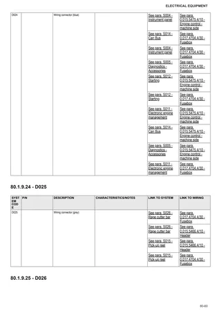
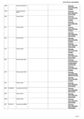
- D – Intermediate connections
- E – On-board instruments and visual and audible indicators
- F – External lights
- G – Interior lights
- H – Electrical and manual controls
- I – Circuit breakers
- J – Relays
- K – Sensors and transmitters
- L – Electromagnets and solenoid valves
- M – Electrical/electronic devices, flasher units and timers
- N – Electric motors and actuators
- O – Resistors, rheostats, diodes and diode boards
- P – Various services
- Q – Safety devices
- R – Diagnostics
- T – Power supply points (+15 o +30)
- Commander Control 2000 CAN-Bus with on-board monitor schematic
- Switches and sensors used by the Commander Control 2000
- Calibration of Auto Control system
- Cutter bar float control sensors
- Cutter bar float control sensors
- Header position sensors – Installation
- On-board monitor and Commander Control 2000: overview of control and monitoring functions
- Cutter bar electronic control
Systems
- S012 – Power supply (+15)
- S003 – Power supply (+30)
- S004 – Instrument panel
- S005 – Diagnostics – Accessories
- S006 – Lights
- S007 – Work lights
- S008 – Brakes
- S009 – Manual air conditioner
- S010 – Windscreen wipers
- S011 – Electronic engine management
- S012 – Starting
- S013 – Transmission
- S014 – Can Bus
- S015 – Pick-up reel
- S016 – Header float, lateral rotation and cutting angle
- S016a – Header float, lateral rotation and cutting angle with balance
- S017 – Feed passage reverser
- S018 – Threshing unit
- S019 – Straw walker
- S020 – Sieves
- S021 – Straw chopper
- S022 – Spreader deflectors
- S023 – Grain tank
- S024 – Grain tank discharge pipe
- S025 – Lubrication system
- S026 – Rape cutter bar
- S027 – Balance
WIRING HARNESSES
- 0.015.5464.4/10 – Starter motor – Alternator
- 0.015.5466.4/10 – Header
- 0.015.5467.4/40 – Balance controller
- 0.015.5475.4/10 – Engine control – machine side
- 0.015.7162.4 – Roof lights
- 0.016.1616.4 – Balance system main solenoid valve
- 0.016.6222.4/10 – Frame
- 0.016.6617.4/10 – Straw walker sensors
- 0.017.4577.4/10 – Front wiring loom
- 0.017.4579.4/10 – Electric motors
- 0.017.4580.4/20 – Grain tank
- 0.017.4582.4/30 – Engine interface
- 0.017.4700.4/10 – Grain tank work lights
- 0.017.4704.4/30 – Fusebox
- 0.017.4990.4/10 – Solenoid valves block
- 0.017.5019.4/10 – Rear wiring loom
- 0.017.5023.4 – RH rear light
- 0.017.5023.4 – LH rear light
- 0.017.5043.4/20 – Side console
- 0.017.5055.4/20 – Roof
- 0.017.5623.4 – Front handrail worklights
- 0.017.5671.4 – Maintenance worklights
- 0.017.6835.4 – Fusebox earth
- 0.019.0691.4 – Pedals switch
- 0.019.0697.4 – Battery wiring
- 0.019.0725.4/10 – Operator seat safety system
- 04214410 – Engine injectors
- 04216076 – Engine control – Engine side
- 04215317 – Engine control – Machine side
- 04216250 – Starter motor control relay
- 16050256/10 – Spreader deflectors adjustment
- 16050268 – LH threshing drum door emergency switch
- 16050274/10 – Sieve box worklight
- 16058810 – Climate control
- 16062550 – Feed passage reverser
- 16062566/20 – Lower sieve adjustment motor
- 16062567/20 – Upper sieve adjustment motor
- 16062568/10 – Cutting angle sensor
- 16062623 – Frame earth
Calibrations and diagnostics
- Control functions of the Commander Control 2000
- Alarms – Cutting bar ECU
- Engine ECU Alarms: SPN 000016-000175
- Engine ECU Alarms: SPN 000190-001188
- Engine ECU Alarms: SPN 001231-003520
- Engine ECU Alarms: SPN 003532-005763
- Engine ECU Alarms: SPN 520521-523632
- Engine ECU Alarms: SPN 523633-523918
- Engine ECU Alarms: SPN 523919-524030
- Engine ECU Alarms: SPN 524031-524108
- Engine ECU Alarms: SPN 524109-524267
Threshing unit
- Installing concaves
- Turbo separator adjustment
Cleaning unit
- Straw walker mounts
- Fitting straw walker pulleys and belt tensioners
Service Info
C0 – ENGINE ACCESSORIES
- Filter and prefilter tool p/n 5.9035.865.0
- Cleaning fan bearing breakage
HB – AXLES
- Adjusting rear axle toe angle
HH – ELECTRICAL SYSTEM
- Linear actuator
HL – CLEANER UNIT
- Straw walker supports assembly procedure
HM – GRAIN TANK / ELEVATOR
- Elevator and head chain tensioning