
Document overview
Workshop Manual for SAME LASER³ 140 → ZKDY0102W0TS1001 from the LASER³ family. Digital PDF in English with 637 pages.
The corresponding English table of contents contains 34 sections and 158 individual topics.
Main sections included
- Introduction
- Safety
- Technical characteristics
- Calibrations and electronic diagnosis
- Wiring diagrams
- Service Info
Document details
- Brand: SAME
- Family: LASER³
- Model: LASER³ 140
- Starting serial number: ZKDY0102W0TS1001
- Document type: Workshop Manual
- Language: English
- Pages: 637
- File size: 62.35 MiB
- Format: Digital PDF download
Compatibility
Before purchasing, verify that your machine model and reference code match SAME LASER³ 140 → ZKDY0102W0TS1001.
Complete table of contents
Introduction
- Introduction – Engines
- Tightening Torques
- Tightening torques for nuts and bolts of electrical connections
- Wheel rim to hub screws and nuts tightening torques
- Installation of solenoid valves and cartridge valves
- Installation of quick couplers
- Units of measurement and conversion factors
- Injector type identification
Safety
Preface
- Important notes concerning safety
Important safety information
- Recognising hazards
- Indications for persons in contact with the tractor
Safety rules
- Risks during tractor preparation
- Risks during maintenance
- Work on machine systems
- Special disassembly/assembly/inspection procedures
Safety pictograms
- Replacing safety pictograms
Environmental risks
- Hazards associated with the operating environment
Technical characteristics
Transmission
- Transmission
- Clutch
- Range gearbox and rear PTO
Rear axle
- Adjustment of the Rear Bevel Gear Pair
- Rear axle
Front axle
- Front axle
Bodywork – Cab – Platform
- Accelerator pedal
- Changes of the state of matter
Hydraulic system
- Pump tightening torques
- Solenoid valves and cartridge valves
- Steering control valve pipes
- Hydraulic system
- PTO circuit hydraulic diagram
- Brakes, power lift and remote valves circuit
- Hydraulic pumps
- Power steering valve
- Remote control valves
- Braking system
- Trailer braking valve (ITALY version)
- Trailer braking valve (ITALY version)
Electrical equipment
- Battery
- Alternator
Rear lift
- Rear lift control valve
Calibrations and electronic diagnosis
Diagnostic tools
- Positions of ECUs and diagnostic instruments
- ECU interrogation
SDF Analyser
- SDF Analyser
- SDF Analyser – Diagnostic socket connection
Diagnostic tool screens
- Operator seated sensor ECU (p/n 2.8519.106.0)
- PC Tester Screens – Engine ECU – Structure
Commissioning and calibrating the tractor
- Commissioning – Engine ECU – Presentation screen
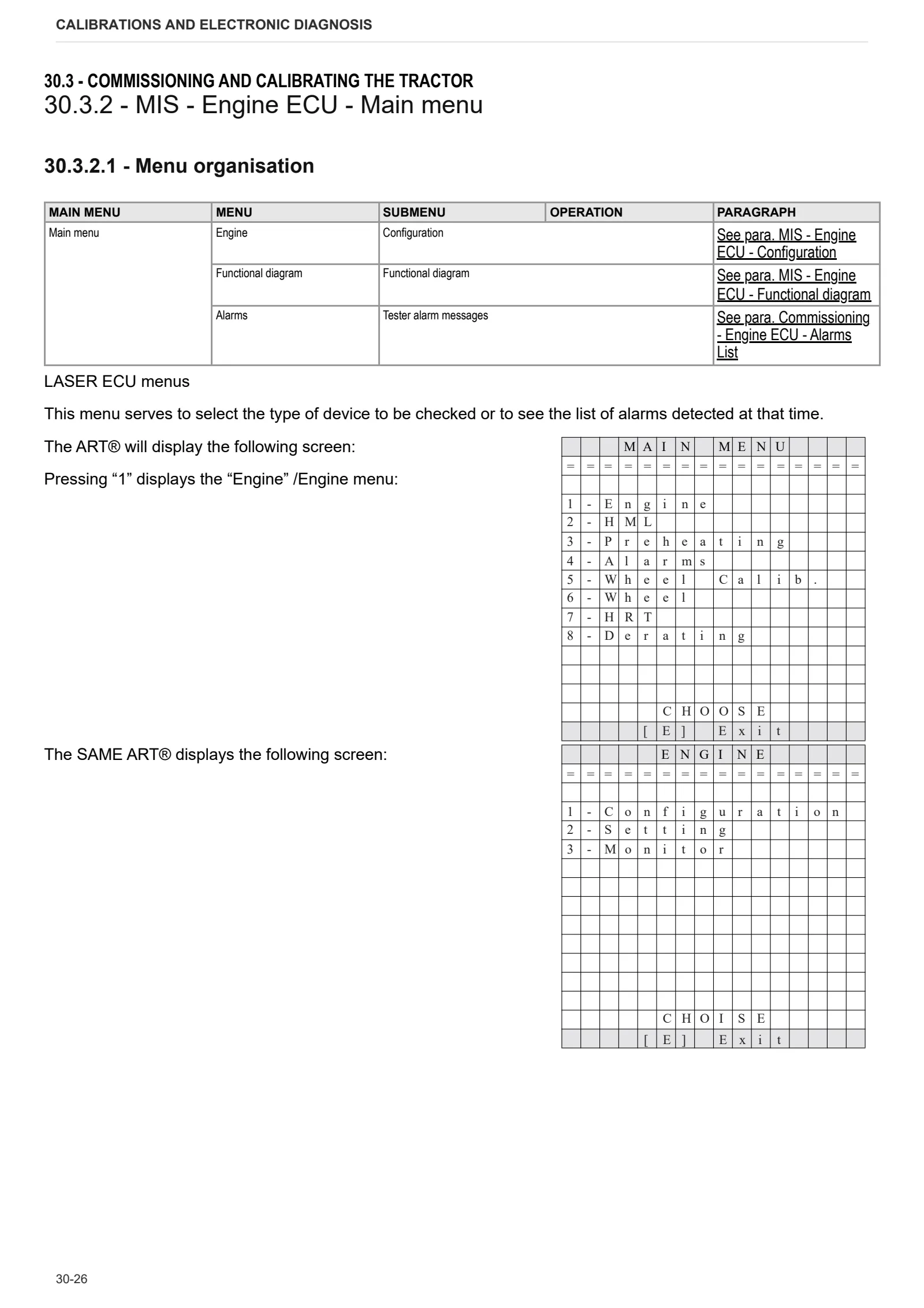
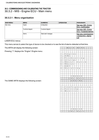
- MIS – Engine ECU – Main menu
- MIS – Engine ECU – Configuration
- Commissioning – Engine ECU – Engine menu
- Commissioning – Engine ECU – HML menu
- Commissioning – Engine ECU – Preheating menu
- Commissioning – Engine ECU – Alarms Menu
- Commissioning – Engine ECU – Alarms List
- Commissioning – Engine ECU – Wheel Calibration Menu
- Commissioning – Engine ECU – Wheels menu
- Commissioning – Engine ECU – HRT Menu
- Commissioning – Engine ECU – DERATING Menu
- Commissioning – Engine ECU – Engine type config.
- Commissioning – Engine ECU – Engine type config.
- MIS – Engine ECU – Functional diagram
- Commissioning – Engine ECU – Functional diagram
Wiring diagrams
Introduction
- Introduction
- Basic electronics for mechanics (1/2)
- Basic electronics for mechanics (2/2)
- Electrical and electronic components (1/2)
- Electrical and electronic components (2/2)
Components
- A – Starting and charging
- B – Valves and fuses box
- C – Earths
- D – Intermediate connections
- E – On-board instruments and visual and audible indicators
- F – External lights (rotating beacon)
- G – Interior lights
- H – Manual electrical controls (steering column switch)
- I – Switches
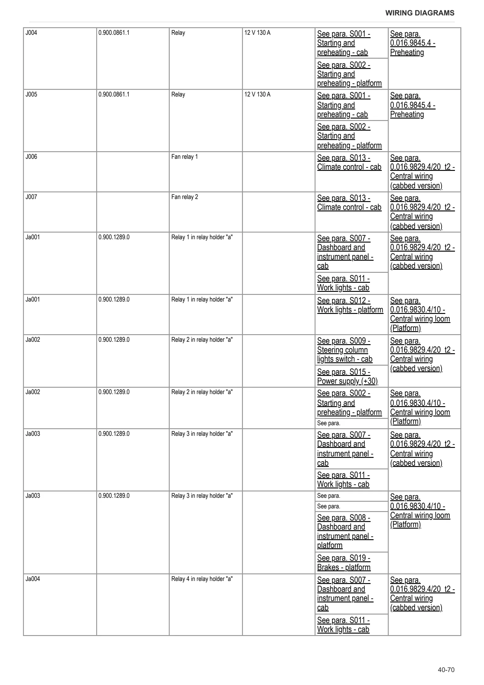
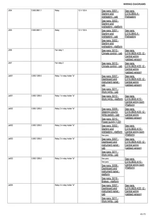
- J – Relays
- K – Sensors and transmitters
- L – Electromagnets and solenoid valves
- M – Electrical/electronic devices, flasher units and timers
- N – Electric motors and actuators
- O – Resistors and rheostats
- P – Various services
- Q – Safety devices
- R – Diagnostics
Systems
- S001 – Starting and preheating – cab
- S002 – Starting and preheating – platform
- S003 – Electronic engine governor – cab
- S004 – Electronic engine governor – platform
- S005 – Transmission – cab
- S006- Transmission – platform
- S007 – Dashboard and instrument panel – cab
- S008 – Dashboard and instrument panel – platform
- S009 – Steering column lights switch – cab
- S010 – Steering column lights switch – platform
- S011 – Work lights – cab
- S012 – Work lights – platform
- S013 – Climate control – cab
- S014 – Power supply (+15)
- S015 – Power supply (+30)
- S016 – PTO – cab
- S016 – PTO – platform
- S018 – Brakes – cab
- S019 – Brakes – platform
- S020 – Windscreen wipers – cab
Wiring harnesses
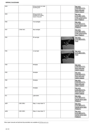
- 0.016.9834.4/20 – Front
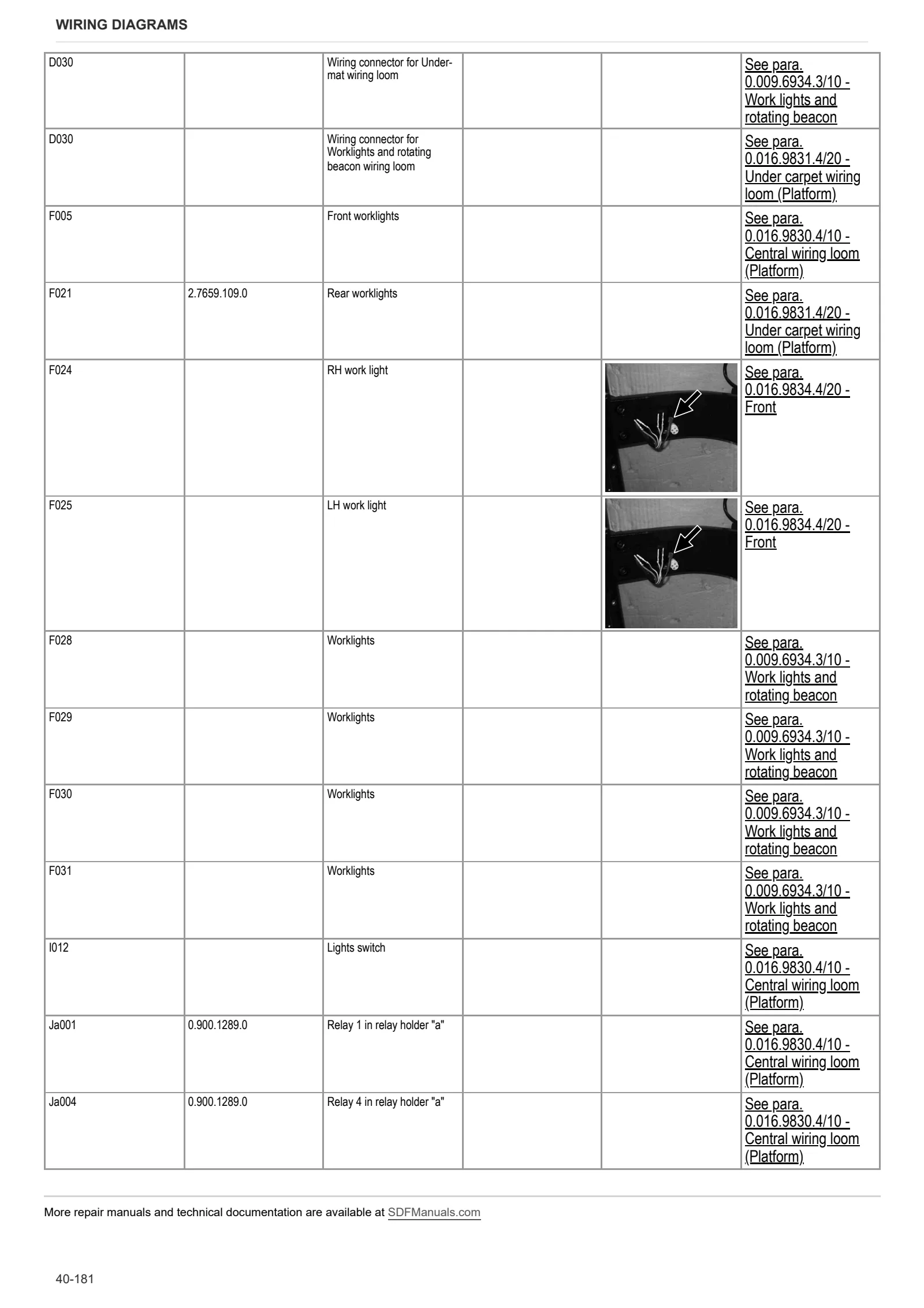
- 0.009.6934.3/10 – Work lights and rotating beacon
- 0.255.8454.3/20 – Number plate light wiring
- 0.011.3824.4/10 – Rotating beacon
- 0.013.9827.4/90 – Roof
- 0.014.3927.4/40 – Front work light
- 0.014.8355.4/20 – Work light
- 0.016.9826.4/20 – Rear wiring
- 0.016.9827.4/20 – Under mat (cabbed version)
- 0.016.9829.4/20_t2 – Central wiring (cabbed version)
- 0.016.9829.4.20 – Instrument panel
- 0.016.9830.4/10 – Central wiring loom (Platform)
- 0.016.9831.4/20 – Under carpet wiring loom (Platform)
- 0.016.9832.4/10 – Engine (cabbed version)
- 0.016.9833.4/10 – Engine (platform version)
- 0.016.9837.4 – Fuel pre-filter wiring
- 0.016.9839.4 – Hydraulic trailer braking wiring loom – ITALY
- 0.016.9840.4 – Air trailer braking wiring loom – GERMANY
- 0.016.9841.4 – Air braking
- 0.016.9845.4 – Preheating
Service Info
A0 – TRACTOR
- Diagnostics 2026 subscription
- After-sales 2026 subscription
- SERVICE NEWS RESEARCH GUIDE
- Diagnostics 2025 subscription
- After-sales 2025 subscription
- Diagnostics 2023 subscription
- Diagnostics 2024 subscription
- Diagnostics 2022 subscription
- Diagnostics 2021 subscription
- After-sales 2024 subscription
- After-sales 2023 subscription
- After-sales 2022 subscription
- After-sales 2021 subscription
- After-sales 2019 subscription
- SDF Parts and SDF Service DVV 04/2014, version 26
- New function: Download PDF manuals
- Diagnostics – 2020 subscription
- After-sales – 2020 subscription
- After-sales – 2018 subscription
- Service and Spare Parts – 2017 Subscription
- SDF Parts and SDF Service DVDs 05/2014 version 25
- SDF Parts and SDF Service DVDs 03/2013 version 24
B0 – ENGINE
- Flushing the lubrication circuit
- Deutz AG engine oil specifications
C0 – ENGINE ACCESSORIES
- Diagnostic protocol – AdBlue – Float level unit
- Filter and prefilter tool p/n 5.9035.865.0
D0 – TRANSMISSION
- Extremely stiff range selector
- Main clutch disc
F0 – FRONT AXLE
- Check the front axle steering knuckles for wear
- Steering behavior check procedure
G0 – BODYWORK – CAB
- Air conditioning system recharging
H0 – HYDRAULIC AND PNEUMATIC SYSTEM|
- Hydraulic CUNA trailer braking kit (ITALY)
- Single connection hydraulic braking kit availability update – only for EUROPEAN market
- L0 – ELECTRIC AL SYSTEM