Document overview
Workshop Manual for SAME 2012 L04 2V UPS Stage 3A from the Tractor components – Engine – DEUTZ AG Stage 3 family. Digital PDF in English with 281 pages.
The corresponding English table of contents contains 9 sections and 81 individual topics.
Main sections included
- Introduction
- Technical characteristics
- Calibrations and electronic diagnosis
- Method of intervention
Document details
- Brand: SAME
- Family: Tractor components – Engine – DEUTZ AG Stage 3
- Model: 2012 L04 2V UPS Stage 3A
- Document type: Workshop Manual
- Language: English
- Pages: 281
- File size: 17.96 MiB
- Format: Digital PDF download
Compatibility
Before purchasing, verify that your machine model and reference code match SAME 2012 L04 2V UPS Stage 3A.
Complete table of contents
Introduction
- Introduction – Engines
Technical characteristics
Engine
- Components of the 2012 2V UPS engine
- Test data and settings
- Tightening requirements 2012 2V UPS engine
Calibrations and electronic diagnosis
Diagnostic tools
Serdia 2000
- SERDIA 2000 level III” software
Method of intervention
- Tools for engine disassembly and reassembly
- Workshop tools for engine disassembly and reassembly
- Tightening Torques
B0 – Engine
- Air conditioning compressor drive belt
- Tension adjustment of the fan and air conditioning compressor drive belt
- Alternator, fuel pump and water pump drive belt
- Tension adjustment of the alternator, fuel pump and water pump drive belt
- Compression test
- Assembly and disassembly of the engine on the assembly stand
- Adjustment of valve clearance
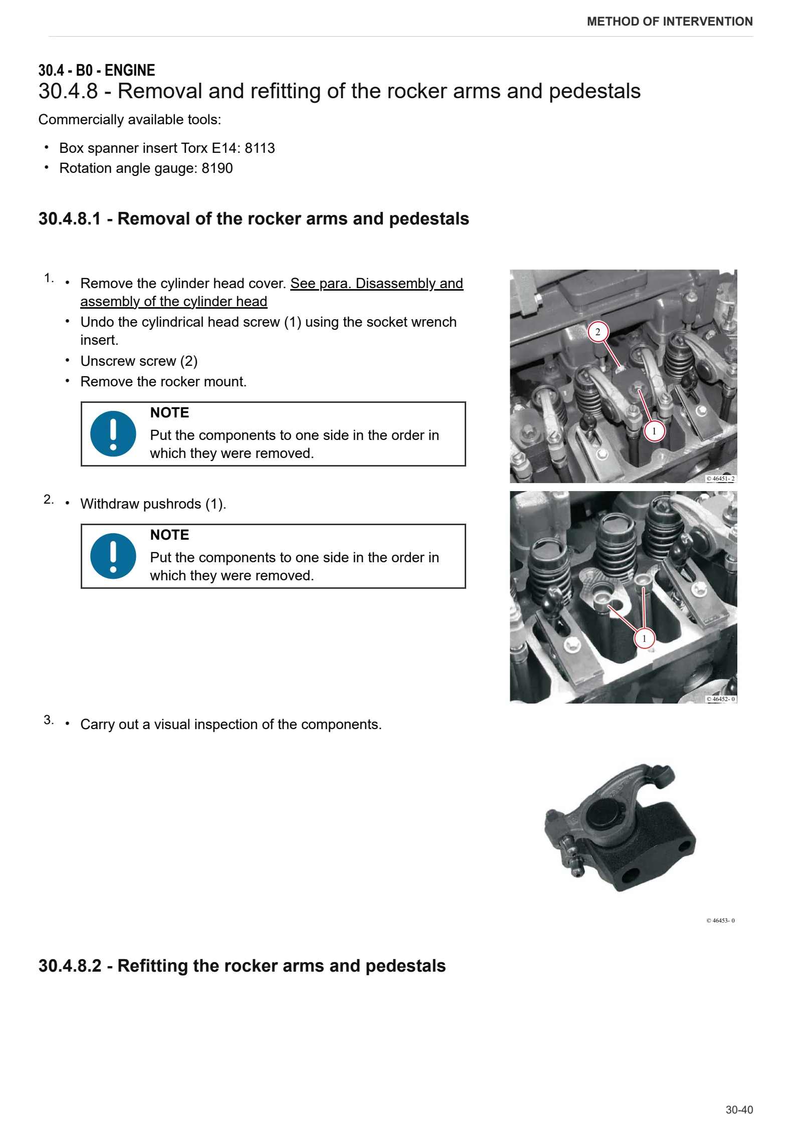
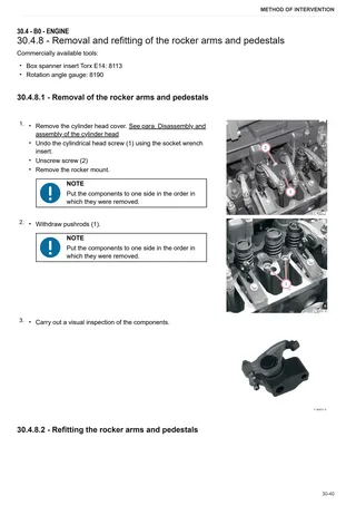
- Removal and refitting of the rocker arms and pedestals
- Disassemble and complete the rocker and support, check
- Disassembly and assembly of the cylinder head
- Grinding the cylinder head seal surface
- Measuring piston protrusion
- Valve assembly and disassembly
- Valve check
- Check the valve guide
- Replacing the valve guide (oversized – cast)
- Check the valve residual
- Replacing the lined valve seat (oversized)
- Check the endfloat of the crankshaft
- Check the crankshaft
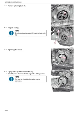
- Replace the crankshaft O-ring (flywheel end)
- Replacing the crankshaft O-ring (opposite end to flywheel)
- Check the connecting rod drum
- Fitting and removing piston pin bush
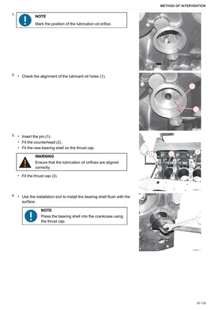
- Assembly and disassembly of the crankshaft
- Fitting and removing counterweight shafts, checking
- Disassembly and assembly of the piston and connecting rod drum
- Check the piston
- Check the piston rings and piston grooves
- Assembly and disassembly of piston cooling nozzles
- Removal and refitting of the crankcase breather
- Check the cylinder
- Removal and refitting of the front cover (opposite end to flywheel)
- Disassembly and assembly of the connector box
- Fitting and removing the camshaft bearings, checking
- Disassembly and assembly of the gear case cover
- Assembly and disassembly of the camshaft
- Check the camshaft
- Removal and refitting of the rotation device
- Removing and fitting the V-belt pulley
- Fitting, removing, checking and setting adjuster rod
- Removal and refitting of the turbocharger
- Removal and refitting of the charge air duct
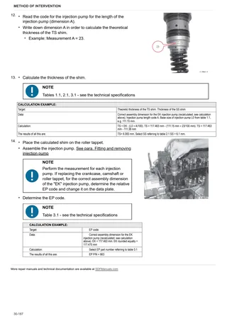
- Fitting and removing injection pump
- Determine the thickness of the shim (engine without injection advance variator)
- Determine the thickness of the shim (engine with injection advance variator)
- Determination of the overall dimensions of the injection pump (engine without the injection advance variator)
- Determination of the overall dimensions of the injection pump (engine with the injection advance variator)
- Fitting and removing injection valves
- Checking the injection valves
- Removal and refitting of the fuel lift pump
- Removal and refitting of the oil pickup pipe
- Removing and fitting the lubricant oil sump pan (cast iron lubricant oil sump)
- Disassembly and assembly of the lubricant oil sump (lubricant oil sump-plate)
- Removal and refitting of the oil cooler
- Disassembly and assembly of the oil radiator housing
- Removal and refitting of the oil pressure switch
- Removal and refitting of the water pump
- Removal and assembly of the fan support
- Removal and refitting of the fan support
- Removal and refitting of the flywheel
- Replacing the starter motor ring gear on the flywheel
C0 – Engine accessories
- Starter motor
- Removal and refitting of the thermostat
- Testing the thermostat (after removal)
- Removal and refitting of the heater
- Removing and fitting the engine governor
- Removal and refitting of the exhaust manifold
- Removal and refitting of the fuel filter head.
- Assembly and disassembly of the temperature sender
- Removal and refitting the engine block
- Removal and refitting of the alternator (with drivebelt)
- Disassembly and assembly of the starter