Document overview
Workshop Manual for LAMBORGHINI NITRO 110 T4i VRT → ZKDY900200TL10001 from the NITRO T4i VRT (STAGE 3B) family. Digital PDF in English with 2,106 pages.
The corresponding English table of contents contains 61 sections and 609 individual topics.
Main sections included
- Introduction
- Safety
- Technical characteristics
- Calibrations and electronic diagnosis
- Method of intervention
- Wiring diagrams
- Service Info
Document details
- Brand: LAMBORGHINI
- Family: NITRO T4i VRT (STAGE 3B)
- Model: NITRO 110 T4i VRT
- Starting serial number: ZKDY900200TL10001
- Document type: Workshop Manual
- Language: English
- Pages: 2,106
- File size: 363.37 MiB
- Format: Digital PDF download
Compatibility
Before purchasing, verify that your machine model and reference code match LAMBORGHINI NITRO 110 T4i VRT → ZKDY900200TL10001.
Complete table of contents
Introduction
- Units of measurement and conversion factors
- Tightening Torques
Safety
Preface
- Important notes concerning safety
Important safety information
- Recognising hazards
- Indications for persons in contact with the tractor
Safety rules
- Risks during tractor preparation
- Risks during maintenance
- Work on machine systems
- Special disassembly/assembly/inspection procedures
Safety pictograms
- Replacing safety pictograms
Environmental risks
- Hazards associated with the operating environment
Technical characteristics
Engine
- Motor description – construction type
- Engine description – Views of engine
- Engine description – Lubricant oil diagram
- Engine description – Fuel circuit diagram
- Engine description – Coolant diagram
- Engine description – Exhaust gas recovery
- Engine description – Exhaust gas after-treatment
- Engine description – Electrical/electronic system
- Usage – Starting procedure
- Use – exhaust gas after-treatment systems
- Use – Stop procedure
- Operating materials – lubricant oil
- Operating materials – Fuel
- Operating materials – Coolant
- Care and maintenance work – Fuel distribution system
- Care and maintenance work – Cooling system
- Care and maintenance work – Engine cleaning
- Care and maintenance work – Intake system
- Care and maintenance work – Electrical system
- Malfunctions – Malfunction table
- Faults – Engine management
- Transport and storage – Transport
- Transport and storage – Engine protection treatment
- Technical data – Tools
Engine accessories
- Pressure/temperature sender – Technical data
- Pressure transducer – Technical data
- Pressure sensor – Technical data
- Temperature sender – Technical data
Transmission
- “SDFG” continuously variable transmission
- Mechanical variable ratio transmission
- Transmission
- “Input” clutch
- Variable ratio transmission unit
- Shuttle unit
- Ranges assembly
- Dual traction idler gear
- Pump carrier
Rear axle
- Rear axle
- Rear axle
- Park brake unit
- Rear differential
- Rear wheel carrier
Front axle
- Front axle 2 WD
- Front axle 4 WD
- Mechanical front differential lock
- Disc type front differential lock (ASM)
Bodywork – Cab – Platform
- General introduction to the A/C system
- Changes of the state of matter
- Air conditioning system – General system
- Charging the A/C system
Hydraulic system
- Transmission hydraulic system
- Hydraulic distributor system
- Hydraulic pump unit
- Transfer pump
- Suction pump filter
- Delivery line filter
- 60 l/min. ECO AUX block
- Braking system
- Park Brake system
- Park Brake valve
- Hydraulic Engine Brake
- Power steering 80 -160cc
- Power steering SDD 125-250cc
- Power steering SDD 115-240cc
- Front axle suspension
- Distributors unit – Mechanical version
- Distributors unit – Electrical version
- 3-way priority valve, suspended axle – Mechanical distributor version
- Bistable valve for LS signal, suspended axle – Electronic distributor version
- Rear PTO
- Energy Saving
- Engaging dual traction with ASM
- Hydraulic unit
Front PTO
- Front PTO
Front lift
- Front lift
Rear lift
- Rear lift control valve
Calibrations and electronic diagnosis
Diagnostic tools
SDF Analyser
- SDF Analyser
- SDF Analyser – Diagnostic socket connection
Serdia 2010
- Safety-Hints
- Common Hints
- Common Hints – Start and Communication
- Common Hints – Disposability
- Introduction
- Error Hints (FAQ)
- Connection establishment
- Software handling
- Software handling – Topper elements
- Global Programfunctionality – Dataset management
- Global Programfunctionality – Error memory
- Global Programfunctionality – Graphical display
- Global Programfunctionality – Program adjustments
- UseCases EMR4
- Engine settings
- Adjustments engine speed – acceleration pedal
- CRT – TIER4 interim
- DPF – Burner – TIER4 interim
- SCR – TIER4 interim
- SCRT -TIER4 final
- Service-Cases
- Other
- UseCases EMR3
- UseCases EMR2
- EOL Test (Tier4F)
- SCR service routines
- DPF service routines
- Service Routines DPF (DOC/SCR)
Diagnostic tool screens
- HLHP control unit diagnostics (SW SP272AS) – “TEST” screen for ART/PC Tester
- HLHP control unit diagnostics (SW SP272AS) – “Alarms” screen for ART/PC Tester
- Infocenter
Commissioning and calibrating the tractor
- Purpose and scope of the document
- Instruments and information required
- Description of commissioning procedure
- Eeprom re-initialisation
- Line end programming
- Manual calibration of hydrostatic unit
- Manual calibration of Work and Reverse clutches
- Automatic calibration of rear PTO�
- STOLL READY configuration test
ECU alarms
- ECU alarms
Engine alarms
- Engine ECU Alarms: SPN 000016-000175
- Engine ECU Alarms: SPN 000190-001188
- Engine ECU Alarms: SPN 001231-003520
- Engine ECU Alarms: SPN 003532-005763
- Engine ECU Alarms: SPN 520521-523632
- Engine ECU Alarms: SPN 523633-523918
- Engine ECU Alarms: SPN 523919-524030
- Engine ECU Alarms: SPN 524031-524108
- Engine ECU Alarms: SPN 524109-524267
Fan alarms
- FCU alarms
Transmission alarms
- Transmission alarms
HLHP alarms
- HLHP2 Service ECU alarms “User Control”
- HLHP2 Service ECU alarms “User Control”
AC system alarms
- Manual Air Conditioner Alarms
- Automatic Climate control unit alarms list
Lift alarms
- ECU alarms Lift
Electrohydraulic control valve alarms
- E.H. Distributors Alarms List
Front Loader Alarms
- Front loader alarms
Software management
- Engine dataset upgrade
Method of intervention
- Tools for engine disassembly and reassembly
- Workshop tools for engine disassembly and reassembly (Lv.2)
- Workshop tools for engine disassembly and reassembly (Lv.3)
B0 – Engine
- Separating engine / transmission
- Complete engine
- A/C compressor belt
- Alternator, fuel pump and coolant pump drive belt
- Torsionally flexible coupling and engine flywheel
- Closing components
- Actuating elements
- Removing and fitting the belt tensioner (ribbed V-belt)
- Removing and fitting the console (ribbed V-belt)
- Engine mounting
- Engine mounting
- Engine mounting
- Console
- Removing and fitting hydraulic pump drive
- Removing and fitting the regulator valve
- Blanking cover (PTO-B)
- Assembly and disassembly of the camshaft
- Check the camshaft
- Disassembly and assembly of the control elements
- Fitting and removing rotation/lock tool
- Fitting and removing transition pipe
- Removing and installing the gearcase (Fastening parts)
- Line
- Disassembly and assembly of the connector box
- Disassembly and assembly of the connector box
- Disassembly and assembly of the connector box
- Disassembly and assembly of the connector box
- Disassembly and assembly of the connector box
- Connector casing
- Checking crankcase lubrication pressure
- Blanking tool (crankcase)
- Pipe (crankcase breather)
- Oil pressure regulator valve (shutter valve)
- Valve needle (crankcase breather)
- Removal and refitting of the flywheel (fixing elements)
- Removing and installing the crankshaft (Lv.3)
- Removing and installing crankshaft bearings
- Check the crankshaft bearings
- Assembly and disassembly of the crankshaft bearing
- Check the crankshaft
- Removing and installing the V-belt pulley/V-ribbed pulley
- Removing and fitting the counterweight drive shaft
- V-belt pulley
- V-belt pulley
- Checking the cylinder
- Fitting and removing the piston cooling nozzle
- Disassembling and assembling the sensor wheel
- Removing and refitting the camshaft bearing (camshaft removed from engine)
- Checking the camshaft bearing (camshaft removed from engine)
- Disassembly and reassembly of connecting rod shank
- Check the connecting rod shank
- Removing and fitting pistons (L3)
- Check the piston
- Measuring piston protrusion
- Removing and fitting the piston rings
- Checking piston rings
- Replace the crankshaft O-ring (flywheel end)
- Fitting and removing seal seat
- Replacing the crankshaft seal ring (side opposite flywheel).
- Intermediate gear
- Support
- Compression test (with injectors removed from engine)
- Checking compression value (with glow plugs / screw plugs removed)
- Removal and refitting of the cylinder head cover
- Disassembling and assembling the cylinder head (fasteners)
- Assembly and disassembly of the valves
- Checking valves, valve guides, valve springs and valve recess
- Turbocharger shield plate
- Removal and refitting of the oil sump pan.
- Removing and fitting lubricant oil sump (heavy version)
- Disassembling and assembling the oil suction pipe
- Topping up with oil
- Removing and fitting the lubricant oil radiator
- Lubricating oil filter console
- Fitting the lubricant oil filter (vrankcase)
- Removal and refitting of the lubricating oil pipe (exhaust gas turbocharger)
- Removal and refitting of the lubricating oil pipe (exhaust gas turbocharger)
- Removal and refitting of the lubricating oil return pipe (exhaust gas turbocharger)
- Removal and refitting of the lubricating oil return pipe (exhaust gas turbocharger)
- Removing and fitting the oil pressure regulator valve
- Oil filler neck (crankcase, intake side)
- Removing and refitting the lubricant oil return pipe – upper section – (turbocharger)
- Mount (lubricant oil return line)
- Fitting and removing the high pressure pump
- Removing and fitting the injector
- Removing and fitting the rail
- Removing and fitting the pressure cut-off valve (rail)
- Removing and fitting the rail pressure sensor
- High pressure pump, mating with gear (with gear case disassembled)
- Fitting the fuel pressure transducer
- Fuel delivery pump (electric)
- Fuel pipe (quick connector)
- Removal and refitting of the charge air manifold
- Charge air manifold
- Disassembling and assembling the thermostat
- Checking the thermostat (after removal)
- Line
- Line
- Line
- Removing and fitting the coolant pump
- Pulley (V belt, poly-V belt)
- Intake manifold (turbocharger)
- Connection (crankcase, exhaust gas recovery, coolant pipe)
- Removing and fitting the compensation pipe (exhaust gas recirculation system)
- Pipe (thermostat housing, exhaust gas recovery, coolant pipe)
- Exhaust manifold (turbocharger)
- Exhaust manifold (turbocharger)
- Exhaust manifold (turbocharger)
- Flexible hose (thermostat housing – crankcase)
- Disassembling and assembling the butterfly valve
- Disassembling and assembling the radiator
- Removing and fitting the exhaust gas recirculation valve
- Blanking screw (cooler – thermostat housing coolant pipe)
- Shield plate (exhaust pipe)
- Pipe (radiator – thermostat housing, exhaust gas recirculation system)
- Coolant pipe (radiator – thermostat housing, exhaust gas recovery system)
- Removing and fitting the charge air duct
- Charge air duct
- Removal and refitting of the turbocharger
- Removal and refitting of the turbocharger
- Fastener elements (connector guides – glow plugs)
- Relay, mount (glow plugs)
- Fastener elements (cable harnesses) (thermostat housing – cylinder head)
- Fastener elements (cable harnesses) (hose – thermostat housing – cylinder head)
- Fastener elements (cable harnesses) (thermostat housing – cylinder head)
C0 – Engine accessories
- Changing the coolant and flushing the circuit
- Intercooler, gearbox oil and fuel heat exchangers
- Fuel radiator
- Cooler
- Radiator assembly
- Exhaust pipe
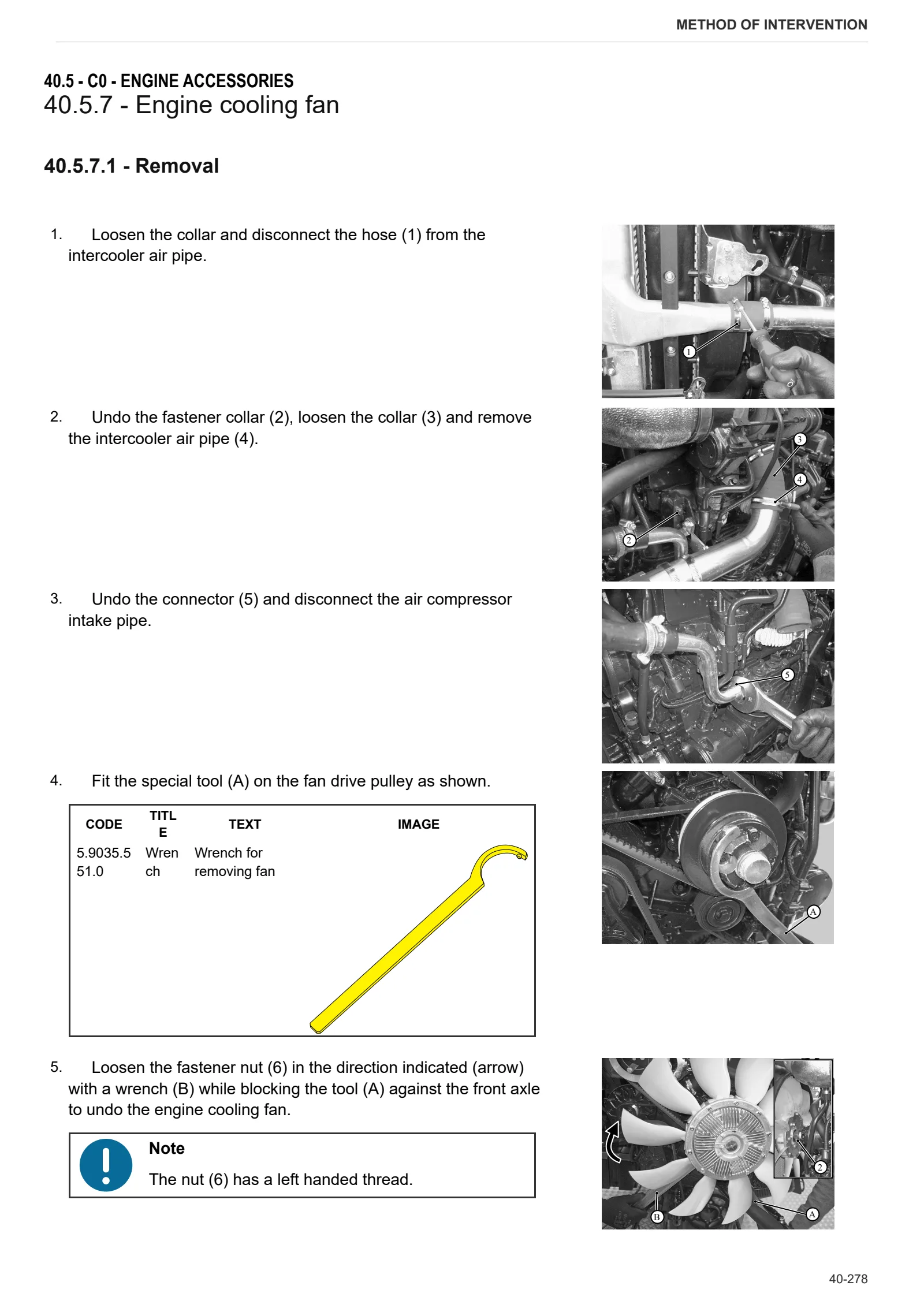
- Engine cooling fan
- Fuel tank
- Catalytic silencer
- Expansion tank
- Air filter container
- Oil measuring device
- Blower fan
- Protective cap (connector guides – glow plugs)
- Protective cap (relay)
- Fuel prefilter
- Fuel filter
- Fuel line
- Fuel delivery pump
- Removing and fitting the fuel pipes (injector, rail, high pressure pump)
- Disassembling and assembling the exhaust manifold
- Removal and refitting of the exhaust manifold
- Inlet module (5.66″ axial system)
- Inlet module (5.66″ axial system)
- Assembly sequence (Diesel Oxidation Catalyst, 5.66″ x 7″)
- Mount (module size 5.66″)
- V-Band clamp
- VBand clamp (3″ exhaust pipe)
- Removal and refitting of the glowplugs
- Disassembly and assembly of the starter
- Disassembly and assembly of the starter
- Alternator
- Alternator
- Alternator
- Removing and fitting the alternator (retainer bracket)
- Camshaft speed sensor
- Crankshaft speed sensor
- Removing and fitting the supply air pressure/temperature sender
- Mount fasteners (starter motor relay)
- Relay, mount (thermo-starter)
- Check the seal of the cooling system
D0 – Transmission
- Changing the transmission oil
- Sealants application
- Separating front gearbox housing from rear gearbox housing
- Separating centre gearbox housing from the rear axle
- INPUT clutch disc replacement
- INPUT unit
- INPUT unit disassembly
- Front gearbox casing cover
- Hydrostatic unit
- Hydrostatic unit pipes
- Clutch housing (with INPUT unit and hydrostatic unit) (1/2)
- Clutch housing (with INPUT unit and hydrostatic unit) (2/2)
- Front section of dual traction shaft (in clutch housing)
- Disassembling the front section of the dual traction shaft
- Replacing the variator input shaft bearings
- Replacing the WORK and TRANSPORT clutch assemblies (with the intermediate casing installed)
- Variator unit input gear assembly
- Disassembling the variator input gear unit
- Variable ratio transmission unit
- WORK and TRANSPORT clutch-planetary reduction gearbox assembly
- Planetary reduction gearbox for the WORK and TRANSPORT clutches
- Disassembling the WORK and TRANSPORT planetary reduction gearbox
- Disassembling the WORK and TRANSPORT clutches
- REVERSE clutch-planetary reduction unit
- Disassembling the REVERSE planetary reduction unit
- Pump unit flange
- Disassembling the pump support flange
- Speed range gear shafts
- Disassembling the range gear control lever
- Disassembling the transfer case gear
- PTO engagement clutch
- Disassembling PTO engagement clutch
- PTO casing
- Disassembling the PTO casing
- PTO drive shaft
- PTO speed selection lever
- PTO driven shaft
- Disassembling the PTO driven shaft
- Differential pinion
- Disassembling the differential pinion
- Disassembling the HD (Heavy Duty) range gear
- Dual traction output shaft
- Dual traction output shaft transfer idler gear
- Disassembling the dual traction output shaft
- Dual traction clutch
- Centre section of dual traction shaft (in variable transmission unit)
- Disassembling the centre section of the dual traction shaft
- Disassembling the dual traction clutch
E0 – Rear axle
- Axle casing
- Wheel mount disassembly
- Park brake unit
- Disassembling the park brake unit
- Rear differential
- Disassembling the rear differential case
- Removing rear differential
- Controlling and adjusting the clearance of the teeth on the pinion and the differential crown wheel
F0 – Front axle
- Separating front axle carrier from engine
- Dual traction shaft (DT)
- Front axle 4WD
- Adjusting the front axle end float
- Suspended axle pivot bracket
- Steering cylinders
- Removing steering cylinders
- Steering knuckle housing and half-shaft
- Front brake discs
- Adjustment of steering knuckle housing and axle shaft
- Pinion-differential assembly
- Planetary reduction gearbox
- Disassembly of the final drive unit
- Disassembly of the differential locking device
- Disassembling the differential assembly – pinion
- Pinion positioning and preload adjustment
- Adjusting differential preload and pinion-crown wheel backlash
- Disassembly of the differential
- Steering sensor actuator plate orientation
G0 – Bodywork – Cab – Platform
- Empty and charge the air conditioning system
- A/C system – Version with standard roof
- Air conditioning system controls – High-visibility roof system
- Air conditioning compressor
- Condenser
- Disassembling the condenser
- Dehydrator filter
- A/C unit
- Front mudguards
- Engine hood
- Engine hood mount
- Battery mount
- Cab access steps
- Cab
- Steering wheel
- Steering column
- Instrument cluster
- Front cab trim
- Driver seat
- Cab mat
- Control console and right hand side cab trim
- Left hand side cab trim
- Headliner trim
- Brake master cylinders
- Adjustment of Bowden cable
H0 – Hydraulic system
- Assembly Standard for bleeding brakes (brake Booster pumps)
- Services solenoid valve assembly
- Supplementary pump
- TANDEM pump
- Power steering pump
- Transfer pump
- Power steering
- Spool valves
- Rear ancillary utility distributor
- Front axle suspension valve block
- Trailer air braking valve
- Trailer air braking system operating control – Export D Version
- Air tanks
L0 – Electrical system
- 0440 9682 – Equipment harness
- 0440 9656 – Power harness
- Pressure sensor (L3)
- Pressure transducer (L3)
- Engine control unit
- A/C system ECU
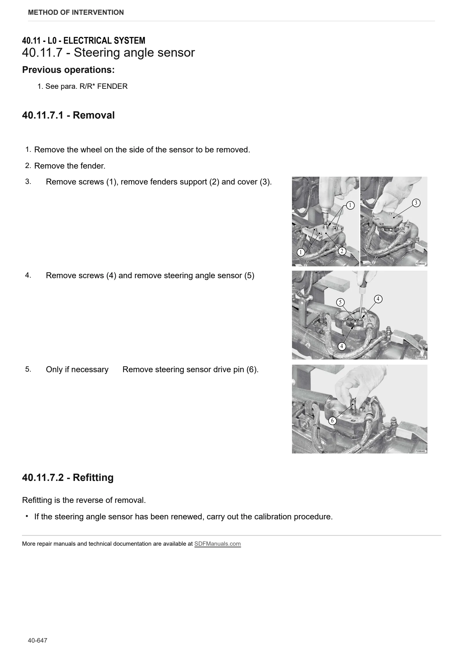
- Steering angle sensor
- Instrument cluster
- Tightening torques for nuts and bolts of electrical connections
- Multifunction armrest
M0 – Front PTO
- Front PTO
- Disassembling front PTO
- Disassembling the front PTO clutch-brake assembly
- Clutch pack end float values check
R0 – Rear lift
- Stabiliser tie-rod carrier
- S.A.C. – Automatic control station
- Disassembling the lift assembly (SAC)
- Bushes
- Auxiliary lift cylinders
- 3-point linkage
S0 – Wheels
- Rear wheels
- Front Wheels
V0 – Ballast – towing hitches
- Tightening Torques for Tow Hitches
- Standard fastener hardware: Tightening torque/Tension forces
- Tow hook sled
Wiring diagrams
Introduction
- Introduction
- Basic electronics for mechanics (1/2)
- Basic electronics for mechanics (2/2)
- Electrical and electronic components (1/2)
- Electrical and electronic components (2/2)
Components
- A – Starting and charging
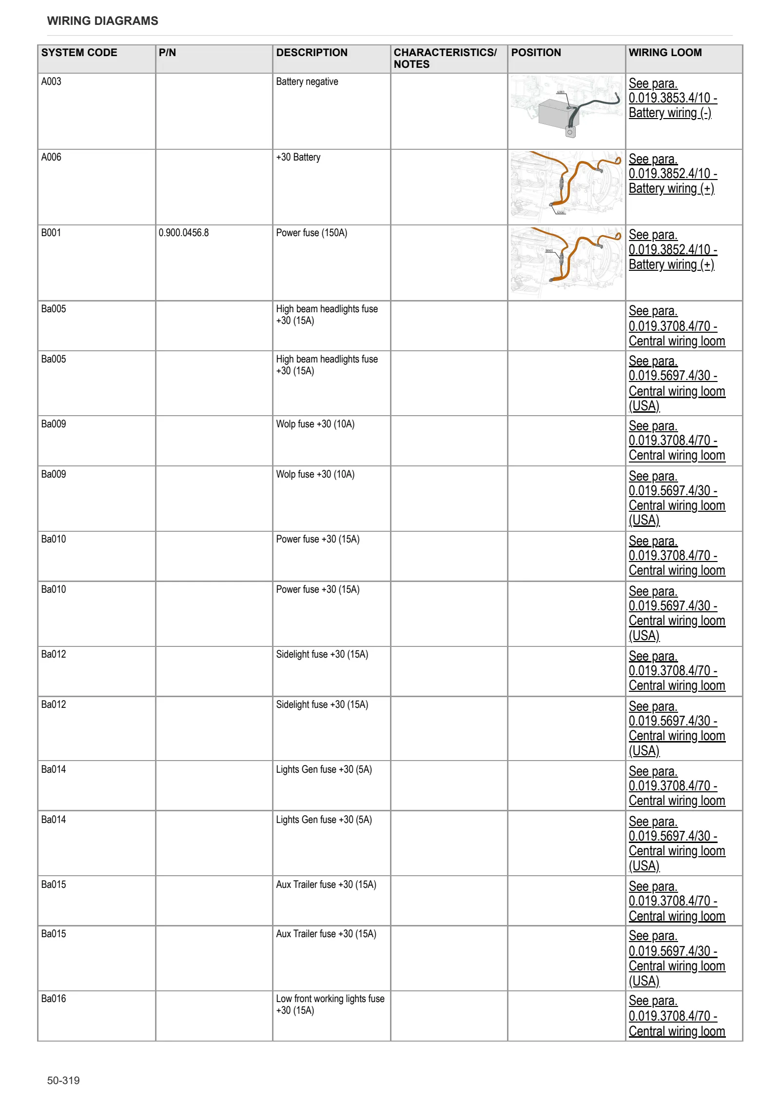
- B – Fuses
- C – Grounds
- D – Intermediate connections
- E – On-board instruments and visual and audible indicators
- F – External lights (rotating beacon)
- G – Interior lights
- H – Manual electrical controls (steering column stalk)
- I – Circuit breakers
- J – Relays
- K – Sensors and transmitters
- L – Electromagnets and solenoid valves
- M – Electrical/electronic devices, Flasher units and Timers
- N – Electric motors and actuators
- O – Resistors and rheostats
- P – Various services
- R – Diagnostics
Systems
- S001 – Electronic engine governor with USA flasher relay
- S001 – Electronic engine throttle
- S002 – Preheating
- S002 – Pre-heat with USA flasher relay
- S003 – Starter
- S004 – Lift
- S005 – Lights
- S005 – Lights with USA flasher relay
- S006 – work lights – version with 4 lights
- S007 – work lights – version with 8 lights
- S008 – Windscreen wiper
- S009 – Instrument panel
- S009 – Instrument cluster with USA flasher relay
- S010 – Wolp Display
- S011 – Audio system – i-Monitor
- S012 – Manual air conditioner
- S013 – Automatic air conditioning
- S014 – Transmission with mechanical engagement distributors
- S014 – Transmission with electronic action distributors
- S015 – PTO
- S016 – Accessories
- S017 – Can Bus
- S017 – Can Bus USA
- S018 – Can Bus – distributors line
- S019 – Can Bus – engine line
- S020 – Brakes
- S020 – Brakes with USA flasher relay
- S022 – Diagnostics with manual climate control
- S022 – Diagnostics with manual climate control and USA flasher relay
- S023 – Diagnostics with automatic climate control
- S023 – Diagnostics with automatic climate control and USA flasher relay
- S024 – Distributors with mechanical action
- S025 – Distributors with electrical action
- S026 – ISO 11783 line
- S026 – ISO 11783 line USA
- S027 – Front axle suspension with mechanical action distributors
- S028 – Front axle suspension with electric action distributors
- S029 – Hydraulic Engine Brake
- S030 – Front loader – Version with electrohydraulic distributors
- S031 – Front loader – Version with mechanically controlled distributors
- S032 – Rapid steer system (SDD)
Wiring harnesses
- 0.011.3797.3 – SBA-ASM
- 0.011.3824.4/10 – Rotating beacon
- 0.012.2756.3 – Front PTO solenoid valve
- 0.014.0002.4 – Supplementary arm work lights – Version with front lift
- 0.014.1567.4/20 – Front windscreen wiper
- 0.014.1645.4/10 – ITA-D Air braking pressure switch
- 0.014.8453.4 – Front wiper motor – fixed windscreen version
- 0.015.9043.4/50 – Transmission solenoid valves
- 0.016.1001.4/20 – Hydraulic trailer braking valve
- 0.017.0496.4/10 – Low-mounted front work lights
- 0.017.9311.4/40 – Front loader – Version with mechanically controlled distributors
- 0.019.2889.4 – Rear distributors
- 0.019.2960.4/30 – Rear wiring loom
- 0.019.3018.4/40 – Front wiring loom
- 0.019.3708.4/70 – Central wiring loom
- 0.019.3711.4/10 – Right hand transmission with mechanical action distributors
- 0.019.3732.4/20 – Rear mudguards
- 0.019.3852.4/10 – Battery wiring (+)
- 0.019.3853.4/10 – Battery wiring (-)
- 0.019.4043.4/20 – Transmission display
- 0.019.4068.4/10 – Instrument cluster
- 0.019.4175.4/10 – Cab front lights
- 0.019.4379.4/10 – Cab under roof
- 0.019.5694.4/20 – Cab roof with automatic climate control
- 0.019.5695.4/20 – Cab roof work lights
- 0.019.5696.4/10 – Front lights on cab (EU)
- 0.019.5697.4/30 – Central wiring loom (USA)
- 0.019.5698.4/10 – Rear mudguards
- 0.019.5700.4/40 – Front suspension
- 0.019.5702.4/10 – ISO 11786
- 0.019.5777.4 – Front axle suspension solenoid valve
- 0.019.6012.4 – work lights
- 0.019.6013.4 – Cab roof work lights
- 0.019.6516.4-Multifunction armrest
- 0.019.8827.4 – Rapid steer system (SDD)
- 0.019.8844.4 – Roof
- 0.019.9059.4/10 – ISO 11783 – Cab line
- 0.019.9513.4/10 – Right hand transmission with electrical action distributors
- 0.019.9586.4 – ISO 11783 – Rear line
- 0.019.9652.4/10 – Agrosky VG
- 0.019.9653.4/10 – Agrosky AS
- 0.019.9803.4 – Front lights and horn
- 0.020.0726.4 – Fuel pre-filter
- 0.020.0963.4 – Front lights and horn
- 0.020.4303.4 – Front lights on cab (USA)
- 0.020.5903.4 – Hydraulic trailer braking (ITA)
- 0.021.1915.4/10 – Relay and switches for front loader
- 0.021.1916.4 – Front loader
Service Info
A0 – TRACTOR
- Diagnostics 2026 subscription
- After-sales 2026 subscription
- SERVICE NEWS RESEARCH GUIDE
- Diagnostics 2025 subscription
- After-sales 2025 subscription
- Diagnostics 2023 subscription
- Diagnostics 2024 subscription
- Diagnostics 2022 subscription
- Diagnostics 2021 subscription
- After-sales 2024 subscription
- After-sales 2023 subscription
- After-sales 2022 subscription
- After-sales 2021 subscription
- After-sales 2019 subscription
- SDF Parts and SDF Service DVV 04/2014, version 26
- New function: Download PDF manuals
- Diagnostics – 2020 subscription
- After-sales – 2020 subscription
- After-sales – 2018 subscription
- Service and Spare Parts – 2017 Subscription
- SDF Parts and SDF Service DVDs 05/2014 version 25
- SDF Parts and SDF Service DVDs 03/2013 version 24
B0 – ENGINE
- Flushing the lubrication circuit
- Engine pulley detachment
- Deutz AG engine oil specifications
- SerDia 2010 updating license file
C0 – ENGINE ACCESSORIES
- Diagnostic protocol – AdBlue – Float level unit
- Filter and prefilter tool p/n 5.9035.865.0
- e-Visco fan blades come in contact with the duct
D0 – TRANSMISSION
- PTO collar breakage
- T57 Alarm – Transmission problems
F0 – FRONT AXLE
- Check the front axle steering knuckles for wear
- Steering behavior check procedure
- Operator’s Manual Update
G0 – BODYWORK – CAB
- Air conditioning with error U90
- Air conditioning system recharging
- Mechanical cab suspension brackets
H0 – HYDRAULIC AND PNEUMATIC SYSTEM|
- Hydraulic CUNA trailer braking kit (ITALY)
- Single connection hydraulic braking kit availability update – only for EUROPEAN market
- PNEUMATIC TRAILER BRAKE CYLINDER
- Brake booster pump oil leakage
- SDD steering unit position sensor and solenoid valve replacement
- L0 – ELECTRIC AL SYSTEM