Document overview
Workshop Manual PDF for HURLIMANN XB 105 TB → ZKDCS40200TH10001, XB T-TB (STAGE 3A) family. Document language: English; 1,173 pages.
The corresponding English table of contents contains 50 sections and 396 individual topics.
Main sections included
- Introduction
- Safety
- Technical characteristics
- Calibrations and electronic diagnosis
- Method of intervention
- Wiring diagrams
- Service Info
Document details
- Brand: HURLIMANN
- Family: XB T-TB (STAGE 3A)
- Model: XB 105 TB
- Starting serial number: ZKDCS40200TH10001
- Document type: Workshop Manual
- Language: English
- Pages: 1,173
- File size: 316.71 MiB
- Format: Digital PDF download
Compatibility
Before purchasing, verify that your machine model and reference code match HURLIMANN XB 105 TB → ZKDCS40200TH10001.
Complete table of contents
Introduction
- Introduction – Engines
- Tightening torques
- Identification of the engine type and serial number position, Europe version
- Identification of the engine type and serial number position, EPA version
- Identification of the injection pump type
- Identification of the injector type
- Injector type identification
- Units of measurement and conversion factors
Safety
Preface
- Important notes concerning safety
Important safety information
- Recognising hazards
- Indications for persons in contact with the tractor
Safety rules
- Risks during tractor preparation
- Risks during maintenance
- Work on machine systems
- Special disassembly/assembly/inspection procedures
Safety pictograms
- Replacing safety pictograms
Environmental risks
- Hazards associated with the operating environment
Technical characteristics
Engine
- Engine block technical data
- Crankshaft technical data
- Technical data for pistons – Piston rings
- Connecting rod technical data
- Camshaft technical data – static advance of 12°
- Timing gears technical data
- Counter-rotating weights technical data
- Technical data and dimensions of valves – valve springs
- Technical data and dimensions of cylinder heads – valve guide – valve seats
- Technical data and dimensions of rocker arms – rocker shafts – tappets
- Engine injectors technical data
- Hydraulic tappets diagram
Transmission
- Transmission
- Four-wheel drive electrohydraulical engagement and parking brake assembly
- Hydraulic reverse power shuttle
- HI-LO unit
- Rear PTO
- Views of transmission
Rear axle
- Rear differential
- Rear axle
Front axle
- Front axle 4 WD
Hydraulic system
- Braking system
- Separate-Brakes valve
- Trailer braking valve
- Power steering 125 cc
- Transfer pump
- Ancillary oil pump
- Power steering pump
- Suction pump filter
- Delivery line filter
- Distributor unit
- Pressure regulator valve unit
- Service valve unit
- Reverse shuttle control valve block
- Rear PTO
- Transmission hydraulic circuits
- Hydraulic distributor circuit
Rear lift
- Mechanical rear lift
Calibrations and electronic diagnosis
Diagnostic tools
SDF Analyser
- SDF Analyser
- SDF Analyser – Diagnostic socket
Diagnostic tool screens
- ECU interrogation
- PC Tester Screens – Smart Lever – Purpose of this document
- PC Tester Screens – Smart Lever – Home Menu
- PC Tester Screens – Smart Lever – Main Menu
- PC Tester Screens – Smart Lever – Monitor Menu
- PC Tester Screens – Smart Lever – Parameters Menu
- PC Tester Screens – Smart Lever – Calibration Menu
- PC Tester Screens – Smart Lever – Test Menu
- PC Tester Screens – Smart Lever – Alarms Menu
- PC Tester Screens – Engine ECU – Structure
Commissioning and calibrating the tractor
- Digital Instrument Calibration
- Wheel constants
- MIS – Document purpose
- Commissioning – Instruments and information required
- MIS – Procedure description
- Commissioning – Eeprom re-initialisation
- Commissioning – Basic procedure
- MIS – Tractor configuration
- Commissioning – Calibration of the shuttle clutches
- Commissioning – Calibrating Stop&Go function
- Calibr. Hydraulic reverse shuttle – Purpose of this document
- Reverse shuttle calibration – Clutch calibration
- Reverse shuttle calibration – Stop&Go calibration
- Reverse shuttle calibration – Instruments and information required for calibration
- Shuttle calibration – Clutch calibration procedure
- Reverse shuttle calibration – Stop&Go calibration procedure
- Commissioning – Engine ECU – Presentation screen
- Commissioning – Engine ECU – Preheating menu
- Commissioning – Engine ECU – Alarms List
- Commissioning – Engine ECU – Structure
- Commissioning – Engine ECU – Main menu
- Commissioning – Engine ECU – Configuration
- Commissioning – Engine ECU – Engine menu
- Commissioning – Engine ECU – HML menu
- Commissioning – Engine ECU – Alarms Menu
- Commissioning – Engine ECU – Wheel Calibration Menu
- Commissioning – Engine ECU – Wheels menu
- Commissioning – Engine ECU – HRT Menu
- Commissioning – Engine ECU – DERATING Menu
- Commissioning – Engine ECU – Engine type config.
- Commissioning – Engine ECU – Engine type config.
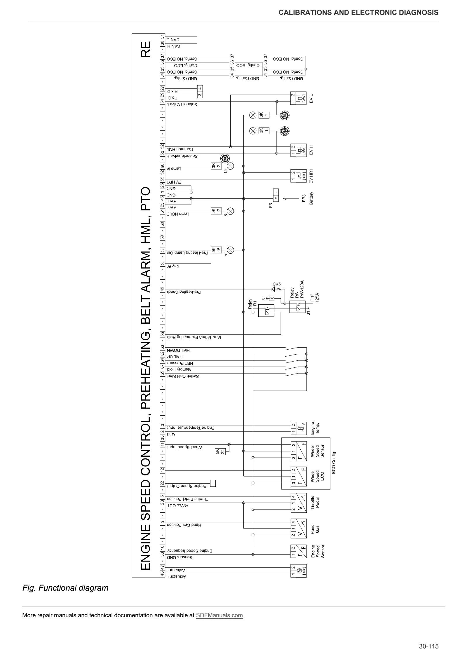
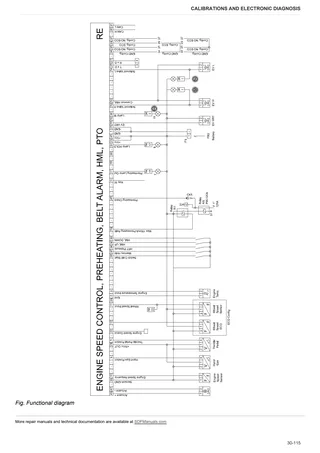
- Commissioning – Engine ECU – Functional diagram
ECU alarms
- ECU alarms
Engine alarms
- Alarms – SLH engine alarm code list – Version with hydraulic reverse shuttle
Transmission alarms
- Alarms – Transmission alarms list
Instrument panel alarms
- Alarms – Instrument cluster alarms list
- Auto-diagnostics of the PTO indicator lamp
Method of intervention
- Workshop tools for disassembly and reassembly
B0 – Engine
- Separating engine from transmission
- Engine flywheel
- ENGINE
- Ancillary services belt
- Preliminary disassembly operations
- Checking engine block
- Crankshaft
- Crankshaft checks
- Flywheel checks
- Renewal of crankshaft rear oil seal
- Pistons and cylinder liners
- Pistons and rings check
- Cylinder liners check
- Check connecting rods – gudgeon pins – rod cap screws
- Camshaft checks
- Camshaft
- Valve timing
- Timing gear checks
- Adjusting timing gears backlash
- Counter-rotating weights
- Counter-rotating weight checks
- Overhaul of counter-rotating weights assembly
- Valves check
- Valve seats check
- Valves sealing check
- Adjusting valve clearance
- Valve guides check and replacement
- Inspecting the rocker arms and rocker shafts
- Cylinder heads
- Determining correct head gasket thickness
- Valve springs check
- Heat exchanger removal
- Lubrication pump
- Lubrication pump disassembly
- Oil sump
- INJECTION PUMPS, GOVERNOR AND FUEL SUPPLY
- Synchronising injection pumps
- Injectors assembly
- Checking injectors protrusion – Renewal of copper bushes
- Injectors check
- Injection pump control rod
- Overhaul of the mechanical governor (standard and with LDA valve)
- Electronic governor adjustment
- Installation of electronic governor support
- Engine coolant pump
- Engine coolant pump
- Thermostatic valve
- Checking the thermostat valve
- Cooling and intake ducts
- Final engine checks
- Final refitting operations
- Pulley hub fixing (for types without front PTO)
- Pulley hub fixing (for types with front PTO)
C0 – Engine accessories
- Transmission oil radiator and intercooler
- Exhaust pipe
- Exhaust silencer
- Engine coolant radiator
- Fuel tank
- Engine cooling fan
- Air filter container
- Radiator assembly
- Expansion tank
- Engine coolant replacement
D0 – Transmission
- Changing the transmission oil
- Engine torsional spring plate
- Shuttle unit – Complete assembly
- Disassembling the shuttle unit
- Removing the forward drive clutch unit
- Disassembling the reverse drive clutch unit
- Input shaft assembly and tone wheel
- DT shaft in transmission
- Clutch housing – separation from transmission
- Range selector assembly
- Disassembling the range selector assembly
- Gearbox internal cover
- HI-LO unit
- Disassembling the HI range clutch housing
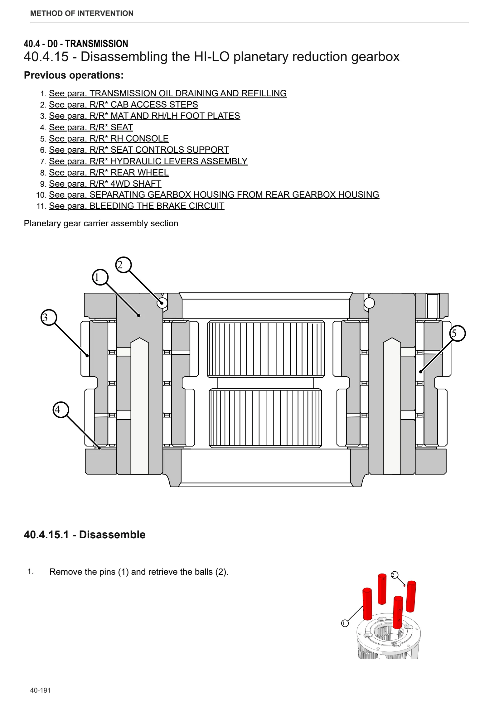
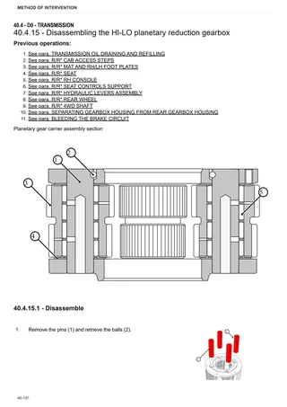
- Disassembling the HI-LO planetary reduction gearbox
- Gearbox and HI-LO unit
- Secondary shaft – Version with HI-LO
- Primary shaft
- Disassembling the gearbox input shaft
- Disassembly of secondary shaft – Version with HI-LO
- Disassembly of the main shaft
- Disassembly of HI-LO unit output shaft
- PTO output shaft 2 speed version
- PTO output shaft – 4 speed version
- Disassembling the PTO output shaft 2 speed version
- Removing the PTO output shaft – 4 speed version
- PTO engagement clutch
- Disassembling PTO engagement clutch
- Pump drive PTO – External gear
- Pump drive PTO – Internal gear
- Disassembling the PTO output flange shaft – 2 speed version
- Disassembling PTO final flange shaft – 4 speed version
- Disassembling the ground speed PTO output shaft
- Disassembling the ground speed PTO clutch engage mechanism
- Removing the rear pinion – 2-range version
- Removing the rear pinion – 4-range version
- Adjustment of the differential – Bevel gear set
- Removing dual traction output shaft 2-range version
- Removing dual traction output shaft – 4-range version
- Parking brake disc sectors – Versions with hydraulically engaged four wheel drive
- Parking brake disc sectors
- Disassembly of dual traction clutch – Easyshift with mechanical park brake
E0 – Rear axle
- RH wheel mount
- LH wheel mount
- Removing right/left hand rear axle
- LH brake carrier
- RH brake carrier
- Disassembly of the brake carrier
- Rear differential
- Removing rear differential
F0 – Front axle
- 4WD shaft
- Separating front carrier from engine
- Front axle (4WD)
- Steering cylinders
- Removing steering cylinders
- Differential assembly
- Disassembling the differential assembly
- Bevel gear set
- Disassembly of the differential
- Adjustment of the bevel gear set
- Differential assembly adjustment
- Front axle adjusting endfloat
- Planetary reduction gearbox
- Disassembly of the planetary reduction gearbox
- Steering knuckle housing and half-shaft
- Adjustment of steering knuckle housing and axle shaft
- Front brake discs
- Front axle brake piston
G0 – Bodywork – Cab – Platform
- Roll bar
- Mat and footboards
- Engine cowl
- Engine hood mount
- Cowl frame
- Battery mount
- Driver access steps
- Right hand console
- Lift control levers
- Rear mudguard
- Seat
- Seat mounting plate
- Steering wheel
- Instrument cluster
- Steering column
- Front mudguards
- Brake master cylinder
H0 – Hydraulic system
- Lift and ancillary utility distributor circuit pump.
- Power steering pump
- Transmission oil transfer pump
- Power steering
- Rear ancillary distributor
- Ancillary solenoid valve block
- Disassembling the ancillary solenoid valve block
- Shuttle solenoid valves assembly
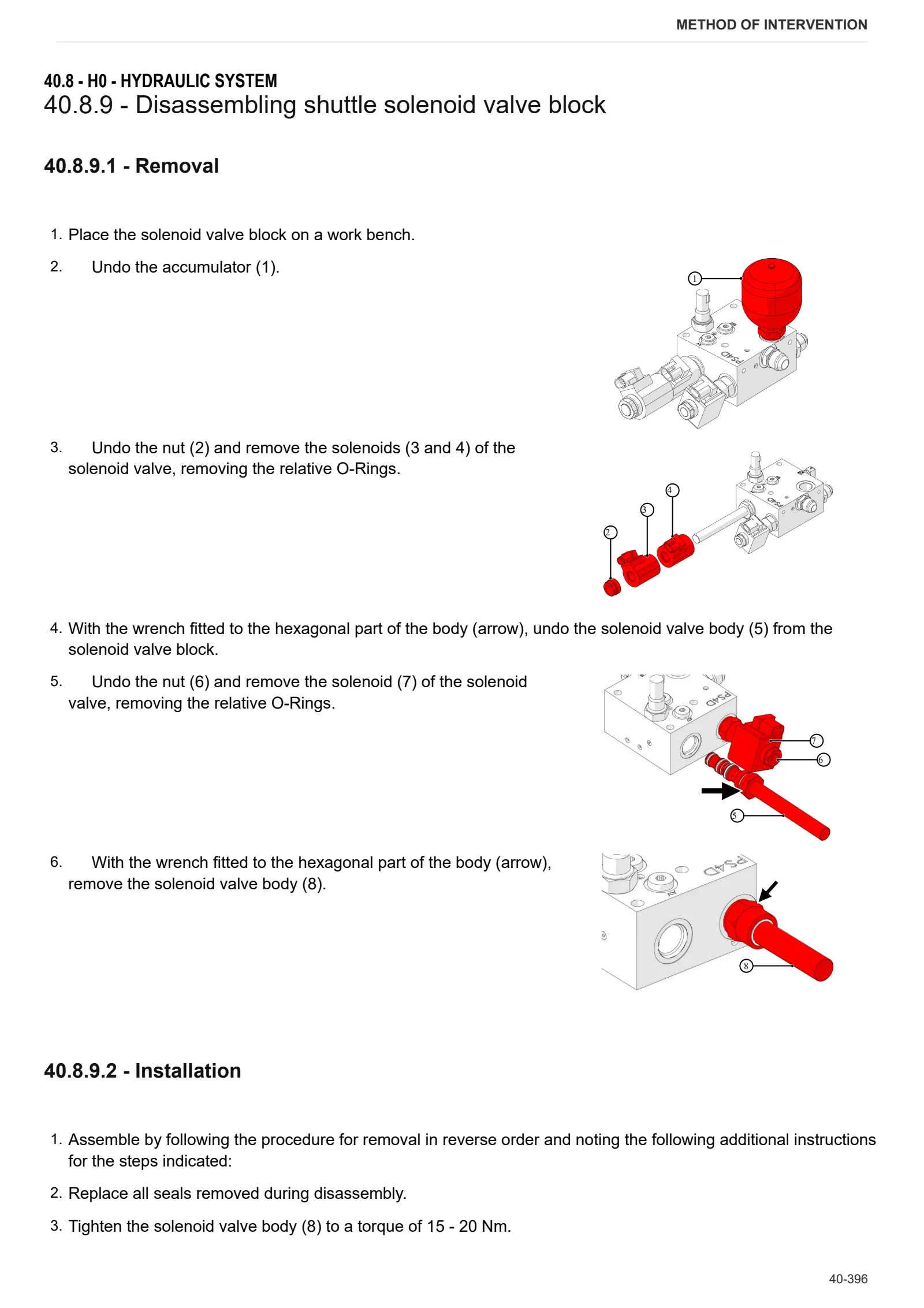
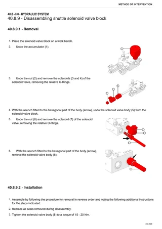
- Disassembling shuttle solenoid valve block
- Trailer hydraulic braking valve
- Bleeding the braking circuit
L0 – Electrical system
- Engine control unit
- Throttle pedal potentiometer
- Hydraulic reverse shuttle output speed sensor
- Instrument cluster
- Battery master switch
- Steering column stalk
- Reverse shuttle control unit and drive direction selector
R0 – Rear lift
- S.A.C. Automatic control station
- SAC disassembly – Automatic control station (mechanical distributor)
- Rear lift cylinder
- Connecting the Bowden cable to the position and draft control lever (mechanical lift)
- Adjusting mechanical rear lift controls
- Checking and testing the mechanical rear lift
- Rear lift draft rod replacement
- 3-point linkage
S0 – Wheels
- Rear wheel
- Front wheel
V0 – Ballast – towing hitches
- Tow hook sled
V1 – AFTERMARKET KITS
- 9.Y3654.90.0 and 9.Y4054.90.0 kit installation
Wiring diagrams
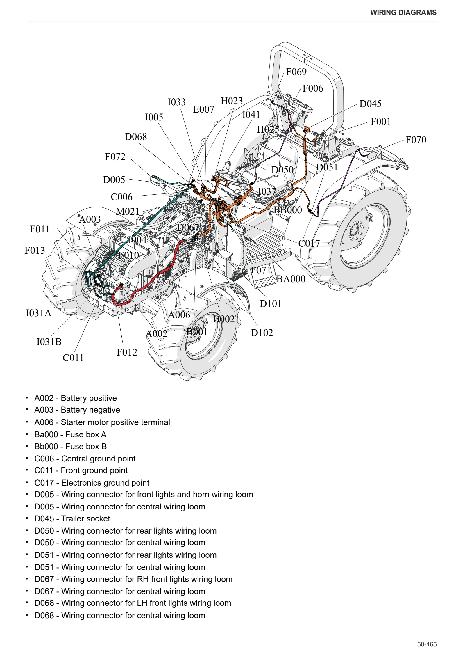
- Functional diagram
Introduction
- Introduction
- Basic electronics for mechanics (1/2)
- Basic electronics for mechanics (2/2)
- Electrical and electronic components (1/2)
- Electrical and electronic components (2/2)
Components
- Locations of main control units – Version with mechanical reverse shuttle
- Locations of main control units – Version with hydraulic reverse shuttle
- 2.8519.174.0 – Engine ECU
- 0.016.3802.4/40 – Hydraulic reverse shuttle lever
- 2.8339.285.0/50 – Digital Instrument (Cluster) – Version with hydraulic reverse shuttle
- 2.8339.285.0/50 – Digital Instrument (Cluster) – Version with mechanical reverse shuttle
- 2.8519.114.0 – Rear PTO ECU
- A – Starting and charging systems – Version with hydraulic reverse shuttle
- A – Starting and charging systems – Version with mechanical reverse shuttle
- B – Valve unit, Fuses – Version with hydraulic reverse shuttle
- B – Valve unit, Fuses – Version with mechanical reverse shuttle
- C – Ground points – Version with hydraulic reverse shuttle
- C – Ground points – Version with mechanical reverse shuttle
- D – Intermediate junction connectors – Version with hydraulic reverse shuttle
- D – Intermediate junction connectors – Version with mechanical reverse shuttle
- E – On-board instruments and visual and audible indicators – Version with hydraulic reverse shuttle
- E – On-board instruments and visual and audible indicators – Version with mechanical reverse shuttle
- F – External lights – Deutz Fahr, Lamborghini, Hürlimann version
- F – External lights – Same version
- H – Manual electrical controls (steering column switch) – Version with hydraulic reverse shuttle
- H – Manual electrical controls (steering column switch) – Version with mechanical reverse shuttle
- I – Switches – Version with hydraulic reverse shuttle
- I – Switches – Version with mechanical reverse shuttle
- J – Relays – Version with hydraulic reverse shuttle
- J – Relays – Version with mechanical reverse shuttle
- K – Sensors and transmitters – Version with hydraulic reverse shuttle
- K – Sensors and transmitters – Version with mechanical reverse shuttle
- L – Electromagnets and solenoid valves – Version with hydraulic reverse shuttle
- L – Electromagnets and solenoid valves – Version with mechanical reverse shuttle
- M – Electric and electronic devices, intermittent units and timers – Version with hydraulic reverse shuttle
- M – Electric and electronic devices, intermittent units and timers – Version with mechanical reverse shuttle
- N – Electric motors and actuators – Version with hydraulic reverse shuttle
- N – Electric motors and actuators – Version with mechanical reverse shuttle
- O – Resistors and rheostats – Version with hydraulic reverse shuttle
- O – Resistors and rheostats – Version with mechanical reverse shuttle
- P – Other ancillaries – Version with hydraulic reverse shuttle
- P – Other ancillaries – Version with mechanical reverse shuttle
- R – Diagnosis – Version with hydraulic reverse shuttle
- R – Diagnosis – Version with mechanical reverse shuttle
Systems
- Schematic diagram – Version with hydraulic reverse shuttle
- Schematic diagram – Version with mechanical reverse shuttle
- S001 – Electronic engine throttle
- S002 – Preheating
- S003 – Starting system – Version with hydraulic reverse shuttle
- S003 – Starting system – Version with mechanical reverse shuttle
- S004 – Lights (Deutz Fahr, Lamborghini, Hürlimann) – Version with hydraulic reverse shuttle
- S004 – Lights (Deutz Fahr, Lamborghini, Hürlimann) – Version with mechanical reverse shuttle
- S004 – Lights (Same) – Version with hydraulic reverse shuttle
- S004 – Lights (Same) – Version with mechanical reverse shuttle
- S005 – Instrument cluster – Version with hydraulic reverse shuttle
- S005 – Instrument cluster – Version with mechanical reverse shuttle
- S006 – Transmission – Version with hydraulic reverse shuttle
- S006 – Transmission – Version with mechanical reverse shuttle
- S007 – PTO
- S007 – PTO (540-750)
- S007 – PTO (four speeds)
- S008 – Accessories – Version with hydraulic reverse shuttle
- S008 – Accessories – Version with mechanical reverse shuttle
- S009 – CAN Bus – Version with hydraulic reverse shuttle
- S009 – CAN Bus – Version with mechanical reverse shuttle
Wiring harnesses
- 0.010.9057.3 – Front lights
- 0.014.1645.4/10 – Trailer brake
- 0.014.9195.4/20 – Preheating
- 0.015.1440 – 100 HP shuttle SV
- 0.015.7309.4 – Front lights and horn – Deutz Fahr, Lamborghini, Hürlimann version
- 0.015.7310.4 – Front lights and horn – Same version
- 0.017.0474.4 – Battery positive terminal
- 0.017.1192.4/10 – Rear lights
- 0.017.5672.4 – PTO 540 – 1000 wiring loom
- 0.018.2292.4 – Tappets
- 0.019.7047.4 – Preheat and power feed
- 0.020.7758.4 – Battery cut-off
- 0.021.4505.4 – PTO 540 – 750
- 0.021.9320.4/10 – Central – Version with mechanical reverse shuttle
- 0.021.9321.4/10 – Central – Version with hydraulic reverse shuttle
- 0.021.9324.4 – Engine
- 0.021.9326.4/10 – Battery wiring (-)
Service Info
A0 – TRACTOR
- Diagnostics 2026 subscription
- After-sales 2026 subscription
- SERVICE NEWS RESEARCH GUIDE
- Diagnostics 2025 subscription
- After-sales 2025 subscription
- Diagnostics 2023 subscription
- Diagnostics 2024 subscription
- Diagnostics 2022 subscription
- Diagnostics 2021 subscription
- After-sales 2024 subscription
- After-sales 2023 subscription
- After-sales 2022 subscription
- After-sales 2021 subscription
- After-sales 2019 subscription
- SDF Parts and SDF Service DVV 04/2014, version 26
- Diagnostics – 2020 subscription
- After-sales – 2020 subscription
- After-sales – 2018 subscription
- Service and Spare Parts – 2017 Subscription
B0 – ENGINE
- Flushing the lubrication circuit
- Deutz AG engine oil specifications
C0 – ENGINE ACCESSORIES
- Diagnostic protocol – AdBlue – Float level unit
- Filter and prefilter tool p/n 5.9035.865.0
D0 – TRANSMISSION
- Hydraulic shuttle central disc
- Hand brake lever greasing
F0 – FRONT AXLE
- Check the front axle steering knuckles for wear
- Steering behavior check procedure
G0 – BODYWORK – CAB
- Air conditioning system recharging
H0 – HYDRAULIC AND PNEUMATIC SYSTEM|
- Hydraulic CUNA trailer braking kit (ITALY)
- Single connection hydraulic braking kit availability update – only for EUROPEAN market
- L0 – ELECTRIC AL SYSTEM