Document overview
Workshop Manual for DEUTZ FAHR C 9206 TS/TSB → 17000 from the C 9000 (STAGE 3B) family. Digital PDF in English with 909 pages.
The corresponding English table of contents contains 20 sections and 202 individual topics.
Main sections included
- Introduction
- General information
- Engine
- Engine accessories
- Pivot points
- Electrical equipment
- Threshing unit
- Cleaning unit
- Grain tank – Elevator
- Service Info
Document details
- Brand: DEUTZ FAHR
- Family: C 9000 (STAGE 3B)
- Model: C 9206 TS/TSB
- Starting serial number: 17000
- Document type: Workshop Manual
- Language: English
- Pages: 909
- File size: 106.88 MiB
- Format: Digital PDF download
Compatibility
Before purchasing, verify that your machine model and reference code match DEUTZ FAHR C 9206 TS/TSB → 17000.
Complete table of contents
Introduction
- Introduction
- Safety instructions – maintenance and repair
- General safety instructions
- Tightening Torques
General information
- Wheel rim to hub screws and nuts tightening torques
- Tightening torques for nuts and bolts of electrical connections
- Conversion tables
- Tightening values, screwing classes
- Lubricants
- Seal materials
- One-component adhesive
- Approved list of lubricating oil quality class – DEUTZ
- Securing bush support tightening values
- Maintenance and repair
- Care and maintenance
Engine
- Check the crankshaft bearings (L3)
- Removing and fitting the piston cooling nozzles
- Assembly and disassembly of the crankshaft (L3)
- Crankshaft check (L3)
- Check the endfloat of the crankshaft (L3)
- Assembly and disassembly of the connecting rod drum (L3)
- Disassembly and assembly of the control elements
- Removing and fitting the oil pickup pipe (fastener elements)
- Disassembly and completion of the pilot unit (L3)
- Connecting rod drum check (L3)
- Disassembly and assembly the cylinder head (fastening elements) (L3)
- Measuring piston protrusion (L3)
- Replacing the injector bush (L3)
- Replacing the injector bush (loose injector bush) (L3)
Engine accessories
- Installing flange joint
- Tightening torque of the screws of the supports – P/N 939401
- Pressure transducer (L3)
- Pressure sensor (L3)
- Temperature sender (L3)
- Temperature sender (L3)
- Temperature sender (L3)
- Technical data – Speed indicator
- NOx sensor (L3)
- NOx sensor (L3)
- Fuel tank thermal protection assembly
- Exhaust pipe thermal protection
- Add. fan bearing
Pivot points
- Installing rotation angle transducers – P/N 939036
- Installing telescopic tube – P/N 939431
Electrical equipment
Components
- A – Starting and charging
- 04216944 – Engine control unit
- 2.8519.074.0/20 – HLHP control unit
- 16050210 – CAN “DAVID” module A13
- 16057402 – CAN module A27
- B – Fuses
- C – Grounds
- D – Intermediate connections
- E – On-board instruments and visual and audible indicators
- F – External lights
- G – Interior lights
- H – Electrical and manual controls
- I – Circuit breakers
- J – Relays
- K – Sensors and transmitters
- L – Electromagnets and solenoid valves
- M – Electrical/electronic devices, flasher units and timers
- N – Electric motors and actuators
- O – Resistors, rheostats, diodes and diode boards
- P – Various services
- R – Diagnostics
- T – Power supply points (+15 o +30)
Systems
- S012 – Power supply (+15)
- S003 – Power supply (+30)
- S004 – Instrument panel
- S005 – Diagnostics – Accessories
- S006 – Sidelights
- S006A – High/low beam lights
- S006B – Turn signals
- S007 – Work lights
- S008 – Brakes
- S009 – Manual air conditioner
- S010 – Windscreen wipers
- S011 – Electronic engine management
- S012 – Starting
- S013 – Transmission
- S014 – Can Bus
- S015 – Pick-up reel
- S016 – Header float, lateral rotation and cutting angle without balance
- S016a – Header float, lateral rotation and cutting angle with balance
- S017 – Feed passage reverser
- S018 – Threshing unit
- S019 – Straw walker
- S020 – Sieves
- S021 – Straw chopper
- S022 – Spreader deflectors
- S023 – Grain tank
- S024 – Grain tank discharge pipe
- S025 – Lubrication system
- S026 – Rape cutter bar
- S027 – Balance
- S028 – AdBlue
WIRING HARNESSES
- 0.015.5464.4/10 – Starter motor
- 0.015.5466.4/10 – Header
- 0.016.1616.4 – Balance system main solenoid valve
- 0.016.6617.4/10 – Straw walker sensors
- 0.017.4579.4/10 – Electric motors
- 0.017.4582.4/30 – Engine interface
- 0.017.4990.4/10 – Solenoid valves block
- 0.017.5043.4/20 – Side instrument panel
- 0.017.6835.4 – Fuse box earth
- 0.017.5070.4/10 – LH license plate light
- 0.017.5070.4/10 – RH license plate light
- 0.017.5671.4 – Maintenance work lights
- 0.019.0691.4 – Pedal switch
- 0.019.0725.4/10 – Operator seat safety system
- 0.019.2373.4 – Front wiring loom
- 0.019.2374.4 – Tow hook camera
- 0.019.2375.4/10 – Balance controller
- 0.019.2376.4/10 – Cutting angle sensor
- 0.019.2377.4 – Roof
- 0.019.9850.4/10 – Grain tank
- 0.020.4444.4 – RH upper front work light
- 0.020.4444.4 – LH upper front work light
- 0.020.4444.4 – RH rear work light
- 0.020.4444.4 – LH rear work light
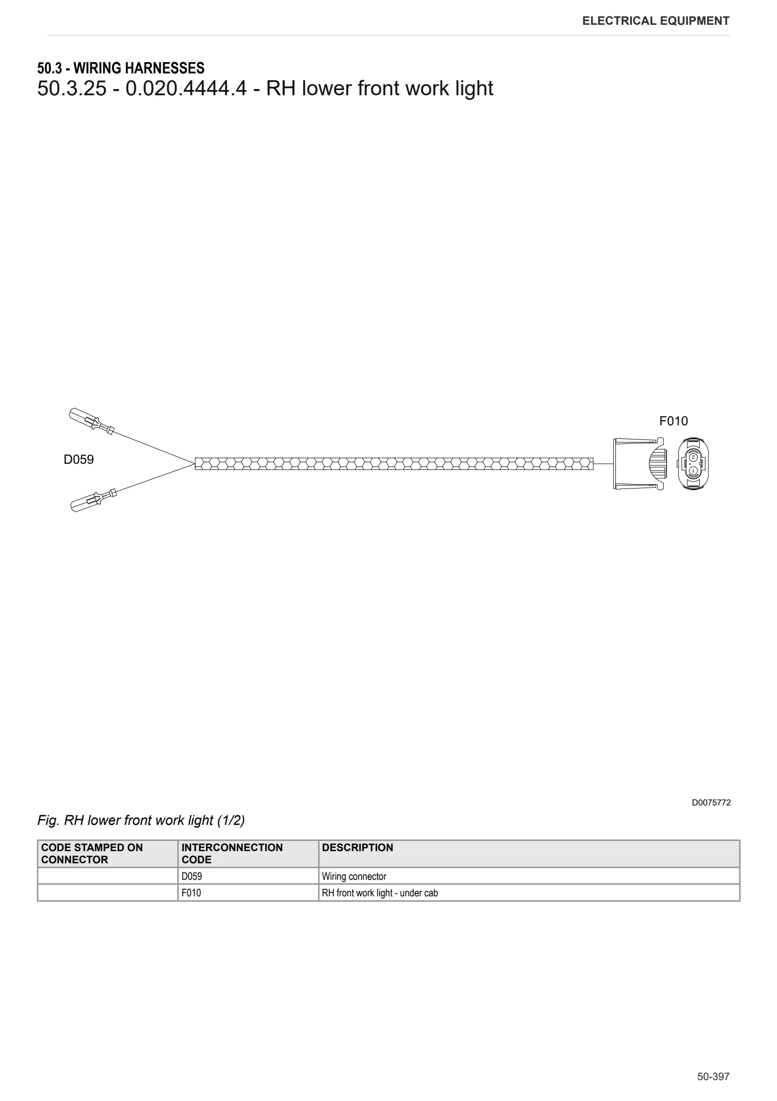
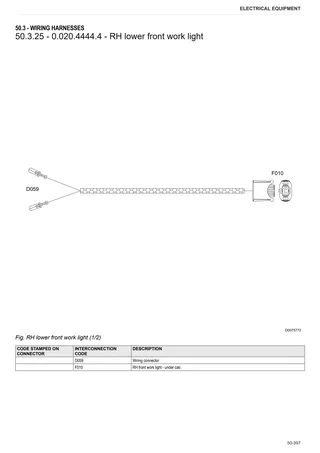
- 0.020.4444.4 – RH lower front work light
- 0.020.4444.4 – LH lower front work light
- 0.020.4445.4/10 – RH front lights
- 0.020.4445.4/10 – LH front lights
- 0.020.4446.4 – Rear lights wiring loom
- 0.020.4447.4 – Front work light on RH handrail
- 0.020.4447.4 – Front work light on LH handrail
- 0.020.4449.4 – RH roof lights
- 0.020.4449.4 – LH roof lights
- 0.020.4450.4 – Side instrument panel adapter
- 0.020.4451.4 – Side roof instrument panel adapter
- 0.020.8418.4 – Light on exhaust pipe
- 0.020.9597.4/10 – Power feeds and grounds
- 0.020.9610.4 – Rear wiring loom
- 0.020.9611.4 – Fuse box
- 0.020.9612.4 – Frame
- 0.020.9641.4 – Engine
- 04213623 – Fuel injectors – Second bank
- 04213623 – Fuel injectors – First bank
- 04217244 – Starter motor control relay
- 04218898 – Engine
- 16050256/20 – Spreader deflectors adjustment
- 16050268 – LH beater door emergency switch
- 16050274/20 – Sieve box work light
- 16056731/10 – LH side outline marker lights
- 16056731/10 – RH side outline marker lights
- 16058810 – Climate control
- 16062566/20 – Lower sieve adjustment motor
- 16062567/20 – Upper sieve adjuster motor
Calibrations and diagnostics
- Safety-Hints
- Common Hints
- Common Hints – Start and Communication
- Common Hints – Disposability
- Introduction
- Error Hints (FAQ)
- Connection establishment
- Software handling
- Software handling – Topper elements
- Global Programfunctionality – Dataset management
- Global Programfunctionality – Error memory
- Global Programfunctionality – Graphical display
- Global Programfunctionality – Program adjustments
- UseCases EMR4
- Engine settings
- Adjustments engine speed – acceleration pedal
- CRT – TIER4 interim
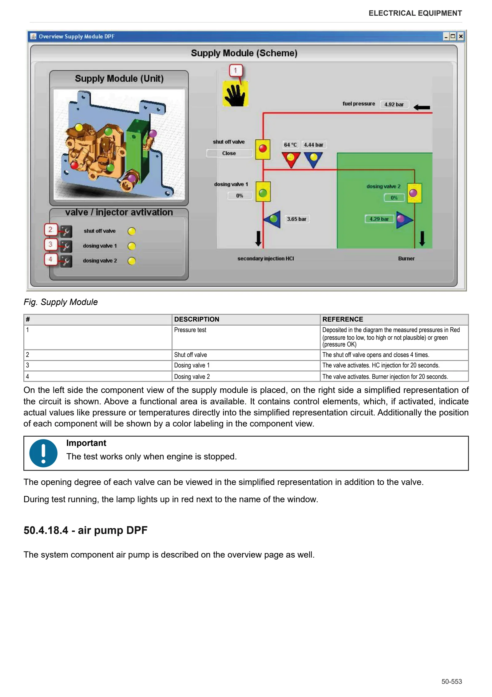
- DPF – Burner – TIER4 interim
- SCR – TIER4 interim
- SCR service routines
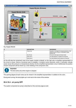
- DPF service routines
- Service Routines DPF (DOC/SCR)
- Service-Cases
- Other
- UseCases EMR3
- UseCases EMR2
- Programm options
- Engine ECU Alarms: SPN 000016-000175
- Engine ECU Alarms: SPN 000190-001188
- Engine ECU Alarms: SPN 001231-003520
- Engine ECU Alarms: SPN 003532-005763
- Engine ECU Alarms: SPN 520521-523632
- Engine ECU Alarms: SPN 523633-523918
- Engine ECU Alarms: SPN 523919-524030
- Engine ECU Alarms: SPN 524031-524108
- Engine ECU Alarms: SPN 524109-524267
Threshing unit
- Turbo separator adjustment
- Installing threshing drum – P/N 939116
Cleaning unit
- Straw walker mounts
- Fitting straw walker pulleys and belt tensioners
- Assembling sieve mount drive and grain cleaning system drive
- Straw chopper engage belt tensioning – P/N 939466
- Strawchopper pulley assembly – P/N 939441
Grain tank – Elevator
- Discharge auger assembly – P/N 939459
Service Info
C0 – ENGINE ACCESSORIES
- AdBlue feed pump cleaning
- AdBlue system trouble shooting
- Filter and prefilter tool p/n 5.9035.865.0
- Cleaning fan bearing breakage
HB – AXLES
- Adjusting rear axle toe angle
HH – ELECTRICAL SYSTEM
- Linear actuator
HL – CLEANER UNIT
- Straw walker supports assembly procedure
HM – GRAIN TANK / ELEVATOR
- Elevator and head chain tensioning
HP – CUTTER BAR
- Assembly of knife head on VX vario crop harvester