
Document overview
Digital Workshop Manual documentation for model DEUTZ FAHR C 7205 → 150000 from the C 7000 (STAGE 3A) family. Language: English; 761 pages.
The corresponding English table of contents contains 33 sections and 254 individual topics.
Main sections included
- Introduction
- Technical characteristics
- Calibrations and electronic diagnosis
- Procedure
- Wiring diagrams
- Service Info
Document details
- Brand: DEUTZ FAHR
- Family: C 7000 (STAGE 3A)
- Model: C 7205
- Starting serial number: 150000
- Document type: Workshop Manual
- Language: English
- Pages: 761
- File size: 225.82 MiB
- Format: Digital PDF download
Compatibility
Before purchasing, verify that your machine model and reference code match DEUTZ FAHR C 7205 → 150000.
Complete table of contents
Introduction
- Introduction
- Tightening Torques
- Tightening torques for nuts and bolts of electrical connections
- Wheel rim to hub screws and nuts tightening torques
- Installation of solenoid valves and cartridge valves
- Installation of quick couplers
- Safety instructions – maintenance and repair
- General safety instructions
Technical characteristics
Engine
- Engine 2013 components
- Technical data
Belts and chains
- Belts and chains
- Rotary screen filter drive belt
- Cooling fan belt
- Cooling fan belt
- Engine compartment cleaning fan drive belt
- Feed passage drive belt
- Feed passage drive belt (maize)
- Threshing drum variator adjustment chain
- Sieve-elevator auger drive chain
- Tank auger transmission chain
- Grain tank discharge chain
- Chaff spreader drive belt
- Straw chopper drive belt
- Straw chopper transmission belt
Hydraulic System
- HMF hydraulic motor
- Pump (135 cc)
- LS pump, 45 cc
- Pump (14 cc)
- Pump (19 cc)
- Hydraulic steering system
- Reverser solenoid valve block
Threshing section
- Straw beater system
Grain tank – Elevator
- Elevator auger
- Elevator head auger
Calibrations and electronic diagnosis
Diagnostic tools
- SDF Analyser
- SDF SUITE
- D-TECH App
- SerDia2010
Diagnostic tool screens
- iMonitor8
- Pop-ups
- Symbols displayed in lamp area
- Combine leveling
- Header calibration
- Header auto up
Commissioning and calibrations of the machine
- Basic procedure for startup
- EEPROM memory reset
- EEPROM memory reset of HLHP Header
- Basic settings
- CCP A calibrations
- CCP B calibrations
- Service mode
- Delete alarms
ECU alarms
- ECU ALARMS
- ATC
- CTM
- EPB_Combine
- SECU
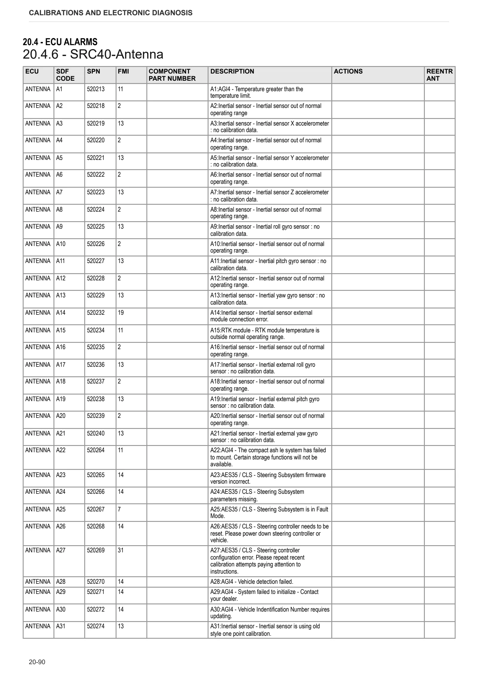
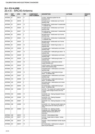
- SRC40-Antenna
- Alarm conditions and effects
- HIW – Symbols
- Alarm list codes
Engine alarms
- Engine alarms code
Procedure
Engine
- Engine
- Checking the compression pressure
- Removing and installing the crankcase bleeding
- Dismantling and assembling the crankcase breather
- Removing and installing the front cover (opposite side to flywheel)
- Removing and installing the lubricating oil pan (heavy duty version)
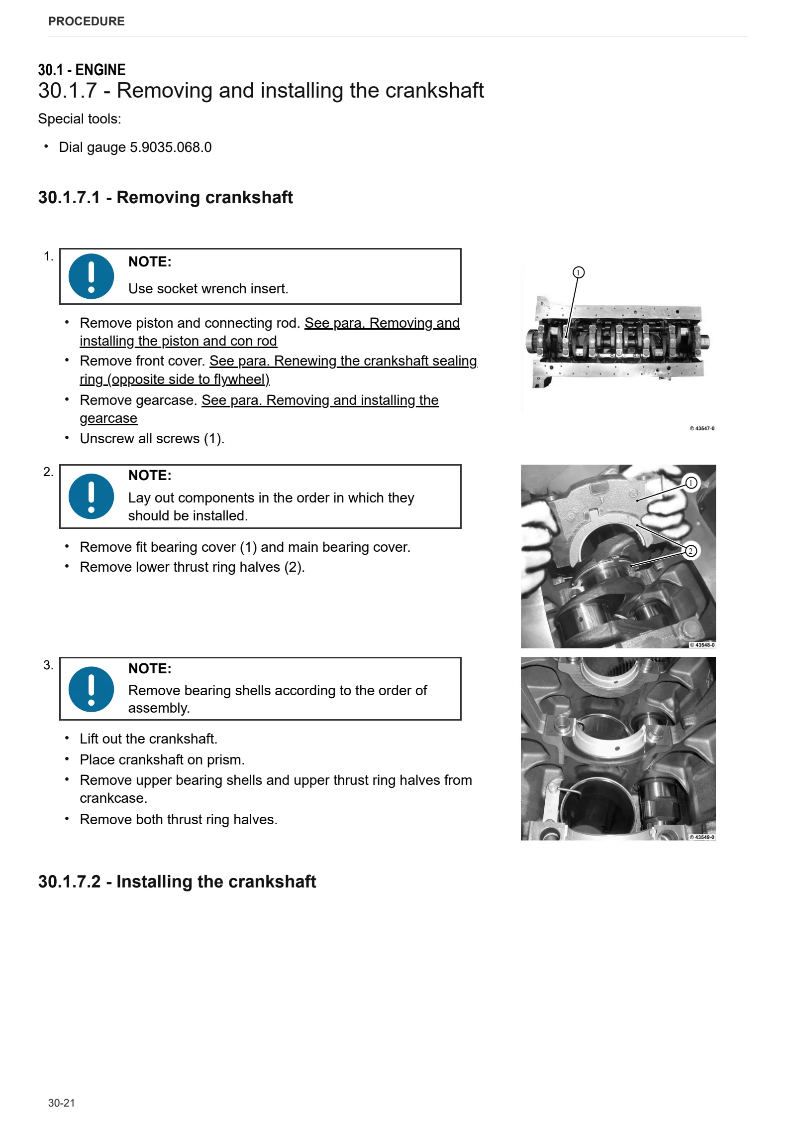
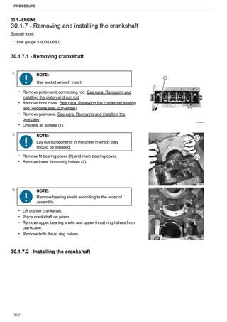
- Removing and installing the crankshaft
- Checking the axial clearance of the crankshaft
- Removing and installing torsional vibration damper
- Checking the crankshaft
- Removing and installing the flywheel
- Fluid coupling and flywheel
- Air conditioning compressor drivebelt
- Air conditioning compressor belt – Tension adjustment
- Renewing the crankshaft sealing ring (flywheel side)
- Renewing the crankshaft sealing ring (opposite side to flywheel)
- Removing and installing the piston and con rod
- Checking piston overhang
- Checking the piston
- Removing and installing the cylinder liner
- Checking the overhang of the cylinder liner
- Testing the cylinder liner
- Checking the piston rings and piston ring grooves
- Removing and installing the camshaft
- Checking the camshaft
- Removing and installing the connection housing
- Removing and installing the gearcase
- Removing and installing the valves
- Checking and setting the valve clearance
- Checking the valves
- Checking the valve lag
- Checking the valve guide
- Removing and installing the valve control
- Removing and installing cylinder head
- Removing and installing the oil cooler housing
- Removing and installing the oil cooler
- Removing and installing the control block
- Removing and installing the fuel pressure sensor
- Removing and installing the high-pressure pump (Installation position A)
- Removing and installing the high-pressure pump (Installation position B)
- Removing and installing the injector
- Removing and installing the pressure limiting valve
- Removing and installing the rail
- Removing and installing the coolant pump
- Removing and installing the cooler (exhaust gas recirculation)
- Removing and installing the flutter valve (exhaust gas recirculation)
- Removing and installing the actuator (exhaust gas recirculation)
- Checking radiator cleanliness
- Remove and install the charge air line
- Flywheel
- Removing and installing the exhaust line
- Removing and installing the shutoff valve (exhaust gas recirculation)
- Removing and installing the turbocharger
Engine accessories
- Removing and installing the fuel supply pump
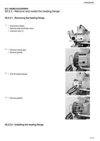
- Remove and install the heating flange
- Removing and installing the air conditioning compressor
- Removing and installing the pressure/temperature sensor (charge air)
- Removing and installing temperature transmitter
- Removing and installing the thermostat housing
- Removing and installing the thermostat
- Removing and installing the generator (operating side)
- Removing and installing the generator (outlet side)
- Removing and installing the impulse transmitter (camshaft)
- Removing and installing the impulse transmitter (crankshaft)
- Removing and installing the oil pressure switch
- Removing and installing the rail pressure sensor
- Removing and installing the starter
- Fuel tank thermal protection assembly
- Replacing the coolant
- Radiator assembly
- Disassembling the radiator assembly
- Air filter container
- Expansion tank
- Fuel tank
- Fuel prefilter
- Manual fuel delivery pump
- Exhaust pipe
- Air compressor
- Compressed air reservoir
- Compressed air pressure regulator
- Engine power take off
- Add. fan bearing
Axles
- Front axle
- Final drive unit
- Installing rotation angle transducers – P/N 939036
- Disassembling the reduction gear
- Transmission
- Disassembling the transmission
- External gearbox controls
- Parking brake
- Rear axle
- Steering bar
- Steering cylinder
- Wheel hub
- Installing telescopic tube – P/N 939589
- Front wheel
- Rear wheel
Belts and chains
- Fitting straw walker pulleys and belt tensioners
- Feed passage belt – Synchronised straw beater shaft
- Turbo-separator belt
- Feed passage belt
- Threshing drum variable speed drive – threshing drum transmission belt
- Engine power take off – Threshing drum variable speed drive belt
- Straw walker drive belt
- Straw walker transmission – fan variable transmission unit belt
- Straw beater – straw walker belt
- Straw walker – sieve transmission belt
- Recovery elevator – straw walker shaft belt
- Engine PTO – PTO transmission belt
- PTO transmission – grain tank unloader belt
- Grain tank discharge chains
- Tank auger transmission chains
- Threshing drum transmission – threshing drum belt
- Fan variable speed drive – fan belt
- Straw chopper transmission – straw chopper belt
- Straw walker shaft – chaff spreader belt
- Synchronised straw beater shaft – threshing drum transmission belt
- Straw chopper engage belt tensioning – P/N 939466
Hydraulic System
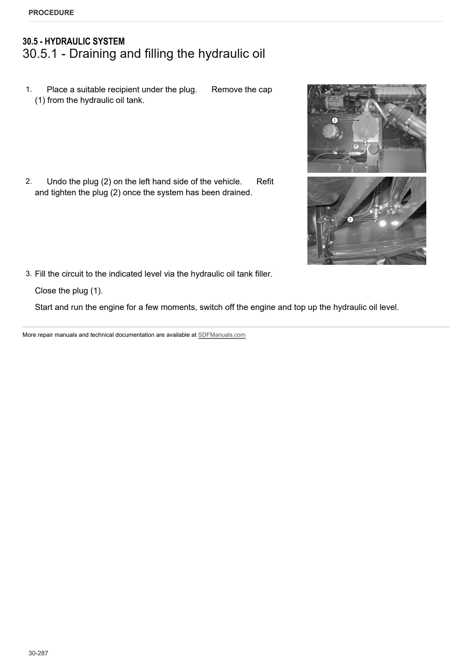
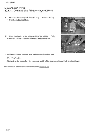
- Draining and filling the hydraulic oil
- Hydraulic oil reservoir
- Hydraulic pump
- Hydraulic motor
- Power steering
- Steering hose replacement
- Instructions for bleeding the brake system
- Brake callipers
- Brake master cylinders
- Solenoid valve unit
Feed passage
- Feed passage
- Disassembling the feed passage
- Oscillating structure
- Disassembling the feed passage
Chassis – Bodywork
- Engine hood
- Right hand hatch
- Battery mount
- Cab access steps
Cab
- Cab
- Seat
- A/C unit
- Empty and charge the air conditioning system
- Brake master cylinders
- Brake fluid reservoir
- Steering wheel
- Assembly standard for steering wheel (Agrosky) [939553]
- Steering column
- Gear selector
Electrical system
- Care and maintenance work – Electrical system
- Multifunction armrest
- Assembly standard for armrest and armrest wiring loom [939726]
Threshing section
- Stone trap
- Threshing drum
- Installing threshing drum – P/N 939116
- Disassembling the threshing drum
- Concave
- Threshing drum variator
- Adjusting the variator
- Threshing drum speed reduction
- Straw beater
- Straw beater rake
- Turbo-separator
- Turbo-separator concave
- Turbo separator adjustment
Cleaning unit
- Assembling sieve mount drive and grain cleaning system drive
- Straw walker supports assembly
- Fan – shroud
- Straw walker
- Straw walker drive shaft
- Returns pan
- Grain preparation pan
- Sieve box
- Assembling cleaning fan drum [939592]
- Fan
- Fan speed variator
- Recovery elevators
Grain tank – Elevator
- Grain elevator with elevator head
- Emptying the grain tank
- Grain discharge system
- Support for grain tank pipe, block
- Elevator for tailings return
- Grain unloader auger
Implements and accessories
- Chaff spreader
- Disassembling the chaff spreader
- Straw chopper
- Disassembling the straw chopper
- Rear hook
Wiring diagrams
- Wiring looms
Service Info
C0 – ENGINE ACCESSORIES
- Filter and prefilter tool p/n 5.9035.865.0
- Fuel Tank Blower Kit
HB – AXLES
- Balance front axle reinforcement kit
- Adjusting rear axle toe angle
HH – ELECTRICAL SYSTEM
- Linear actuator
HM – GRAIN TANK / ELEVATOR
- Elevator and head chain tensioning