Document overview
Workshop Manual PDF for DEUTZ FAHR C 6205 TS → 15000, C 6000 (STAGE 3A) family. Document language: English; 709 pages.
The corresponding English table of contents contains 31 sections and 211 individual topics.
Main sections included
- Introduction
- Technical characteristics
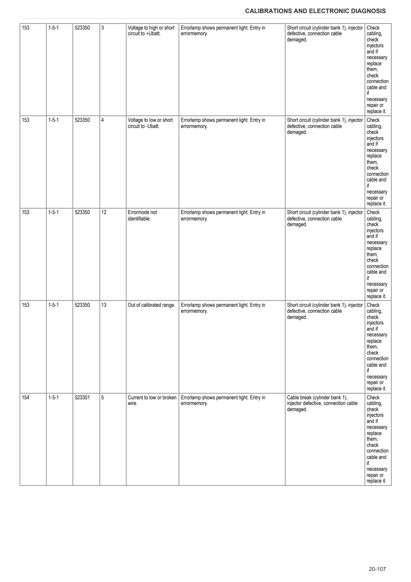
- Calibrations and electronic diagnosis
- Procedure
- Wiring diagrams
- Service Info
Document details
- Brand: DEUTZ FAHR
- Family: C 6000 (STAGE 3A)
- Model: C 6205 TS
- Starting serial number: 15000
- Document type: Workshop Manual
- Language: English
- Pages: 709
- File size: 136.00 MiB
- Format: Digital PDF download
Compatibility
Before purchasing, verify that your machine model and reference code match DEUTZ FAHR C 6205 TS → 15000.
Complete table of contents
Introduction
- Introduction
- Tightening Torques
- Tightening torques for nuts and bolts of electrical connections
- Wheel rim to hub screws and nuts tightening torques
- Installation of solenoid valves and cartridge valves
- Installation of quick couplers
- Safety instructions – maintenance and repair
- General safety instructions
Technical characteristics
Engine
- Components of the TCD 2012 L04/L06 2V DCR engine
- Test and adjustment data (L3)
- Tightening requirements TCD 2012 L04/L06 2V DCR engine
Calibrations and electronic diagnosis
Diagnostic tools
- SDF Analyser
- SDF SUITE
- D-TECH App
- SerDia2010
Diagnostic tool screens
- Combine leveling
- Header calibration
- Header auto up
Commissioning and calibrations of the machine
- Basic procedure for startup
- EEPROM memory reset
- EEPROM memory reset of HLHP Header
- Basic settings
- CCP A calibrations
- CCP B calibrations
- Service mode
- Delete alarms
ECU alarms
- ECU ALARMS
- ATC
- SECU
Engine alarms
- Engine alarms code
- Alarm list codes
Procedure
- Tools for engine disassembly and reassembly
- Workshop tools for engine disassembly and reassembly
Engine
- Air conditioning compressor drive belt
- Tension adjustment of the fan and air conditioning compressor drive belt
- Alternator, fuel pump and water pump drive belt
- Tension adjustment of the alternator, fuel pump and water pump drive belt
- Check the compression value (L3)
- Assembly and disassembly of the engine on the assembly stand (L3)
- Valve clearance adjustment (with the exhaust gas recirculation module absent or removed) (L3)
- Valve clearance adjustment (with the exhaust gas recirculation module installed) (L3)
- Disassembly and assembly of the rocker and support (L3)
- Disassemble and complete the rocker and support, check
- Disassembly and assembly of the cylinder head (L3)
- Valve assembly and disassembly (L3)
- Valve check (L3)
- Check the valve guide (L3)
- Check the valve residual (L3)
- Crankshaft check (L3)
- Replace the crankshaft O-ring (flywheel end) (L3)
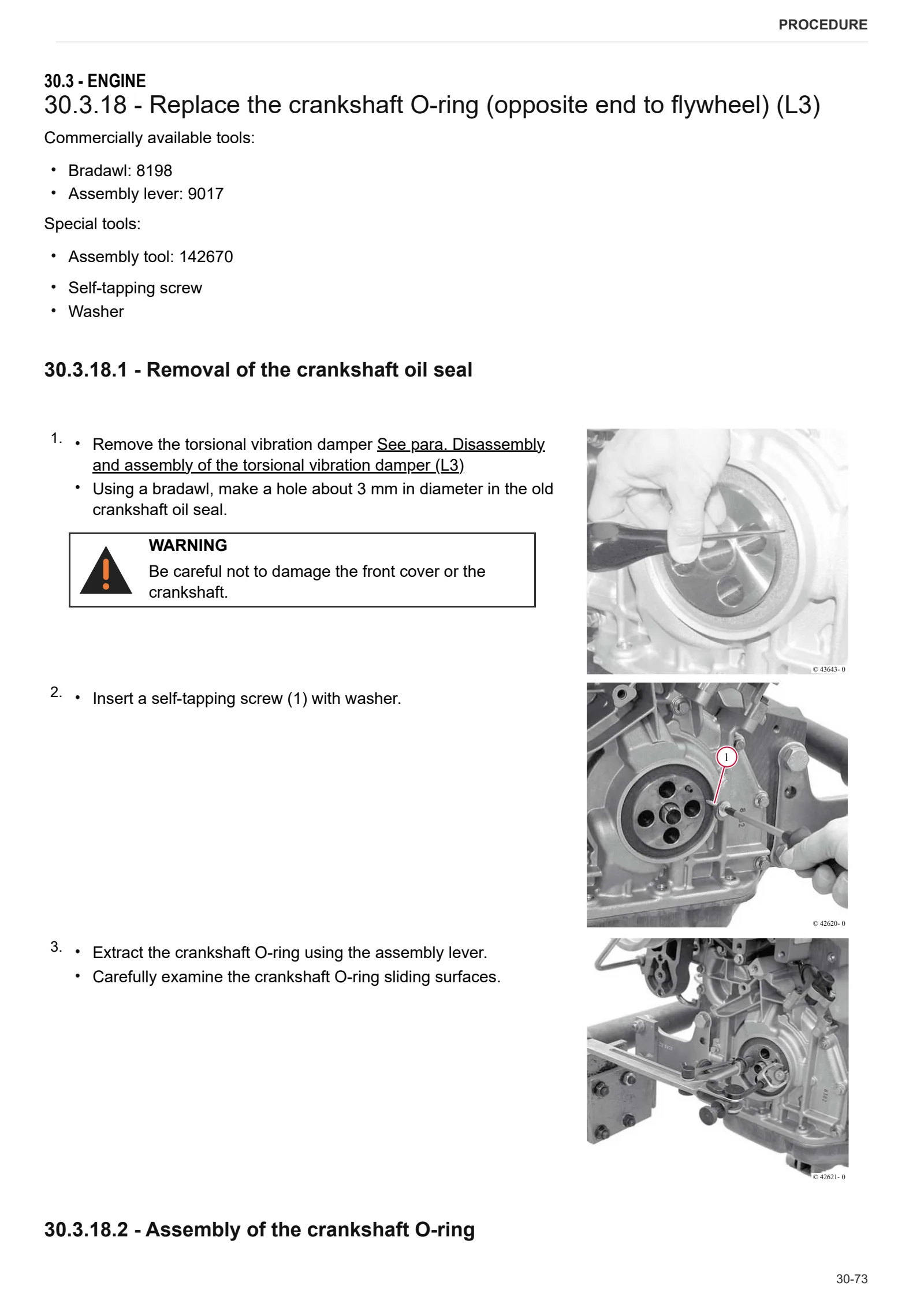
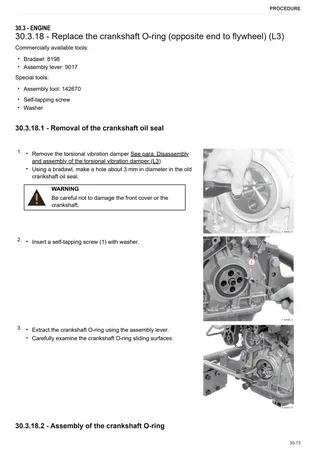
- Replace the crankshaft O-ring (opposite end to flywheel) (L3)
- Connecting rod drum check (L3)
- Assembly and disassembly of the crankshaft (L3)
- Disassembly and assembly of the piston and connecting rod drum (L3)
- Check the piston (L3)
- Check the piston rings and piston grooves (L3)
- Assembly and disassembly of the piston cooling nozzles (L3)
- Removing and fitting crankcase breather (L3)
- Checking cylinder (L3)
- Removal and refitting of the front cover (opposite end to flywheel) (L3)
- Disassembly and assembly of the connector box (L3)
- Disassembly and assembly of the gear case cover (L3)
- Assembly and disassembly of the camshaft (L3)
- Check the camshaft (L3)
- Disassembly and assembly of the turbocharger (L3)
- Disassembly and assembly of the turbocharging air duct (L3)
- Fitting and removing the exhaust gas recovery module (L3)
- Removing and fitting the fuel delivery pump (driven by ribbed V-belt) (L3)
- Removing and fitting the fuel control unit (L3)
- Removing and fitting high pressure pump (installation position A) (L3)
- Removing and fitting high pressure pump (installation position B) (L3)
- Removing and fitting the common rail system (L3)
- Removing and fitting injector (L3)
- Removing and fitting the pressure cut-off valve (L3)
- Removing and fitting the fuel pressure transducer (L3)
- Assembly and disassembly of the oil intake pipe (L3)
- Disassembly and assembly of the lubricant oil sump (L3)
- Disassembly and assembly of the oil radiator (L3)
- Removing and fitting the lubricant oil cooler housing (L3)
- Removing and fitting the lubricant oil filter (L3)
- Removing and fitting the oil pressure switch (L3)
- Removing and fitting reservoir (L3)
- Removing and fitting the coolant pump (driven by ribbed V-belt) (L3)
- Removing and refitting fan motor (L3)
- Removing and fitting fan motor (L3)
- Removing and fitting fan mount (L3)
- Disassembly and assembly of the torsional vibration damper (L3)
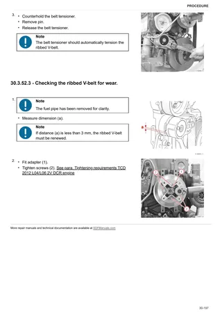
- Removing and fitting belt tensioner (ribbed V-belt) (L3)
- Assembly and disassembly of the flywheel (L3)
Engine accessories
- Starter motor
- Fitting and removing thermostat (L3)
- Testing the thermostat (after removal)
- Removal and refitting of the crankshaft speed sensor (L3)
- Removal and refitting of the camshaft speed sensor (L3)
- Removing and refitting the exhaust manifold (L3)
- Fitting and removing the solenoid valve (exhaust gas recovery module) (L3)
- Removing and fitting the fuel filter mount (L3)
- Assembly and disassembly of the temperature sender (L3)
- Removal and refitting of the supply air pressure/temperature sender (L3)
- Removing and fitting the alternator (driven by ribbed V-belt) (L3)
- Fitting and removing the rail pressure sensor (L3)
- Disassembly and assembly of the cable bundle (L3)
- Disassembly and assembly of the starter (L3)
- Fitting and removing the glow plugs (L3)
- Replacing the coolant
- Engine fan
- Complete radiator pack
- Air filter container
- Expansion tank
- Fuel tank
- Fuel pre-filter
- Manual fuel pump
- Air compressor for utilities
Axles
- Front axle
- Final drive unit
- Transmission
- Disassembling the transmission
- Wheel hub
- Front wheel
- Rear wheel
Belts and chains
- Treshing drum clutch
- Feeder channel clutch
- Grain tank discharging clutch
- Chopper clutch
- Fitting straw walker pulleys and belt tensioners
- Feed passage belt – Synchronised straw beater shaft
- Turbo-separator belt
- Feed passage belt
- Threshing drum variable speed drive – threshing drum transmission belt
- Engine power take off – Threshing drum variable speed drive belt
- Straw walker drive
- Straw beater – straw walker belt
- Straw walker – sieve transmission belt
- Recovery elevator – straw walker shaft belt
- Engine PTO – PTO transmission belt
- PTO transmission – grain tank unloader belt
- Tank auger transmission chains
- Fan variable speed drive – fan belt
- Straw chopper transmission – straw chopper belt
- Straw walker shaft – chaff spreader belt
- Straw chopper engage belt tensioning – P/N 939466
Hydraulic System
- Draining and filling the hydraulic oil
- Hydraulic oil reservoir
- Hydraulic pump
- Hydraulic motor
- Power steering
- Instructions for bleeding the brake system
- Brake calliper
- Brake master cylinder
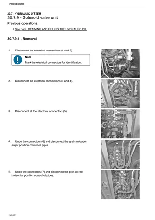
- Solenoid valve unit
Feed passage
- Feed passage
- Disassembling the feed passage
- Oscillating structure
- Feeder channel chain tension
Chassis – Bodywork
- Engine cowl
- Right hand hatch
- Rear cover
- Left hand hatch
- Cab access ladder
Cab
- Cab
- Seat
- A/C unit
- Empty and charge the air conditioning system
- Steering wheel
- Mechanical gear selector controls
Electrical system
- Care and maintenance work – Electrical system
Threshing section
- Stone trap
- Threshing drum
- Disassembling the threshing drum
- Concave
- Threshing drum speed variator
- Variator adjustment
- Threshing drum speed reduction
- Straw beater
- Straw beater rake
- Turbo-separator
- Turbo-separator concave
- Turbo separator adjustment
Cleaning unit
- Assembling sieve mount drive and grain cleaning system drive
- Straw walker supports assembly
- Fan – shroud
- Straw walker
- Straw walker drive shaft
- Returns pan
- Sieve box
- Sieve box
- Fan
- Fan speed variator
- Recovery elevators
Grain tank – Elevator
- Grain elevator with elevator head
- Emptying the grain tank
- Grain discharge system
- Support for grain tank pipe, block
- Elevator for tailings return
- Grain unloader auger
- Exhaust pipe
- Disassembling the unloading auger
Implements and accessories
- Chaff spreader
- Disassembling the chaff spreader
- Straw chopper
- Disassembling the straw chopper
- Rear hook
Wiring diagrams
- Wiring looms
Service Info
HB – AXLES
- Balance front axle reinforcement kit
- Adjusting rear axle toe angle
HG – CAB
- Gear lever KIT assembly instruction
HH – ELECTRICAL SYSTEM
- Consent Button
- Linear actuator
HL – CLEANER UNIT
- Straw walker supports assembly procedure
HM – GRAIN TANK / ELEVATOR
- Elevator and head chain tensioning
HP – CUTTER BAR
- Assembly of knife head on VX vario crop harvester