
Document overview
Workshop Manual for DEUTZ FAHR C 6205 → 18000 from the C 6000 (STAGE 4) family. Digital PDF in English with 1,292 pages.
The corresponding English table of contents contains 37 sections and 502 individual topics.
Main sections included
- Introduction
- Technical characteristics
- Calibrations and electronic diagnosis
- Procedure
- Wiring diagrams
- Service Info
Document details
- Brand: DEUTZ FAHR
- Family: C 6000 (STAGE 4)
- Model: C 6205
- Starting serial number: 18000
- Document type: Workshop Manual
- Language: English
- Pages: 1,292
- File size: 286.35 MiB
- Format: Digital PDF download
Compatibility
Before purchasing, verify that your machine model and reference code match DEUTZ FAHR C 6205 → 18000.
Complete table of contents
Introduction
- Introduction
- Tightening Torques
- Tightening torques for nuts and bolts of electrical connections
- Wheel rim to hub screws and nuts tightening torques
- Installation of solenoid valves and cartridge valves
- Installation of quick couplers
- Safety instructions – maintenance and repair
- General safety instructions
Technical characteristics
Engine
- Technical data – Pressure/temperature transmitter
- Technical data – Pressure transducer
- Pressure transducer
- Technical data – Pressure transducer
- Pressure sensor
- Technical data – Pressure transducer
- Pressure transducer
- Technical data – Pressure sensor
- Technical data – Temperature transmitter
- Technical data – Temperature transmitter
- Technical data – Temperature transmitter
- Temperature sender
- Technical data – Temperature transmitter
- Technical data – Temperature transmitter
- Technical data – Speed indicator
- Technical data – Speed indicator
- Technical data – Speed indicator
- technical specifications – NOx sensor (24 V)
- technical specifications – NOx sensor (12 V)
Hydraulic System
- Hydraulic circuit diagram – Version without “Lateral tilt”
- Hydraulic circuit diagram – Version with “Lateral tilt”
Calibrations and electronic diagnosis
Diagnostic tools
SDF Analyser
- SDF Analyser
Diagnostic tool screens
- HLHP home screen
- HLHP monitor menu
- HLHP calibration menu
ECU alarms
Engine alarms
- Engine ECU Alarms: SPN 000016-000175
- Engine ECU Alarms: SPN 000190-001188
- Engine ECU Alarms: SPN 001231-003520
- Engine ECU Alarms: SPN 003532-005763
- Engine ECU Alarms: SPN 520521-523632
- Engine ECU Alarms: SPN 523633-523918
- Engine ECU Alarms: SPN 523919-524030
- Engine ECU Alarms: SPN 524031-524108
- Engine ECU Alarms: SPN 524109-524267
Procedure
Engine
- ENGINE
- Disassembling and assembling alternator (poly-V-belt, level 1)
- Disassembling and assembling crankcase breather
- Replacing the crankshaft O-ring (opposite end to flywheel)
- Disassembling/assembling crankshaft wear sleeve (side opposite flywheel)
- Disassembling and assembling the front cover (fixing elements)
- Assembly and disassembly of piston cooling nozzles
- Assembly and disassembly of piston cooling nozzles
- Checking the camshaft bearing
- Removing and refitting crankshaft bearing cap
- Blanking elements
- Blanking elements
- Blanking elements
- Blanking elements
- Oil dipstick
- Oil dipstick
- Pipe (crankcase breather)
- Disassembling and assembling the lubricant oil sump (pressed steel sump)
- Removing and fitting lubricant oil sump (heavy version)
- Removing and fitting lubricant oil sump (heavy version)
- Removing and fitting lubricant oil sump (heavy version)
- Oil filler neck
- Disassembling and assembling the torsional vibration damper
- Disassembling and assembling the torsional vibration damper
- Disassembling and assembling the torsional vibration damper
- Disassembling and assembling the flywheel (fixing elements)
- Replacing the starter motor ring gear on the flywheel
- Removing and fitting the crankshaft
- Check the crankshaft
- Check the endfloat of the crankshaft
- Assembly and disassembly of the crankshaft bearing
- Check the crankshaft bearings
- Disassembly and reassembly of connecting rod shank
- Check the connecting rod shank
- Disassembling and assembling the piston
- Check the piston
- Check the piston
- Disassembling and assembling the piston rings
- Check the piston rings
- Check the piston rings
- Check the piston rings
- Compression test
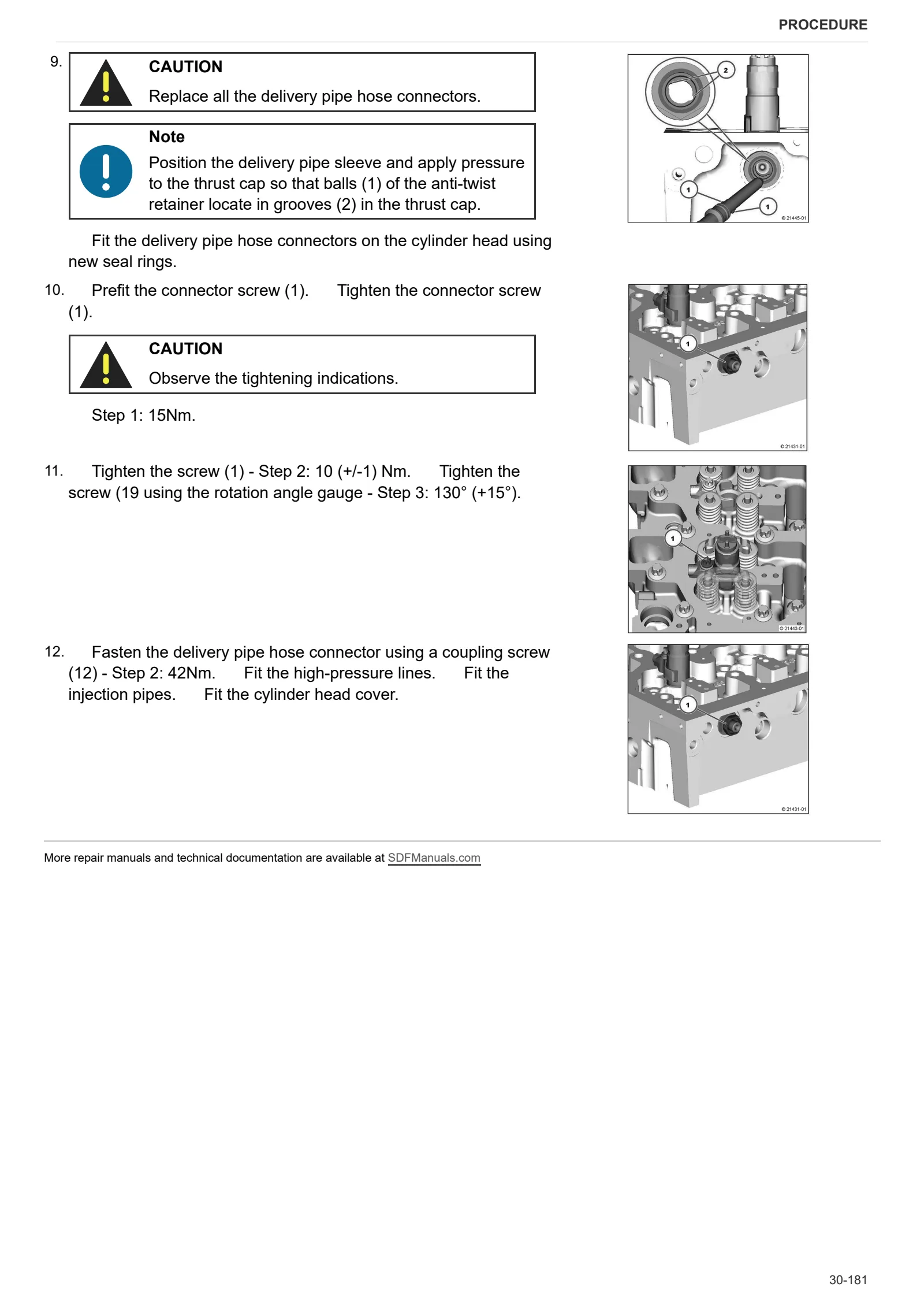
- Removing and fitting the cylinder head cover
- Disassembling and assembling the cylinder head (fasteners)
- Measuring piston protrusion
- Assembly and disassembly of the valves
- Checking valves, valve guides, valve springs and valve recess
- Replacing the injector bush
- Clean the injector bush
- Clean the injector bush seat
- Blanking elements (cylinder head)
- Eye-bolt for transporting (cylinder head)
- Eye-bolt for transporting (cylinder head)
- Replace the crankshaft O-ring (flywheel end)
- Disassembling and assembling the gearbox
- Assembly and disassembly of the camshaft
- Check the camshaft
- Checking and setting valve clearance (6 cylinder)
- Assembly and disassembly of the distribution valve
- Removing and refitting the valve timing system
- Disassembly and assembly of the control elements
- Disassembling and assembling the oil cooler
- Removing and fitting the lubricant oil radiator
- Removing and fitting the lubricant oil radiator
- Disassembling and assembling the lubricant oil radiator (blanking elements)
- Removing and fitting the lubricant oil radiator housing
- Removing and fitting the lubricant oil radiator housing (fastener elements)
- Blanking elements (lubricant oil cooler housing)
- Blanking elements (lubricant oil cooler housing)
- Coolant pipe (lubricant oil radiator housing – crankcase)
- Coolant pipe (Lubricant oil cooler – cylinder head)
- Disassembling and assembling the oil suction pipe
- Disassembly and assembly of the fuel control unit (fastening elements)
- Disassembly and completion of the fuel control unit
- Disassembling and completing assembly of the fuel control unit (2000 bar injection system)
- Disassembling and assembling the high pressure pump (fastener elements)
- Disassembling and assembling the injector (1600 bar injection system)
- Disassembling and assembling the injector (1600 bar injection system)
- Flexible hose connectors
- Connector plug (fuel delivery pump)
- Removing and refitting fuel lines (fuel delivery pump – pilot block)
- Disassembling and assembling the fuel line (fuel control block – high pressure pumps)
- Disassembling and assembling the rail (1600 bar injection system)
- Disassembling and assembling the rail (1600 bar injection system)
- Disassembling and assembling the rail (2000 bar injection system)
- Disassembling and assembling the pressure cut-off valve (rail)
- Disassembling and assembling the pressure cut-off valve (rail)
- Disassembly and assembly of the rail pressure sensor
- Disassembly and assembly of the rail pressure sensor
- Removing and refitting fuel lines (Rail, cylinder head, fuel control unit – fuel filter)
- Fuel pipes (Fuel pump, fuel filter, pilot lock)
- Fuel pipes (Rail, cylinder head, pilot lock- fuel filter)
- Vibration damper (installation position)
- Disassembling and assembling charge air pipe
- Disassembling and assembling charge air pipe
- Removing and fitting the coolant pump
- Disassembling and assembling coolant pipe (ribbed V-belt, level 1)
- Removing and fitting the coolant pump (fastening elements)
- Removing and refitting adapter (coolant pump – thermostat housing)
- Transmission components (coolant pump)
- V-belt pulley
- Assembling and disassembling the thermostat
- Assembling and disassembling the thermostat
- Disassembling and assembling the thermostat
- Check the thermostat (after removing)
- Check the thermostat (after removing)
- Removal and installation of the thermostat housing
- Removal and installation of the thermostat housing
- Removal and installation of the thermostat housing
- Disassembling and assembling the thermostat housing (fastener elements)
- Blanking elements (coolant pump – thermostat housing)
- Blanking elements (thermostat housing)
- Blanking elements (thermostat housing)
- Blanking elements (thermostat housing)
- Blanking elements (thermostat housing)
- Blanking elements (thermostat housing)
- Flexible hose fastening (Thermostat housing)
- Flexible hose connector (thermostat box)
- Connection (compensation line)
- Breather pipe (thermostat box – cooler)
- Pipes (AGR radiator cylinder head)
- Compensation line (thermostat box)
- Removing and fitting belt tensioner (ribbed V belt)
- Disassembly and refitting of the belt tensioner (ribbed V-belt, level 1)
- Disassembly and refitting of the belt tensioner (ribbed V-belt, level 1)
- Removal and assembly of the fan support
- Removal and assembly of the fan support
- Removal and assembly of the fan support
- Removal and assembly of the fan support
- Fastener elements (fan mount)
- Disassembling and assembling the exhaust manifold
- Disassembling and assembling the exhaust manifold
- Removal and installation of the exhaust pipe (auxiliaries)
- Disassembling and assembling the exhaust manifold
- Assembling and disassembling the console
- Disassembling and assembling the butterfly valve
- Disassembling and assembling the butterfly valves
- Disassembling and assembling the radiator
- Removing and fitting the exhaust gas recirculation (EGR) radiator
- Disassembling and assembling the regulator
- Disassembling and assembling the regulator
- Disassembling and assembling the Venturi pipe
- Disassembling and assembling the Venturi pipe
- Removing and fitting the pipes (cylinder head – radiator, radiator – cylinder head).
- Exhaust gas pipe (Venturi tubes – mixing tubes)
- Pipe (exhaust pipe – pressure transducer)
- Pipe (exhaust pipe – pressure transducer)
- Disassembling and assembling the turbocharger
- Disassembling and assembling the turbocharger
- Disassembling and assembling the turbocharger
- Disassembling and assembling the lubricating oil pipe (exhaust gas turbocharger)
- Disassembling and assembling the lubricating oil pipe (exhaust gas turbocharger)
- Removing and refitting the lubricant oil return pipe – (upper section) – (turbocharger)
- Removing and refitting the lubricant oil return pipe – (upper section) – (turbocharger)
- Disassembling and assembling the lubricating oil return pipe (turbocharger)
- Removing and refitting the lubricant oil return pipe – (lower section) – (turbocharger)
- Removing and refitting the lubricant oil return pipe – (lower section) – (turbocharger)
- Removing and refitting the lubricant oil return pipe – (lower section) – (turbocharger)
- Disassembling and assembling alternator (poly-V-belt, level 1)
- Disassembling and assembling alternator (poly-V-belt, level 1)
- Removing and fitting the V belt pulley/poly-V belt pulley (alternator)
- Disassembling and assembling the console (ribbed V-belt, level 1)
- Disassembling and assembling the console (ribbed V-belt, level 1)
- Disassembling and assembling the console (ribbed V-belt, level 1)
- Disassembling and assembling the console (ribbed V-belt, level 1)
- Fitting and removing the rotation device (PTOC)
- Fitting and removing the rotation device
- Disassembling and assembling the connector housing
- Cover (connector casing)
- Cover (connector casing)
- Cover (connector casing)
- Disassembling and assembling the heater
- Disassembling and assembling the heater
- Disassembling and assembling the heater
- Removing and fitting the charge air elbow pipe
- Disassembling and assembling the mixer pipe
- Disassembling and assembling the mixer pipe
- Disassembling and assembling the butterfly valve
- Disassembling and assembling the butterfly valve
- Disassembly and assembly of the flange
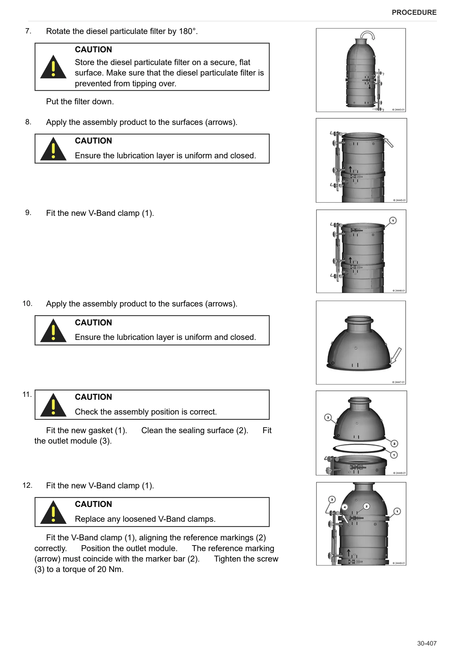
- Removing and refitting the diesel particulate filter
- Removing and fitting the diesel particulate filter (9.5 ” axial and radial system – removed)
- Disassembling and assembling the NOx sensor
- Pressure transducer (exhaust back-pressure).
- Fitting the SCR (Selective Catalytic Reduction) dosing unit
- Cleaning the SCR delivery pump (Selective Catalytic Reduction)
- Cleaning/Checking SCR (Selective Catalytic Reduction) metering unit
- Cleaning the SCR (Selective Catalytic Reduction) pipe (delivery pump – metering unit)
- Blanking elements (diesel oxidation catalytic converter/diesel particulate filter, SCR catalytic converter)
- Cover guard (Differential pressure transducer)
- Mount (Exhaust after-treatment system 9.5″)
- SCR (Selective Catalytic Reduction) urea solenoid valve
- SCR delivery pump (Selective Catalytic Reduction)
- Outlet module particulate filter
- Mixer pipe (threaded connection) SCR (Selective Catalytic Reduction)
- Mixer pipe (fastening element) SCR (Selective Catalytic Reduction)
- Blanking elements (crankcase, PTO-A)
- Closing elements (Power Take-Off PTO-B)
- Closing elements (Power Take-Off PTO-B)
- Blanking elements (gearbox, PTO-C)
- Blanking elements (gearbox, PTO-C)
Engine accessories
- Replacing the coolant
- Engine fan
- Disassembling the radiator assembly
- Air filter container
- Expansion tank
- Fuel tank
- AdBlue tank
- AdBlue pump module
- Air conditioning compressor
- Engine power take off
- Removing and fitting the fuel filter head
- Disassembling and assembling the fuel delivery pump (fastener elements)
- Fuel filter
- Manual fuel pump
- Filter holder
- Assembly of the pressure transducer (fuel pressure)
- Disassembly and refitting of the intake air pressure/temperature sender
- Blanking elements (mixer pipe, intake air)
- Shield plate (exhaust gas back-pressure sensor)
- Turbocharger shield plate
- Support plate (exhaust gas back-pressure relay – sensor)
- Support (shield plate)
- Pressure transducer (exhaust back-pressure).
- Pressure transducer (exhaust back-pressure).
- Connector manifold (intake air)
- Connector manifold (intake air)
- Intake manifold (exhaust gas turbocharger)
- Removing and fitting the fan mount (fastener elements)
- Removing and fitting the fan mount (fastener elements)
- Removing and fitting the temperature sender
- Removing and fitting the pressure transducer
- Mount (radiator – exhaust gas recirculation)
- Mount (radiator – exhaust gas recirculation)
- Pressure transducer/Duct (exhaust gas back-pressure).
- Pressure transducer/Duct (exhaust gas back-pressure).
- Disassembling and assembling the pressure transducer (exhaust back-pressure)
- Connection (Starter)
- Connection (Starter)
- Shield plate (starter)
- Alternator
- Starter (fasteners)
- Mount (Assembly foot, side opposite of the flywheel)
- Mount (assembly foot, side opposite of the flywheel)
- Mount (assembly foot, flywheel side)
- Disassembling and assembling the crankshaft speed sensor (fastener elements)
- Disassembling and assembling the crankshaft speed sensor (fasteners)
- Disassembling and assembling the crankshaft speed sensor (fasteners)
- Disassembling and assembling the camshaft speed sensor (ancillaries)
- Disassembly and refitting of the intake air pressure/temperature sender
- Fastener elements (wiring bundle)
- Fastener elements (wiring bundle)
- Fastener elements (wiring bundle)
- Support plate (on the charge air pipe)
- Support (wiring harness)
- Temperature sender (coolant)
- Fitting the pressure transducer (fuel pressure / lubricant oil pressure)
- Relay (heater, thermo-starter, glow plugs)
- Connector cable (relay – alternator)
- Connector cable (relay – heater)
- Protective cap (relay)
- Heater (connector line)
- Check the seal of the cooling system
- Differential pressure sender (diesel particulate filter)
- Differential pressure sender (diesel particulate filter)
- Temperature sender (upstream of the SCR catalytic converter)
- Temperature sender (ahead of and after diesel oxidation catalytic converter)
- Temperature sender (exhaust gas)
- Temperature sender (inlet air and ambient air temperature)
- V-Band clamp.
- VBand clamp (4″ exhaust pipe)
- VBand clamp (turbocharger)
- Mount (exhaust gas back-pressure sensor)
Axles
- Installing telescopic tube – P/N 939431
- Front axle
- Final drive unit
- Transmission
- Rear axle
- Wheel hub
- Front wheel
- Rear wheel
Belts and chains
- Clutch calibration
- Treshing drum clutch
- Feeder channel clutch
- Grain tank discharging clutch
- Chopper clutch
- Fitting straw walker pulleys and belt tensioners
- Feed passage belt – Synchronised straw beater shaft
- Turbo-separator belt
- Feed passage belt
- Threshing drum variable speed drive – threshing drum transmission belt
- Threshing drum transmission – threshing drum belt
- Straw walker transmission – fan variable transmission unit belt
- Engine power take off – Threshing drum variable speed drive belt
- Straw walker drive
- Straw beater – straw walker belt
- Straw walker – sieve transmission belt
- Recovery elevator – straw walker shaft belt
- Engine PTO – PTO transmission belt
- PTO transmission – grain tank unloader belt
- Tank auger transmission chains
- Fan variable speed drive – fan belt
- Straw chopper transmission – straw chopper belt
- Straw walker shaft – chaff spreader belt
- Straw chopper engage belt tensioning – P/N 939466
Hydraulic System
- Draining and filling the hydraulic oil
- Hydraulic oil reservoir
- Hydraulic pump
- Hydraulic motor
- Power steering
- Instructions for bleeding the brake system
- Brake calliper
- Brake master cylinder
- Solenoid valve unit
Feed passage
- Feed passage
- Oscillating structure
- Disassembling the feed passage
Chassis – Bodywork
- Engine cowl
- Right hand hatch
- Rear cover
- Left hand hatch
- Glove compartment
- Cab access ladder
Cab
- Cab
- Centre console
- Cab roof
- Seat
- Empty and charge the air conditioning system
- A/C unit
- Steering wheel
- Steering column
- Mechanical gear selector controls
Electrical system
- Multifunction armrest
- Assembly standard for armrest and armrest wiring loom [939726]
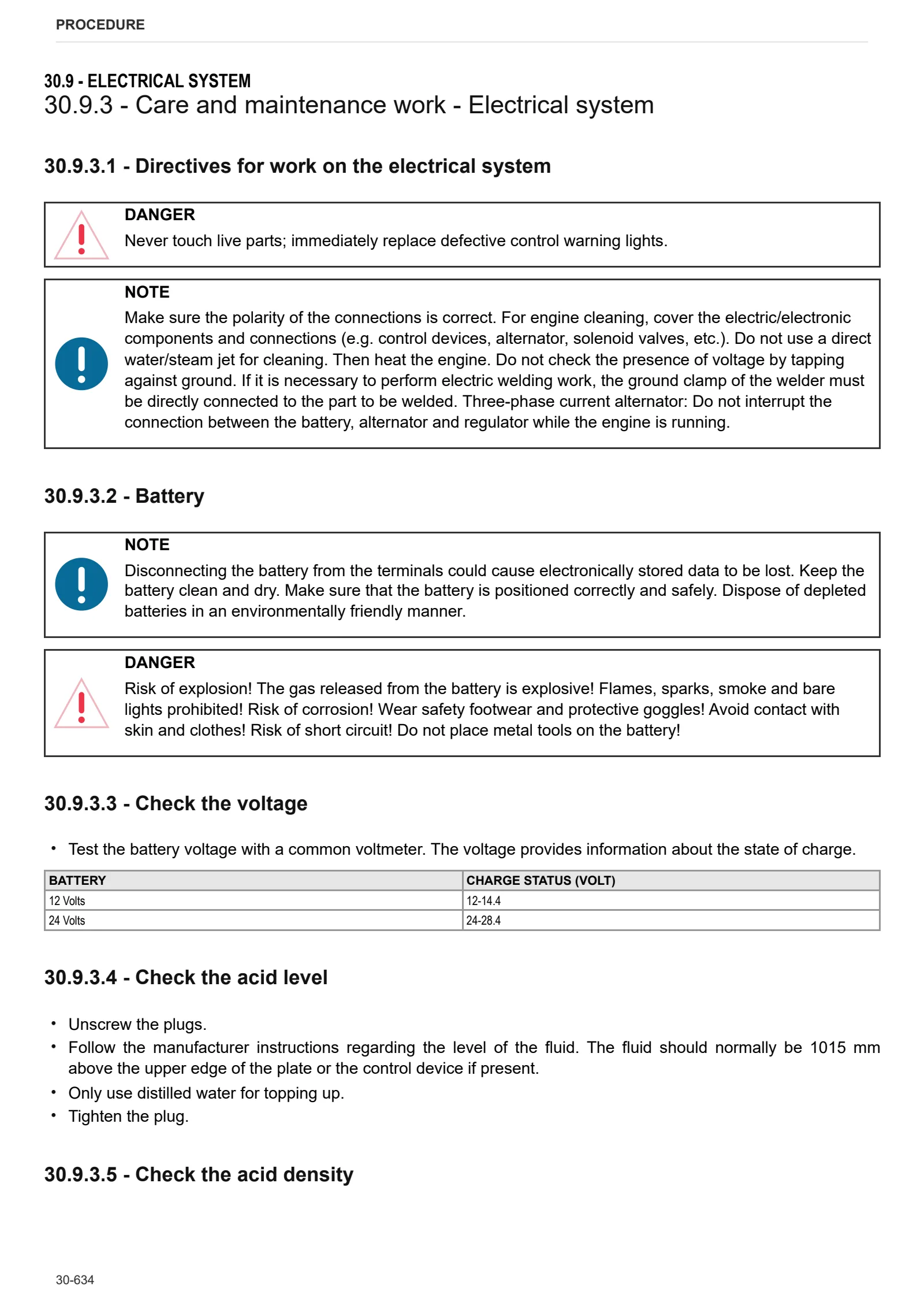
- Care and maintenance work – Electrical system
- Engine dataset upgrade
Threshing section
- Stone trap
- Threshing drum
- Disassembling the threshing drum
- Concave
- Threshing drum speed variator
- Variator adjustment
- Threshing drum speed reduction
- Straw beater
- Turbo-separator
- Turbo-separator concave
- Straw beater rake
- Turbo separator adjustment
Cleaning unit
- Assembling sieve mount drive and grain cleaning system drive
- Straw walker supports assembly
- Fan – shroud
- Straw walker
- Straw walker drive shaft
- Returns pan
- Sieve box
- Sieve box
- Fan
- Fan speed variator
- Recovery elevators
Grain tank – Elevator
- Grain elevator with elevator head
- Emptying the grain tank
- Grain discharge system
- Support for grain tank pipe, block
- Elevator for tailings return
- Disassembling the elevator head
- Grain unloader auger
- Exhaust pipe
- Disassembling the unloading auger
Cutter bar
- Disassembling the cutter bar
- Slipping clutch for intake auger and reel
- Intake auger settings
- Corn adaptation
- Assembly of potentiometer for cutting table adjustment
Implements and accessories
- Chaff spreader
- Disassembling the chaff spreader
- Straw chopper
- Disassembling the straw chopper
- Rear hook
- Strawchopper pulley assembly – P/N 939441
Wiring diagrams
Introduction
- Introduction
- Basic electronics for mechanics (1/2)
- Electrical and electronic components (1/2)
- Basic electronics for mechanics (2/2)
- Electrical and electronic components (2/2)
Components
- 2.8519.074.0/80 – HLHP control unit
- A – Starting and charging
- B – Fuses
- C – Grounds
- D – Intermediate connections
- E – On-board instruments and visual and audible indicators
- F – External lights
- G – Interior lights
- I – Circuit breakers
- J – Relays
- K – Sensors and transmitters
- L – Electromagnets and solenoid valves
- M – Electrical/electronic devices, flasher units and timers
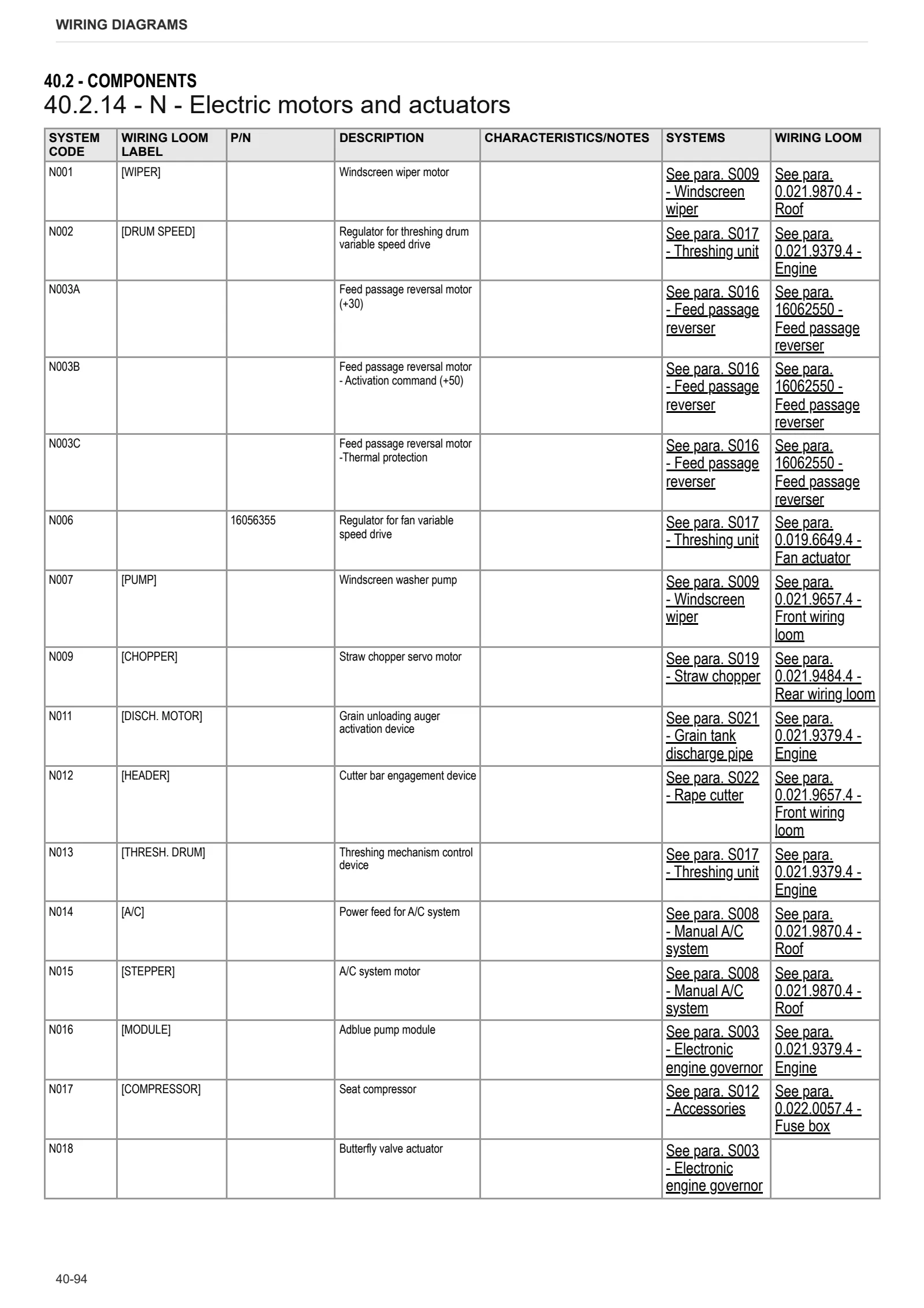
- N – Electric motors and actuators
- O – Resistors, rheostats, diodes and diode boards
- P – Various services
- Q – Safety devices
- R – Diagnostics
- T – Power supply points
Systems
- S001 – Battery master switch
- S002 – Starter
- S003 – Electronic engine governor
- S004 – Brakes
- S005 – Transmission
- S006 – Work lights
- S007 – Road lights and horn
- S008 – Manual A/C system
- S009 – Windscreen wiper
- S010 – Rear-view mirrors
- S011 – Instrument cluster
- S012 – Accessories
- S013 – Can Bus
- S014 – Pick-up reel
- S015 – Float and lateral rotation
- S016 – Feed passage reverser
- S017 – Threshing unit
- S018 – Straw walker and grain loss
- S019 – Straw chopper
- S020 – Grain tank
- S021 – Grain tank discharge pipe
- S022 – Rape cutter
Wiring looms
- 0.016.6232.4/10 – Straw walker sensor
- 0.016.6237.4/10 – Recovery elevator emergency stop switch
- 0.017.0497.4/20 – Front work lights
- 0.017.5623.4 – Front handrail work lights
- 0.018.0155.4/10 – Electric cable for license plate light
- 0.018.5687.4 – License plate lights
- 0.019.2374.4 – Camera
- 0.019.6649.4 – Fan actuator
- 0.020.4221.4 – Power feed for refrigerator
- 0.020.4444.4 – Rear work lights
- 0.020.4445.4/10 – Front lights
- 0.020.4446.4 – Rear road lights
- 0.020.4449.4 – Front lighting
- 0.020.8418.4 – Light on grain unloading auger
- 0.021.1002.4/20 – Power cables
- 0.021.9379.4 – Engine
- 0.021.9484.4 – Rear wiring loom
- 0.021.9657.4 – Front wiring loom
- 0.021.9870.4 – Roof
- 0.022.0057.4 – Fuse box
- 0.022.0104.4 – Right hand console
- 0.022.2409.4 – License plate lights
- 0.022.9528.4 – Hydraulic solenoid valves block
- 0.022.9529.4 – Grain tank
- 16050274/20 – Sieve box work light
- 16056731/10 – Outline marker lights
- 16062550 – Feed passage reverser
Service Info
HB – AXLES
- Balance front axle reinforcement kit
- Adjusting rear axle toe angle
HG – CAB
- Gear lever KIT assembly instruction
HH – ELECTRICAL SYSTEM
- Consent Button
- Linear actuator
HL – CLEANER UNIT
- Straw walker supports assembly procedure
HM – GRAIN TANK / ELEVATOR
- Elevator and head chain tensioning
HP – CUTTER BAR
- Assembly of knife head on VX vario crop harvester