Document overview
Workshop Manual for DEUTZ FAHR AGROTRON L 720 → ZKDJ2502W0TD01001 from the Agrotron L family. Digital PDF in English with 1,549 pages.
The corresponding English table of contents contains 51 sections and 584 individual topics.
Main sections included
- Introduction
- Safety
- Technical characteristics
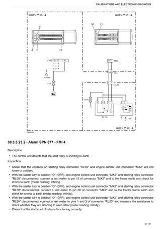
- Calibrations and electronic diagnosis
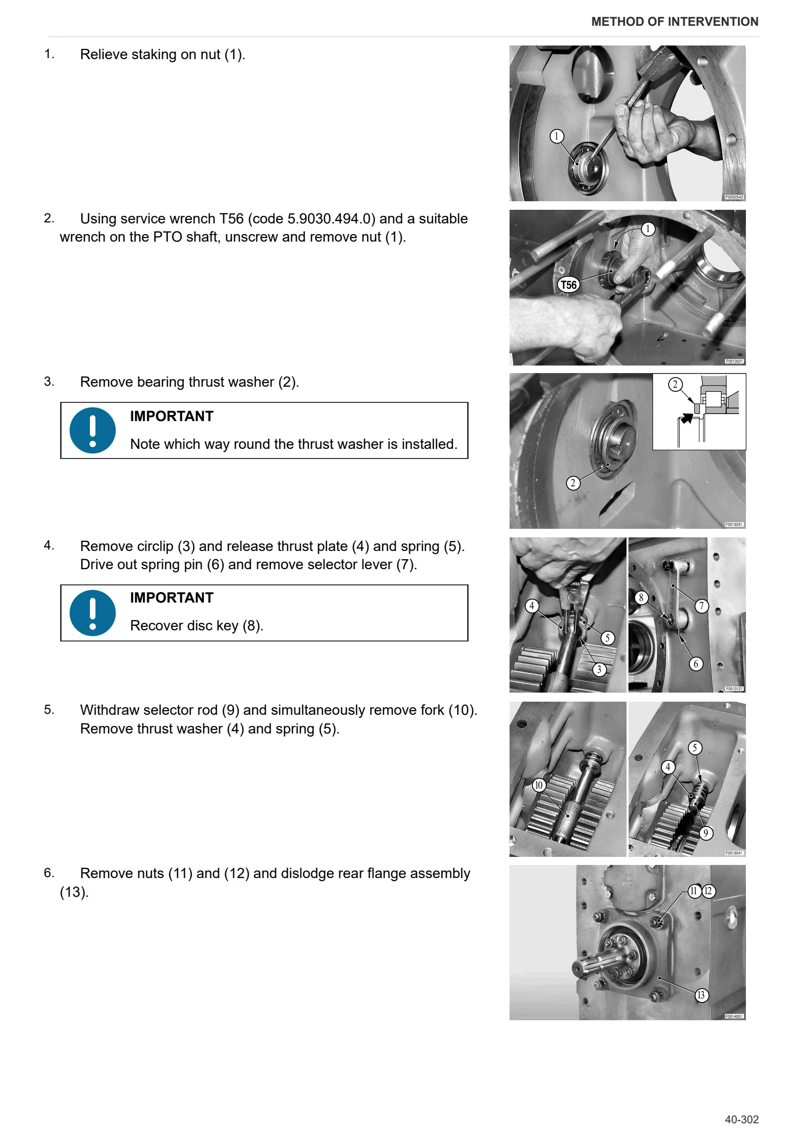
- Method of intervention
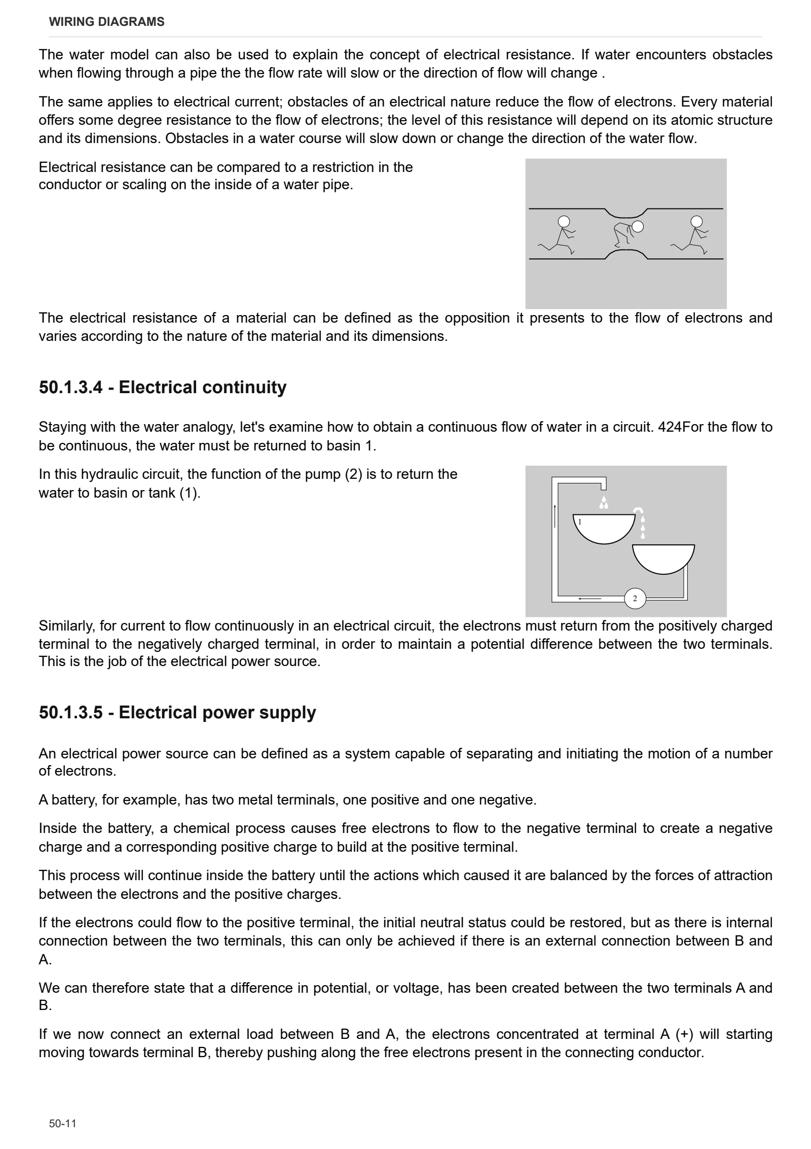
- Wiring diagrams
- Service Info
Document details
- Brand: DEUTZ FAHR
- Family: Agrotron L
- Model: AGROTRON L 720
- Starting serial number: ZKDJ2502W0TD01001
- Document type: Workshop Manual
- Language: English
- Pages: 1,549
- File size: 171.94 MiB
- Format: Digital PDF download
Compatibility
Before purchasing, verify that your machine model and reference code match DEUTZ FAHR AGROTRON L 720 → ZKDJ2502W0TD01001.
Complete table of contents
Introduction
- Tightening Torques
- Units of measurement and conversion factors
Safety
Preface
- Important notes concerning safety
Important safety information
- Recognising hazards
- Indications for persons in contact with the tractor
Safety rules
- Risks during tractor preparation
- Risks during maintenance
- Work on machine systems
- Special disassembly/assembly/inspection procedures
Safety pictograms
- Replacing safety pictograms
Environmental risks
- Hazards associated with the operating environment
Technical characteristics
Engine
- Engine 2013 components
- Pumps
- Injector type identification
- Engine monobloc technical data
- Pumps
- Injector type identification
- Crankshaft technical data
Transmission
- Main clutch
- POWER SHIFT Transmission
- H-M-L unit
- Intermediate gearbox
- Rear gearbox
- Rear PTO
Rear axle
- Rear axle
Front axle
- Front axle
Hydraulic system
- Hydraulic system
- Oil level maintenance pump
- Variable displacement pump
- Boost pump
- Hydraulic pump
- Load sensing valve, pressure cut-off valve
- Power steering valve
- Hydraulic front axle suspension
- Remote control valve
- Services control valve
- Main clutch control valve
- Power Shift control valve
- Range gearbox control valve
- Braking system
- Trailer braking valve – ITALY version
- Trailer braking valve – EXPORT version
Rear lift
- Rear lift
Calibrations and electronic diagnosis
Diagnostic tool screens
- Electronic system
- CANBUS System
- Engine control unit – Deutz EMR3
- HPSA control unit
- Transmission safety devices control unit
- Instrument panel
- Multifunction armrest
Commissioning and calibrating the tractor
- Introduction to commissioning the tractor
- Renewal of the engine control unit – Introduction
- Renewal of the engine control unit – Reading and saving DATASET
- Renewal of the engine control unit – Programming the control unit with DATASET
- HLHP control unit – Calibration of the accelerator pedal
- HLHP control unit – Calibration of the hand throttle lever
- Renewal of the armrest control unit – Introduction
- Renewal of the armrest control unit – Initialisation
- Renewal of the armrest control unit – Calibration of the accelerator pedal
- Renewal of the armrest control unit – Calibration of the clutch pedal
- Renewal of the armrest control unit – Calibration of the hand throttle
- Renewal of the armrest control unit – Entering the tractor operating hours
- Renewal of the armrest control unit – Configuration of the transmission type
- Renewal of the armrest control unit – Configuration of the maximum travel speed
- Renewal of the transmission control unit – Introduction
- Renewal of the transmission control unit – Configuration of the range sensor type
- Renewal of the transmission control unit – Preparation for clutch calibration
- Renewal of the transmission control unit – Automatic calibration of the clutches for gears I,II and III
- Renewal of the transmission control unit – Manual calibration of the clutches for gears I,II, III and M
- Renewal of the transmission control unit – Calibration of the range sensor
- Renewal of the transmission control unit – Input or editing of clutch calibration values
- Renewal of the safety devices control unit – Introduction
- Renewal of the safety devices control unit – Calibration of the clutch pedal sensor
- Renewal of the instrument panel – Introduction
- Renewal of the instrument panel – Configuration of the instrument panel
- Renewal of the HPSA control unit – Introduction
- Renewal of the HPSA control unit – Initialisation of the HPSA control unit
- Renewal of the HPSA control unit – Calibration of the lift position sensor
- Renewal of the HPSA control unit – Calibration of the steering angle sensor
- Renewal of the HPSA control unit – Configuration of the front PTO
- Renewal of the HPSA control unit – Configuration of the front axle suspension
- Renewal of the HPSA control unit – Configuration of the engine type
ECU alarms
- List of alarms displayed on the instrument panel
- List of alarms displayed on the ART
Engine alarms
- Engine ECU alarms – ART code SPN 91
- Engine ECU alarms – ART code SPN 94
- Engine ECU alarms – ART code SPN 97
- Engine ECU alarms – ART code SPN 100
- Engine ECU alarms – ART code SPN 102
- Engine ECU alarms – ART code SPN 105
- Engine ECU alarms – ART code SPN 108
- Engine ECU alarms – ART code SPN 110
- Engine ECU alarms – ART code SPN 157
- Engine ECU alarms – ART code SPN 158
- Engine ECU alarms – ART code SPN 168
- Engine ECU alarms – ART code SPN 190
- Engine ECU alarms – ART code SPN 563
- Engine ECU alarms – ART code SPN 630
- Engine ECU alarms – ART code SPN 639
- Engine ECU alarms – ART code SPN 651
- Engine ECU alarms – ART code SPN 652
- Engine ECU alarms – ART code SPN 653
- Engine ECU alarms – ART code SPN 654
- Engine ECU alarms – ART code SPN 655
- Engine ECU alarms – ART code SPN 656
- Engine ECU alarms – ART code SPN 676
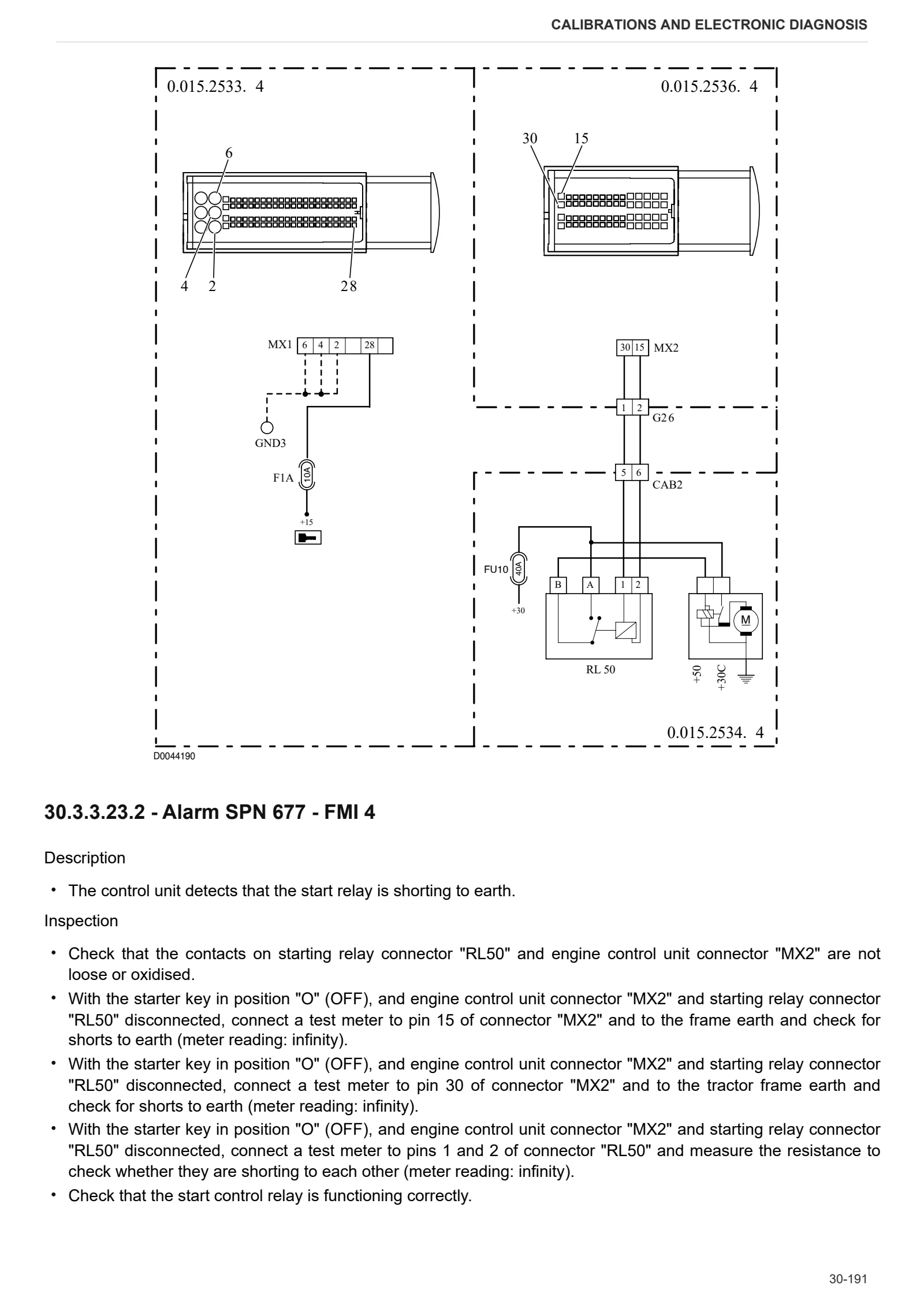
- Engine ECU alarms – ART code SPN 677
- Engine ECU alarms – ART code SPN 729
- Engine ECU alarms – ART code SPN 898
- Engine ECU alarms – ART code SPN 1079
- Engine ECU alarms – ART code SPN 1080
- Engine ECU alarms – ART code SPN 1235
- Engine ECU alarms – ART code SPN 2634
- Engine ECU alarms – ART code SPN 523240
- Engine ECU alarms – ART code SPN 523350
- Engine ECU alarms – ART code SPN 523351
- Engine ECU alarms – ART code SPN 523352
- Engine ECU alarms – ART code SPN 523353
- Engine ECU alarms – ART code SPN 523354
- Engine ECU alarms – ART code SPN 523355
- Engine ECU alarms – ART code SPN 523420
- Engine ECU alarms – ART code SPN 523470
- Engine ECU alarms – ART code SPN 523490
- Engine ECU alarms – ART code SPN 523550
- Engine ECU alarms – ART code SPN 523600
- Engine ECU alarms – ART code SPN 523601
- Engine ECU alarms – ART code SPN 523612
- Engine ECU alarms – ART code SPN 523613
- Engine ECU alarms – ART code SPN 523615
- Engine ECU alarms – ART code SPN 523617
Transmission alarms
- Transmission control unit alarms – ART code Config. error
- Transmission control unit alarms – ART code MainPres. K.O.
- Transmission control unit alarms – ART code Wheels Sens. Err.
- Transmission control unit alarms – ART code S.C. SV 1 (L)
- Transmission control unit alarms – ART code S.C. SV 2 (L)
- Transmission control unit alarms – ART code S.C. SV 3 (L)
- Transmission control unit alarms – ART code S.C. SV (L)
- Transmission control unit alarms – ART code S.C. SV M (L)
- Transmission control unit alarms – ART code S.C. SV H (L)
- Transmission control unit alarms – ART code S.C. SV <- (L)
- Transmission control unit alarms – ART code S.C. SV -> (L)
- Transmission control unit alarms – ART code S.C. SV MR (L)
- Transmission control unit alarms – ART code S.C. SV HR (L)
- Transmission control unit alarms – ART code O.C. SV1
- Transmission control unit alarms – ART code O.C. SV2
- Transmission control unit alarms – ART code O.C. SV3
- Transmission control unit alarms – ART code O.C. SVL
- Transmission control unit alarms – ART code O.C. SV M
- Transmission control unit alarms – ART code O.C. SVH
- Transmission control unit alarms – ART code O.C. SV <-
- Transmission control unit alarms – ART code O.C. SV ->
- Transmission control unit alarms – ART code O.C. SV MR
- Transmission control unit alarms – ART code O.C. SV HR
- Transmission control unit alarms – ART code ART CLUTCH 1 NOT CALIBRATED
- Transmission control unit alarms – ART code ART CLUTCH 2 NOT CALIBRATED
- Transmission control unit alarms – ART code ART CLUTCH 3 NOT CALIBRATED
- Transmission control unit alarms – ART code Cltch. SVp. Always ON
- Transmission control unit alarms – ART code Cltch. SVp OC Err.
- Transmission control unit alarms – ART code SVp. Always ON
- Transmission control unit alarms – ART code SVp. OC Err.
- Transmission control unit alarms – ART code PED_CALIB_SAFETY
- Transmission control unit alarms – ART code Seat fault
- Transmission control unit alarms – ART code SAF. ECU FAULT
- Transmission control unit alarms – ART code Clutch Ped.fault
- Transmission control unit alarms – ART code 5V power K.O.
- Transmission control unit alarms – ART code 6V8 power K.O.
- Transmission control unit alarms – ART code Service Pres. Err.
- Transmission control unit alarms – ART code Clutch Pres. Err.
- Transmission control unit alarms – ART code Direct. Pres. Err.
- Transmission control unit alarms – ART code S.C. Range. OC.
- Transmission control unit alarms – ART code O.C. Range. OC.
- Transmission control unit alarms – ART code OilT>130 degrees
- Transmission control unit alarms – ART code Range Sens. Disc.
- Transmission control unit alarms – ART code Range Sens. K.O.
- Transmission control unit alarms – ART code Range Neutral Err.
- Transmission control unit alarms – ART code S.C. SV1 (H)
- Transmission control unit alarms – ART code S.C. SV2 (H)
- Transmission control unit alarms – ART code S.C. SV3 (H)
- Transmission control unit alarms – ART code S.C. SVL (H)
- Transmission control unit alarms – ART code S.C. SVM (H)
- Transmission control unit alarms – ART code S.C. SVH (H)
- Transmission control unit alarms – ART code S.C. SV <- (H)
- Transmission control unit alarms – ART code S.C. SV -> (H)
- Transmission control unit alarms – ART code S.C. SV MR (H)
- Transmission control unit alarms – ART code S.C. SV HR (H)
- Transmission control unit alarms – ART code SV1 Control/Status
- Transmission control unit alarms – ART code SV2 Control/Status
- Transmission control unit alarms – ART code SV3 Control/Status
- Transmission control unit alarms – ART code SVL Control/Status
- Transmission control unit alarms – ART code SVM Control/Status
- Transmission control unit alarms – ART code SVH Control/Status
- Transmission control unit alarms – ART code SV <- Control/Status
- Transmission control unit alarms – ART code SV -> Control/Status
- Transmission control unit alarms – ART code EV MR Control/Status
- Transmission control unit alarms – ART code SV HR Control/Status
- Transmission control unit alarms – ART code SV1 Control/Curr.
- Transmission control unit alarms – ART code EV2 Control/Curr.
- Transmission control unit alarms – ART code SV3 Control/Curr.
- Transmission control unit alarms – ART code SVL Control/Curr.
- Transmission control unit alarms – ART code SVM Control/Curr.
- Transmission control unit alarms – ART code SVH Control/Curr.
- Transmission control unit alarms – ART code SV <- Control/Curr.
- Transmission control unit alarms – ART code SV -> Control/Curr.
- Transmission control unit alarms – ART code SV MR Control/Curr.
- Transmission control unit alarms – ART code SV HR Control/Curr.
- Transmission control unit alarms – ART code CLTCH 1 COEFF K.O.
- Transmission control unit alarms – ART code CLTCH 2 COEFF K.O.
- Transmission control unit alarms – ART code CLTCH 3 COEFF K.O.
- Transmission control unit alarms – ART code EEPROM SYSTEM
- Transmission ECU alarms – ART code EEPROM POWER
- Transmission control unit alarms – ART code Error Watchdog
- Transmission control unit alarms – ART code Err->I<-Signal
- Transmission control unit alarms – ART code Err+/-Signal
- Transmission control unit alarms – ART code Cltch.Sens.Fault
- Transmission control unit alarms – ART code CAN T.O. CCMsg1
- Transmission control unit alarms – ART code CAN T.O. ECMsg1
- Transmission control unit alarms – ART code CAN T.O. ICMsg1
Armrest alarms
- Armrest alarms – ART code CLTCH.PED.AL.
- Armrest alarms – ART code Hand Throt.Al
- Armrest alarms – ART code Acc. Ped. Al.
- Armrest alarms – ART code EEPROM CHECK TYRE
- Armrest alarms – ART code CAN T.O. ECMSG2
- Armrest alarms – ART code CAN T.O. INSTRUMENT
- Armrest alarms – ART code CAN T.O. REAR LIFT
- Armrest alarms – ART code CAN T.O. GEARBOX
HPSA alarms
- HPSA control unit alarms -ART code SPN 158
- HPSA control unit alarms -ART code SPN 540
- HPSA control unit alarms -ART code SPN 541
- HPSA control unit alarms -ART code SPN 550
- HPSA control unit alarms -ART code SPN 551
- HPSA control unit alarms -ART code SPN 552
- HPSA control unit alarms – ART code SPN 560
- HPSA control unit alarms – ART code SPN 602
- HPSA control unit alarms – ART code SPN 603
- HPSA control unit alarms – ART code SPN 620
- HPSA control unit alarms – ART code SPN 621
- HPSA control unit alarms – ART code SPN 622
- HPSA control unit alarms – ART code SPN 623
- HPSA control unit alarms – ART code SPN 629
- HPSA control unit alarms – ART code SPN 630
- HPSA control unit alarms – ART code SPN 631
- HPSA control unit alarms – ART code SPN 632
- HPSA control unit alarms – ART code SPN 633
- HPSA control unit alarms – ART code SPN 653
- HPSA control unit alarms – ART code SPN 654
- HPSA control unit alarms – ART code SPN 655
- HPSA control unit alarms – ART code SPN 656
- HPSA control unit alarms – ART code SPN 661
Canbus alarms
- CANBUS alarms – introduction
- CANBUS alarms – alarms table
- CANBUS alarms – Case 1 analysis
- CANBUS alarms – Case 2 analysis
- CANBUS alarms – Case 3 analysis
- CANBUS alarms – Case 4 analysis
- CANBUS alarms – Case 5 analysis
- CANBUS alarms – Case 6 analysis
- CANBUS alarms – Case 7 analysis
- CANBUS alarms – Case 8 analysis
- CANBUS alarms – Case 9 analysis
Electrohydraulic control valve alarms
- List of electrohydraulic control valve alarms
Method of intervention
B0 – Engine
- Engine – Separation from the transmission
- Engine
- Alternator, fuel pump, water pump and fan drivebelt
- Air conditioning compressor drivebelt
- Tensioning the compressor drivebelt
- Removal and refitting of the crankcase breather
- Renewal of the front crankshaft oil seal (opposite end to flywheel)
- Installation/removal of the front crankshaft wear sleeve (opposite end to flywheel)
- Removal and refitting of the front cover (opposite end to flywheel)
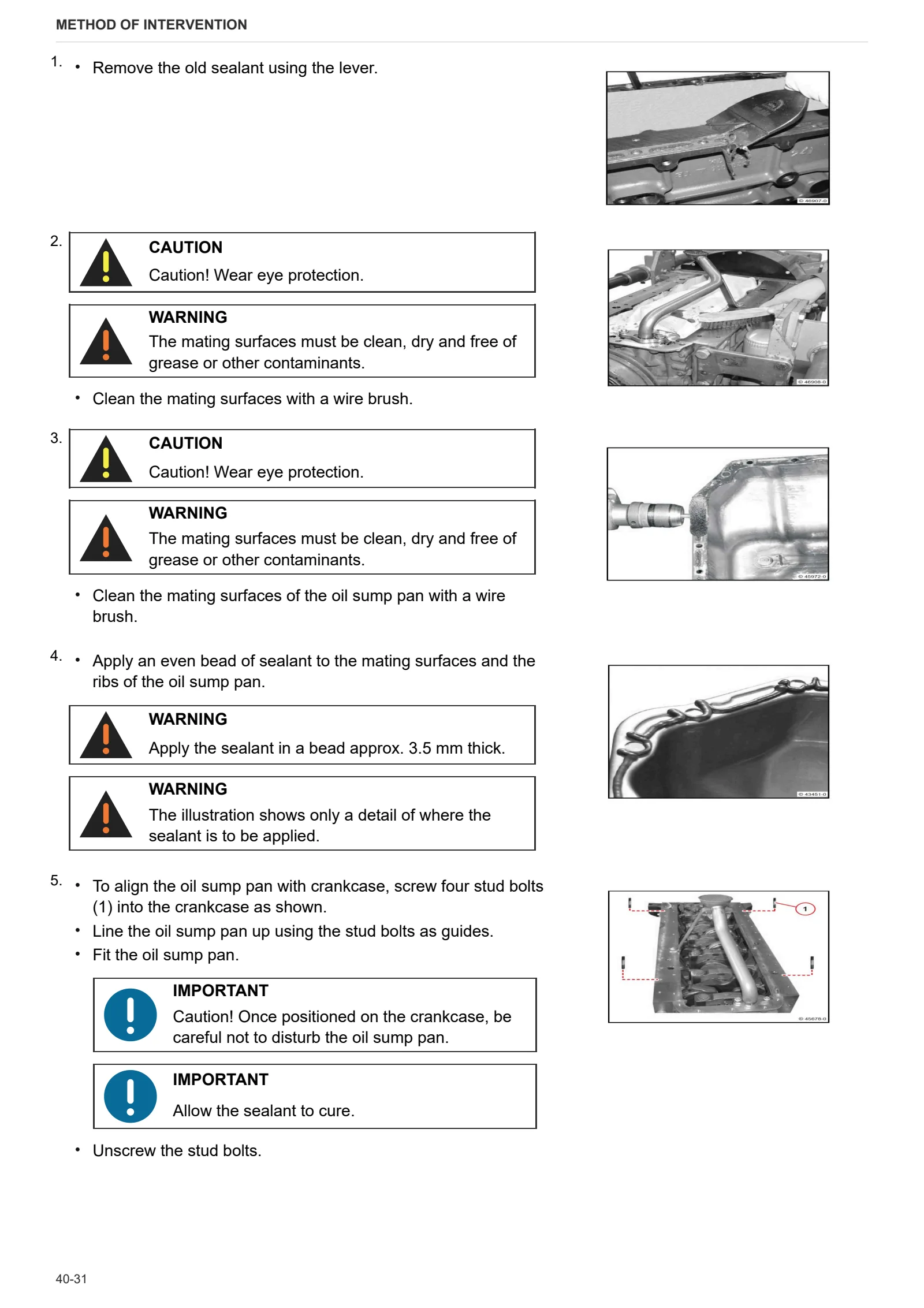
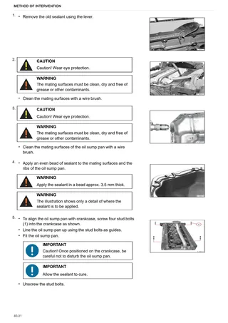
- Removal and refitting of the oil sump pan.
- Removal and refitting of the V-belt and pulley
- Removal and refitting of the torsional vibration damper
- Removal and refitting of the flywheel
- Compression test
- Removal and refitting of the cylinder head cover
- Renewal of the rear crankshaft oil seal (flywheel end)
- Valve clearance adjustment (with the exhaust gas recirculation module installed).
- Valve clearance adjustment (with the exhaust gas recirculation module absent or removed).
- Removal and refitting of the rocker arms and pedestals
- Removal and refitting of the oil cooler
- Removal and refitting of the lube oil cooler housing
- Removal and refitting of the oil pickup pipe
- Removal and refitting of the fuel control unit
- Removal and refitting of the high-pressure pump (installation position A)
- Removal and refitting of the high-pressure pump (installation position B)
- Removal and refitting of the injectors
- Removal and refitting of the fuel lift pump
- Removal and refitting of the common rail
- Removal and refitting of the pressure limiting valve
- Removal and refitting of the rail pressure sensor
- Removal and refitting of the charge air duct
- Removal and refitting of the water pump
- Removal and refitting of the fuel pressure sensor
- Removal and refitting of the belt tensioner
- Removal and refitting of the fan drive system
- Removal and refitting of the fan support (fan driven by ribbed V-belt)
- Removal and refitting of the exhaust manifold
- Removal and refitting of the turbocharger
C0 – Engine accessories
- Changing the coolant and flushing the circuit
- Radiator
- Expansion tank
- Fan
- Intercooler
- Air cleaner assembly
- Fuel tank
- Auxiliary fuel tank
- Starter motor
- Silencer
- Intermediate manifold
- Exhaust pipe
- Air compressor
- Removal and refitting of the fuel filter head.
- Removal and refitting of the thermostat
- Testing the thermostat (after removal)
- Removal and refitting of the thermostat housing
- Removal and refitting of the alternator (with drivebelt)
- Removal and refitting of the starter motor
- Removal and refitting of the engine wiring loom
- Removal and refitting of the camshaft speed sensor
- Removal and refitting of the crankshaft speed sensor
- Removal and refitting of the intake air pressure/temperature sender
- Removal and refitting of the oil pressure switch
- Removal and refitting of the coolant temperature sender
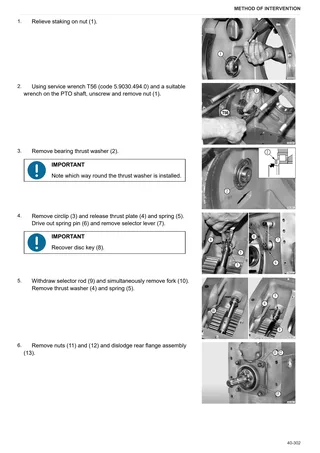
- Removal and refitting of the rotation device
- Removal and refitting of the torsional vibration damper
- Removal and refitting of the heater
- Removal and refitting of the glowplugs
D0 – Transmission
- Changing the transmission oil
- Main clutch control unit
- Main clutch
- Disassembly of main clutch control assembly
- Disassembly of main clutch
- HML unit and main clutch
- HML unit and main clutch – Separation from the transmission
- H clutch assembly
- Disassembly of the H clutch assembly
- L-M clutches assembly
- Planet carrier
- Disassembly of the planet carrier
- POWERSHIFT Control valve
- Disassembly of POWERSHIFT control unit
- Torsional spring plate
- Disassembly of the secondary shaft
- Front gearbox
- Rear gearbox
- Front gearbox cover
- Range gear control cover
- Range gear control unit
- Disassembly of the range reduction unit control assembly
- Range gear and creeper selector assembly
- Shuttle control unit
- Disassembly of the shuttle control unit
- Shuttle control unit
- Adjustment of the differential – bevel gear pair
- Disassembly of the rear pinion
- Adjustment of pinion and crown wheel backlash
- Range driving gear
- Disassembly of the range driving gear
- Range driving gear
- Creeper planetary reduction unit
- Disassembly of the creeper planetary gear unit
- PTO clutch
- Disassembly of the PTO clutch.
- PTO output shaft
- PTO output shaft
- Parking brake
- Disassembly of the parking brake
- 4WD engagement device
- Disassembly of the 4WD engagement device
E0 – Rear axle
- RH/LH rear axle
- Disassembly of LH/RH rear axle
- Disassembly of the planet carrier
- Rear differential
- Disassembly of the rear differential
- Brake assembly and rear axle brake discs
- Disassembly of the rear axle brake assembly
- Adjustment of the brake assemblies
- Parking brake discs
F0 – Front axle
- Front support
- Front support and front axle
- Front axle pivot bushings
- Front axle and swinging support
- Adjustment of the play in the axle pivot bearings
- Steering cylinders
- Steering knuckle housing and half-shaft
- Adjustment of the steering knuckle bearings preload
- Differential unit – Version without front axle suspension
- Disassembly of the differential locking device
- Bevel drive – Version without front suspension
- Pinion positioning and preload adjustment
- Disassembly of the differential
- Adjustment of the differential preload
- 4WD shaft – Version with front axle suspension
- 4WD shaft – Version without front axle suspension
- Renewal of front axle bevel pinion oil seal – Version without front axle suspension
- Renewal of front axle bevel pinion oil seal – Version with front axle suspension
- Planetary reduction gear
- Disassembly of the planetary reduction gear
- Front brake discs
- Disassembly of the front axle brake piston
G0 – Bodywork – Cab – Platform
- Cab
- Front hood and side panels
- Reservoir-battery support
- Rear cab support
- Cab height adjustment valve
- Adjustable fenders
- Windscreen wiper motors
- Right-hand console
- Left-hand console
- Instrument panel
- Centre console
- Seat and multifunction armrest
- Air conditioning system
- Air conditioning compressor
- Condenser
- Receiver-drier
- Air conditioning evaporator
- Heater valve
- Heater matrix
- Air conditioner RH fan
- Air conditioner LH fan
- Air conditioner fans support
- Clutch pedal
- Adjustment of the brake pedals
- Brake master cylinders
- Parking brake cable
- Steering wheel
- Remote valve control cables
- Remote valve control levers
- Remote valve control levers – Version with cross-gate joystick
H0 – Hydraulic system
- Pump for hydraulic lift and remote control valve
- Transfer pump
- Complete pumps assembly
- Disassembly of the pumps control assembly
- Functionality test of auxiliary services pump
- Power steering valve
- Power steering disassembly
- Power steering – Complete assembly – Checks and calibration
- Power steering pump
- Gearbox oil and fuel cooler
- Front lift valve and accumulators assembly
- Rear remote control valve
- Disassembly of the rear remote control valve – 6-way version
- Disassembly of the rear remote control valve – 8-way version
- Disassembly of the rear remote control valve – 8-way version with electrically operated valve
- Braking circuit
- 1-way trailer air braking valve – Export D version
- 2-way trailer air braking valve
- Compressed air circuit supply pressure control valve
- Trailer parking brake control solenoid valve
L0 – Electrical system
- Alternator
- Fuse box
- Engine ECU
- Transmission ECU – Lift ECU – Safety devices ECU
- Clutch pedal potentiometer
- Accelerator potentiometer
- Front suspension position sensor
- Front axle suspension position sensor
- Steering angle sensor
- Shuttle control
M0 – Front PTO
- Front PTO – complete assembly
- PTO assembly.
- Pump assembly
- Clutch-brake assembly
- Front PTO flexible coupling
- Solenoid valve assembly
N0 – Front lift
- Front lift cylinders
R0 – Rear lift
- Lift – Complete assembly
- Disassembly of the lift – complete assembly
- Auxiliary lift cylinders
- Disassembly of the auxiliary lift cylinders
- Draft sensor
S0 – Wheels
- Front wheels
- Rear wheels
Wiring diagrams
Introduction
- Structure of the unit
- Basic electronics for mechanics (1/2)
- Basic electronics for mechanics (2/2)
- Electrical and electronic components (1/2)
- Electrical and electronic components (2/2)
- Wiring and components index
Components
- Components
Systems
- Earthing points
- Starting
- Preheating
- Electronic engine control
- Steering column lights switch
- Instrument panel
- Worklights
- Wipers
- Radio – CB
- Air conditioning – heater fans
- Cab accessories
- Transmission
- Front and rear PTO
- Outlet socket
- CAN BUS
- Brakes
- Trailer brakes – Italy version
- Trailer brakes – EXPORT D version
- Front axle suspension
- Electronic control valves
- ASM/SBA – 4WD – differential
- Electronic lift
Wiring harnesses
- Battery leads wiring – 0.015.2535.4
- Battery wiring connector positions
- Engine wiring – 0421.4226 – 0421.4895
- Front wiring – 0.015.2534.4
- Positions of front wiring connectors
- Steering angle sensor wiring – 0.010.8707.4/10
- Positions of steering angle sensor wiring connectors
- Front axle suspension wiring loom – 0.013.4463.4
- Positions of front axle suspension wiring connectors
- Front lights wiring – 0.015.4030.4/10
- Positions of front light wiring connectors
- Engine interface wiring – 0.015.2536.4
- Engine interface connector positions
- Transmission wiring – 0.013.4461.4/10
- Positions of transmission wiring connectors
- Central wiring – 0.015.2532.4
- Positions of central wiring connectors
- Rear wiring – 0.013.4462.4/10
- Positions of rear wiring connectors
- Subframe wiring – 0.015.2533.4
- Positions of subframe wiring connectors
- Lights selector switch wiring – 0.014.0007.4
- Positions of lights selector switch wiring connectors
- Compressed air pressure gauge wiring – 0.011.7032.4
- Positions of compressed air pressure gauge wiring connectors
- Air conditioning wiring – 0.900.0783.8
- Positions of A/C wiring connectors
- Roof wiring – 0.010.8700.4/30
- Roof wiring connector positions
- Cab lower headlights wiring loom – 0441.1923.4
- Positions of connectors for lower front lights wiring on cab
- Coolant tank wiring – 0.011.6007.3
- Positions of coolant tank wiring connectors
- Air braking wiring (EXPORT D) – 0.011.9430.4
- Positions of air braking wiring connectors (EXPORT D)
- Rear lights wiring – 0.010.8711.4/30
- Position of rear lights wiring connectors
- Rotating beacon wiring – 0.011.3824.4/10
- Positions of rotary beacon wiring connectors
Service Info
A0 – TRACTOR
- Diagnostics 2026 subscription
- After-sales 2026 subscription
- SERVICE NEWS RESEARCH GUIDE
- Diagnostics 2025 subscription
- After-sales 2025 subscription
- Diagnostics 2023 subscription
- Diagnostics 2024 subscription
- Diagnostics 2022 subscription
- Diagnostics 2021 subscription
- Technical Documentation DVD 06/2009
- Technical Documentation DVD 07/2008
- Nameplate
- DEUTZ-FAHR LUBRICANTS: Lubricant oils and coolant fluids
- SDF LUBRICANTS: Lubricant oils and coolant fluids
- After-sales 2024 subscription
- After-sales 2023 subscription
- After-sales 2022 subscription
- After-sales 2021 subscription
- After-sales 2019 subscription
- SDF Parts and SDF Service DVV 04/2014, version 26
- Technical Documentation DVD 03/2010
- New function: Download PDF manuals
- Diagnostics – 2020 subscription
- After-sales – 2020 subscription
- After-sales – 2018 subscription
- Service and Spare Parts – 2017 Subscription
- SDF Parts and SDF Service DVDs 05/2014 version 25
- SDF Parts and SDF Service DVDs 03/2013 version 24
B0 – ENGINE
- Flushing the lubrication circuit
- Deutz AG engine oil specifications
- SerDia 2010 updating license file
- Modifications to Fuel Control Unit (FCU) – DEUTZ TCD 2012/2013 Euro 3 engines
C0 – ENGINE ACCESSORIES
- Diagnostic protocol – AdBlue – Float level unit
- Filter and prefilter tool p/n 5.9035.865.0
- Additive for diesel fuel
D0 – TRANSMISSION
- Cracks in rear gearbox housing
F0 – FRONT AXLE
- Check the front axle steering knuckles for wear
- Steering behavior check procedure
G0 – BODYWORK – CAB
- Air conditioning system recharging
H0 – HYDRAULIC AND PNEUMATIC SYSTEM|
- Hydraulic CUNA trailer braking kit (ITALY)
- Single connection hydraulic braking kit availability update – only for EUROPEAN market
- Resonator failure
- L0 – ELECTRIC AL SYSTEM