Document overview
Workshop Manual PDF for DEUTZ FAHR AGROPLUS F 75 → D10F704WVT2E03001, Agroplus F family. Document language: English; 1,208 pages.
The corresponding English table of contents contains 52 sections and 433 individual topics.
Main sections included
- Introduction
- Safety
- Technical characteristics
- Calibrations and electronic diagnosis
- Method of intervention
- Wiring diagrams
- Service Info
Document details
- Brand: DEUTZ FAHR
- Family: Agroplus F
- Model: AGROPLUS F 75
- Starting serial number: D10F704WVT2E03001
- Document type: Workshop Manual
- Language: English
- Pages: 1,208
- File size: 221.50 MiB
- Format: Digital PDF download
Compatibility
Before purchasing, verify that your machine model and reference code match DEUTZ FAHR AGROPLUS F 75 → D10F704WVT2E03001.
Complete table of contents
Introduction
- Introduction – Engines
- Identification of the engine type and serial number position, Europe version
- Identification of the engine type and serial number position, EPA version
- Injection pump type identification
- Injector type identification
- Tightening Torques
- Units of measurement and conversion factors
Safety
Preface
- Important notes concerning safety
Important safety information
- Recognising hazards
- Indications for persons in contact with the tractor
Safety rules
- Risks during tractor preparation
- Risks during maintenance
- Work on machine systems
- Special disassembly/assembly/inspection procedures
Safety pictograms
- Replacing safety pictograms
Environmental risks
- Hazards associated with the operating environment
Technical characteristics
Engine
- Engine block technical data – cylinders
- Crankshaft technical data
- Crankshaft technical data
- Crankshaft technical data
- Piston technical data – Piston rings
- Piston technical data – Piston rings
- Piston technical data – Piston rings
- Piston technical data – Piston rings
- Connecting rod technical data
- Connecting rod technical data
- Camshaft technical data – static advance of 13°
- Camshaft technical data – static advance of 16°
- Timing gears technical data
- Counter-rotating weights technical data
- Technical data and dimensions of valves – valve springs
- Technical data and dimensions of cylinder heads – valve guides – valve seats
- Technical data and dimensions of rocker arms – rocker shafts – tappets
- Engine injector technical data (aspirated versions)
- Engine injector technical data (with turbocharger)
- Injectors technical data (turbo-intercooler engines)
Transmission
- Transmission
- Rear PTO
Front axle
- Front axle
Bodywork – Cab – Platform
- Air conditioning system
Hydraulic system
- Hydraulic system diagrams
- Steering and lift circuit gear pumps diagrams
- Power steering valve
- Auxiliary services directional control valve
- Hydraulic lift directional control valve
- Trailer braking valve
- Services solenoid valve assembly
- HML solenoid valve assembly
- 3-point linkage hydraulic control valve
Front PTO
- Front PTO
Front lift
- Front lift
Calibrations and electronic diagnosis
Diagnostic tools
SDF Analyser
- SDF Analyser
Diagnostic tool screens
- Introduction to the tractor’s electronic system
Commissioning and calibrating the tractor
- Putting the tractor into service
ECU alarms
Engine alarms
- Engine alarms
- Engine ECU alarms – ART code “Overspeed “
- Engine ECU alarms – ART code “Actuator O.C.”
- Engine ECU alarms – ART code “Actuator S.C.”
- Engine ECU alarms – ART code “Accel.Pedal O.C.”
- Engine ECU alarms – ART code “Accel.Pedal S.C.”
- Engine ECU alarms – ART code “RPM.Sensor O.C.”
- Engine ECU alarms – ART code “Interm.RPM.Sensor”
- Engine ECU alarms – ART code “EEPROM faulty”
- Engine ECU alarms – ART code “Speed Sensor O.C.”
- Engine ECU alarms – ART code “Interm.Speed Sensor”
- Engine ECU alarms – ART code “Hand throttle O.C.”
- Engine ECU alarms – ART code “Hand throttle S.C.”
- Engine ECU alarms – ART code “HL PTO SV shutdown”
- Engine ECU alarms – ART code “REAR PTO SV O.C.”
- Engine ECU alarms – ART code “REAR PTO SV S.C.”
- Engine ECU alarms – ART code “SpeedSens.2 O.C.”
- Engine ECU alarms – ART code “SpeedSen.2 Inter.”
- Engine ECU alarms – ART code “Config.Error”
- Engine ECU alarms – ART code “SpeedSen.Log.Err.”
- Engine ECU alarms – ART code “FRONT PTO SV O.C.”
- Engine ECU alarms – ART code “FRONT PTO SV S.C.”
- Engine ECU alarms – ART code “FRONTPTObuttonfaulty”
- Engine ECU alarms – ART code “REARPTObuttonfaulty”
- Engine ECU alarms – ART code “General Alarm”
- Engine ECU alarms – ART code “Flash faulty”
- Engine ECU alarms – ART code “Temp.Sensor O.C.”
- Engine ECU alarms – ART code “Temp.Sensor S.C.”
- Engine ECU alarms – ART code “FRONTPTObulbBlown”
- Engine ECU alarms – ART code “REARPTObulbblown”
Hydraulic shuttle alarms
- Hydraulic shuttle alarms
- Hydraulic shuttle alarms – ART code “SVL status not ok”
- Hydraulic shuttle alarms – ART code “SVL short-circ.”
- Hydraulic shuttle alarms – ART code “SVL Open Circuit”
- Hydraulic shuttle alarms – ART code “RPM Sensor Open”
- Hydraulic shuttle alarms – ART code “Oil Tmp.Sns.Open”
- Hydraulic shuttle alarms – ART code “Oil Tmp.Sns. S.C.”
- Hydraulic shuttle alarms – ART code “TurnIndSwtch N.V.”
- Hydraulic shuttle alarms – ART code “PrxProp.Fault”
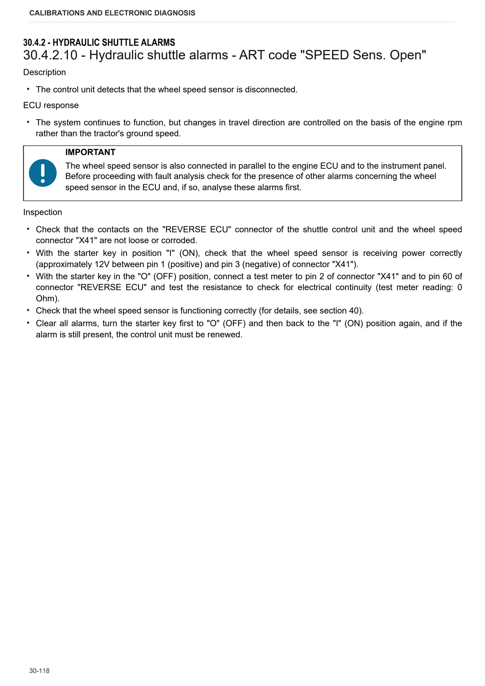
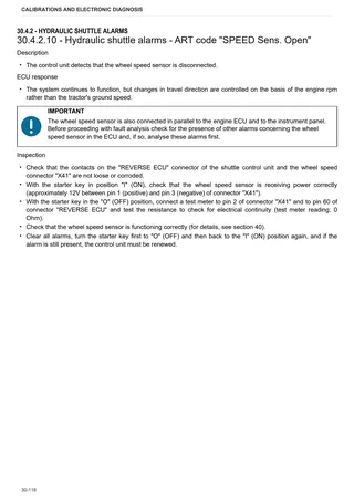
- Hydraulic shuttle alarms – ART code “SPEED Sens. Open”
- Hydraulic shuttle alarms – ART code “ClutchKey”
- Hydraulic shuttle alarms – ART code “SVH status not ok”
- Hydraulic shuttle alarms – ART code “SVH Short-circ.”
- Hydraulic shuttle alarms – ART code “SVH Open Circuit”
- Hydraulic shuttle alarms – ART code “REV Sens.Open”
- Hydraulic shuttle alarms – ART code “Open Pedal Pos.”
- Hydraulic shuttle alarms – ART code “Ped. Pos.N.V.”
- Hydraulic shuttle alarms – ART code “Ped.Pos.S.C./Open.C.”
- Hydraulic shuttle alarms – ART code “HML+ key pressed”
- Hydraulic shuttle alarms – ART code “HML+ key pressed”
- Hydraulic shuttle alarms – ART code “SVp status not ok”
- Hydraulic shuttle alarms – ART code “”B” Ped.Pos. Open”
- Hydraulic shuttle alarms – ART code “”B” Ped.Pos. S.C.”
- Hydraulic shuttle alarms – ART code “”B” Ped.Pos. xxxx”
- Hydraulic shuttle alarms – ART code “SVR status not ok”
- Hydraulic shuttle alarms – ART code “SVR short-circ.”
- Hydraulic shuttle alarms – ART code “SVR Open Circuit”
- Hydraulic shuttle alarms – ART code “SVP short-circ.”
- Hydraulic shuttle alarms – ART code “Opr.Amplif.Pwr.Sp.”
- Hydraulic shuttle alarms – ART code “ClutchSensorSupply”
- Hydraulic shuttle alarms – ART code “HML circuit S.C.”
- Hydraulic shuttle alarms – ART code “REVcirc. S.C.”
- Hydraulic shuttle alarms – ART code “HML St.N.V relay”
- Hydraulic shuttle alarms – ART code “REV St.N.V relay”
- Hydraulic shuttle alarms – ART code “REV Group Faulty”
- Hydraulic shuttle alarms – ART code “SVP Open Circuit”
- Hydraulic shuttle alarms – ART code “PrxServices missing”
- Hydraulic shuttle alarms – ART code “Prop.Pressure”
- Hydraulic shuttle alarms – ART code “E2PROM faulty”
- Hydraulic shuttle alarms – ART code “REV sensor S.C.”
- Hydraulic shuttle alarms – ART code “RPM sensor S.C.”
- Hydraulic shuttle alarms – ART code “Manoeuvre > 10km/h”
- Hydraulic shuttle alarms – ART code “REV Cltch. Slip.”
- Hydraulic shuttle alarms – ART code ” PrxProp.missing”
- Hydraulic shuttle alarms – ART code “HML St.N.V relay”
- Hydraulic shuttle alarms – ART code “REV St.N.V relay”
- Hydraulic shuttle alarms – ART code “Serious alarm”
- Hydraulic shuttle alarms – ART code “SV status not ok”
- Hydraulic shuttle alarms – ART code “SV short-circ.”
- Hydraulic shuttle alarms – ART code “SV open circ.”
- Hydraulic shuttle alarms – ART code “Seat Sensor KO”
- Hydraulic shuttle alarms – ART code “.PrxRHBrakesTrans.”
- Hydraulic shuttle alarms – ART code “LHBrakesPrxTrans.”
Instrument panel alarms
- Instrument panel alarms
- Instrument panel alarms – ART code 18
- Instrument panel alarms – ART code 19
- Instrument panel alarms – ART code 20
- Instrument panel alarms – ART code 21
Lift alarms
- Lift alarms
- Lift alarms – ART code “UPSV DISCONN.”
- Lift alarms – ART code “UPSV S.C.”
- Lift alarms – ART code “DWSV DISCONN.”
- Lift alarms – ART code “DWSV S.C.”
- Lift alarms – ART code “EPROM CHECK”
- Lift alarms – ART code “POS.SENS.S.C.”
- Lift alarms – ART code “POS.SENS.DIS.”
- Lift alarms – ART code “GEN.FAIL.CPU”
- Lift alarms – ART code “DRAFT SENS N.C.”
- Lift alarms – ART code “DRAFT SENS S.C.”
- Lift alarms – ART code “EEPROM CHECK”
- Lift alarms – ART code “NO V. SENSOR”
Method of intervention
B0 – Engine
- Engine – Separation from the transmission
- Engine – Removal and refitting
- Preliminary and final operations
- Final engine checks
- Checking engine block
- Crankshaft
- Crankshaft checks
- Flywheel checks
- Renewal of crankshaft rear oil seal
- Pistons and cylinder liners
- Pistons and rings check
- Cylinder liners check
- Check connecting rods – gudgeon pins – rod cap screws
- Camshaft
- Camshaft checks
- Timing gear checks
- Adjusting timing gears backlash
- Valve timing
- Counter-rotating weights
- Overhaul of counter-rotating weights assembly
- Counter-rotating weight checks
- Valves check
- Valve seats check
- Valves sealing check
- Valves adjustment
- Valve guides check and replacement
- Inspecting the rocker arms and rocker shafts
- Cylinder heads
- Valve springs check
- Heat exchanger removal
- Disassembly of the heat exchanger
- Lubrication pump
- Lubrication pump disassembly
- Oil sump
- INJECTION PUMPS, GOVERNOR AND FUEL SUPPLY
- Injection pump timing
- Injectors assembly
- Checking injectors protrusion – Renewal of copper bushes
- Injectors check
- Injection pumps control rod
- Overhaul of the mechanical governor (standard and with LDA valve)
- Overhaul of the mechanical governor gear
- Adjusting electronic actuator
- Installation of mechanical governor drive unit and electronic governor support
- Power adjustment data table
- Engine coolant pump
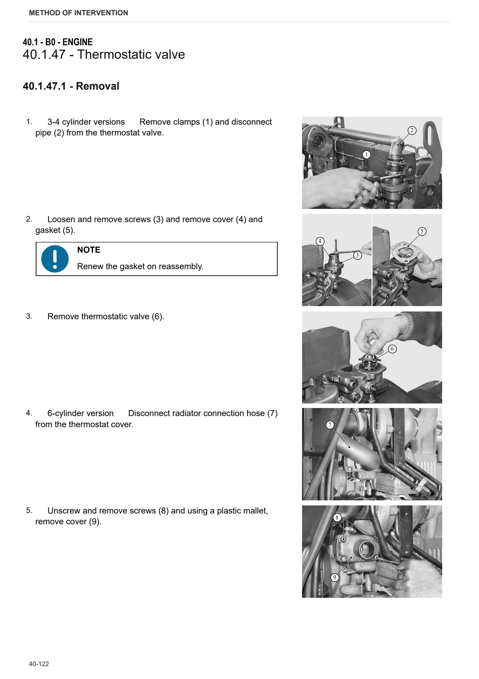
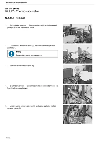
- Thermostatic valve
- Checking the thermostat valve
- Cooling and intake ducts
C0 – Engine accessories
- Changing the coolant and flushing the circuit
- Coolers
- Fuel tank
- Additional fuel tank
- Starter motor
D0 – Transmission
- Changing transmission oil
- Shuttle assembly – complete unit
- Disassembly of shuttle assembly
- Cover assembly
- Forward drive clutch unit
- Reverse drive clutch unit
- HML unit
- Clutch assembly
- Planet gear support unit – HML unit
- Gearbox input shaft – Version with HML
- Gearbox input shaft – Version without HML
- Torsional spring plate
- Primary shaft – Version with HML
- Primary shaft – Version without HML
- Disassembling secondary shaft – Version with range selector unit
- Secondary shaft – Version without HML
- Disassembly of gearbox and shuttle unit – Complete assy – Version with HML
- Disassembly of gearbox and shuttle unit – Complete assy – Version with HML
- Disassembly of gearbox and shuttle unit – Complete assy – Version without HML
- Disassembly of gearbox and shuttle unit – Complete unit – Version without HML
- Range and differential assembly – complete assembly
- Gearbox and shuttle unit – Separating from the transmission – Version with HML
- Gearbox and shuttle unit – Separating from the transmission – Version without HML
- Gearbox support and gear selector rods
- Range selector rod
- Underdrive control rod – Version with HML
- Sprocket
- Differential – Bevel gear pair
- Dual traction output shaft and groundspeed PTO
- PTO clutch
- PTO clutch disassembly.
- PTO pumps drive – Inner gear
- PTO output shaft (2 speed + ground speed)
- PTO output shaft. – 3-speed version
- Ground speed P.T.O. control shaft
- PTO final shaft.
- PTO output flange shaft, 2 speed version
- Hand brake
- Dual traction engagement device – Version without HML
- Disassembly of the four-wheel drive engagement device – Version without HML
E0 – Rear axle
- RH rear axle
- RH/LH rear axle – Version with normal axle
- LH rear axle
- Planet gear carrier
- Differential
- Removing rear differential
- Rear axle brake discs
- Rear axle brake piston
F0 – Front axle
- Front carrier
- 4WD front axle
- Adjusting front axle end float
- Steering cylinder
- Steering cylinders disassembly
- Steering knuckle housing and halfshaft
- Steering knuckle and halfshaft
- Pinion-differential assembly
- Differential lock device
- Differential lock device
- Bevel gear pair
- Adjustment of the pinion position and bearing preloading
- Differential
- 4WD shaft
- Final drive reduction unit
- Final drive reduction unit disassembly
- Front brake discs
- Front axle brake piston
G0 – Bodywork – Cab – Platform
- Cab
- Platform
- Front hoods
- Instrument panel
- Brake master cylinders
- Control levers – Version with mechanical lift
- Roll Over Protective Structures
H0 – Hydraulic system
- Pump for hydraulic lift and auxiliary services
- Power steering
- Pressure relief valve setting
- Power steering disassembly
- Power steering pump
- Rear auxiliary services directional control valve
- Hydraulic trailer braking valve
- Valve for trailer hydraulic braking – Export Version
- Services solenoid valve assembly
- Disassembling the ancillary solenoid valves
M0 – Front PTO
- PTO assembly.
- Clutch-brake assembly
- PTO shaft.
N0 – Front lift
- Front lift
- Front lift cylinders
- Disassembly of front lift cylinders
- Cylinder support
R0 – Rear lift
- Lift – Complete unit – Version with mechanical lift
- Lift disassembly – complete unit – Version with mechanical lift
- Lift unit – Complete assy – Version with electronic lift
- Lift disassembly – Complete unit – Version with electronic lift
- Lift cylinder – Version with mechanical lift
- Bushings – Version with mechanical lift
- Lift control distributor – Version with mechanical lift
- Disassembling the lift control cylinder – Version with mechanical lift
- Lift control valve – Version with electronic lift
- Mechanical draft sensor – Version with mechanical lift
- Mechanical draft sensor – Version with electronic lift
- Mechanical draft sensor disassembly – Version with mechanical lift
- Position sensor
- 3-point hitch
S0 – Wheels
- Front wheels
- Rear wheels
V0 – Ballast – towing hitches
- Towing hitch
Wiring diagrams
Introduction
- Structure of the unit
- Wiring and components index
Components
- Components
Systems
- Earthing points
- Starting and pre-heating
- Electronic engine control
- Lights – steering column switch unit – Version with cab
- Lights – Steering column switch unit – Version with platform
- Diagnostic accessories – Version with cab
- Diagnostic accessories – Version with platform
- Instrument panel
- Worklights -Version with cab
- Worklights – Version with platform
- Windscreen wipers
- Heating
- Air conditioning
- HML transmission
- Front and rear PTO
- Brakes
- Front control valve
- Electronic lift – Version with cab
- 3-point hitch
- CANBUS ELECTRONIC SYSTEM
Wiring harnesses
- Battery leads wiring – 0.010.6708.3/20
- Battery wiring connector positions
- Pre-heating and power supply wiring – tractor with 3-cylinder engine and cab – 0.013.8400.4/10
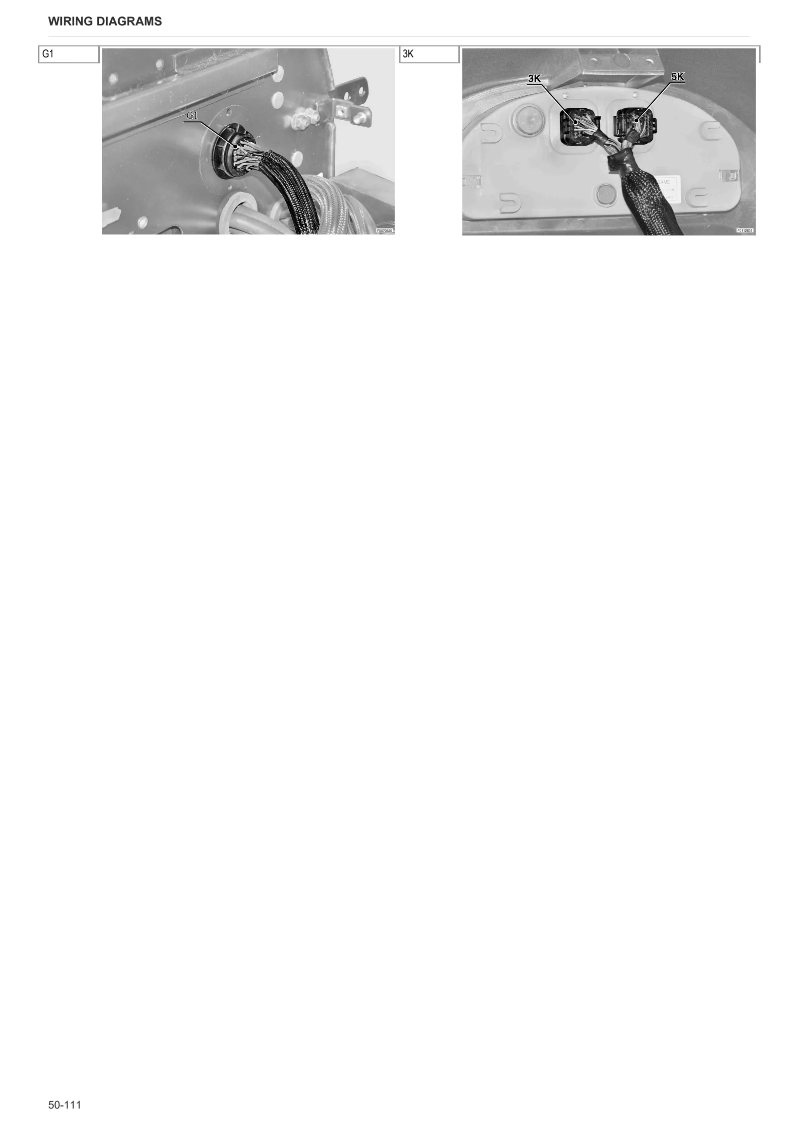
- Position of preheating and power supply wiring connectors – Version with 3-cylinders and cab
- Pre-heating and power supply wiring – tractor with 4-cylinder engine and cab – 0.013.8399.4/10
- Position of preheating and power supply wiring connectors – Version with 4-cylinders and cab
- Pre-heating and power supply wiring – tractor with 3-cylinder engine and platform – 0.013.8402.4
- Position of preheating and power supply wiring connectors – Version with 3-cylinders and platform
- Pre-heating and power supply wiring – tractor with 4-cylinder engine and platform – 0.013.8401.4
- Position of preheating and power supply wiring connectors – Version with 4-cylinders and platform
- Front control valve wiring – 0.014.4784.4
- Front P.T.O. wiring – 0.012.2756.3
- Front wiring loom – 3-cylinder version – 0.015.3157.4
- Position of front wiring connectors – Version with 3-cylinders
- Front wiring – 4-cylinder version – 0.015.3158.4
- Position of front wiring connectors – Version with 4-cylinders
- Central wiring loom – 0.015.3149.4/10
- Central wiring connector positions
- Electronic lift wiring – 0.011.2025.4/40
- 3-point linkage wiring – 0.012.0101.4
- Rear wiring – 0.015.3150.4
- Positions of rear wiring loom connectors
- Heating system wiring – 1.004.0880.0
- Position of heating system wiring connectors
- Air conditioning wiring – 5.059.010.0.0
- Position of air conditioner wiring loom connectors
- Air conditioning cooler fan wiring – 0.010.0099.3
- Position of air conditioning exchanger fan wiring connectors
- Roof line wiring – 0.015.1729.4/10
- Position of roof line wiring connectors
- Front control valve solenoid valve wiring – 0.010.4795.3/10
- Headlamps wiring on ROPS – 0.013.6326.4
- Position of wiring connectors for ROPS lights
- Cab lights wiring – 0.015.1730.4
- Position of cab front lights wiring connectors
- Cab roof front worklights wiring – 0.009.8585.4
- Position of cab roof front worklights wiring connectors
- Cab roof rear worklights wiring – 0.009.8586.4/10
- Position of cab roof rear worklights wiring connectors
- Rear window wiper wiring – 0.009.8762.3
- Position of rear window wiper wiring connectors
- Shuttle lever wiring – 0.013.0675.4
- Position of reverse shuttle lever wiring connectors
- Trailer braking wiring – 0.012.2103.3
- Position of trailer braking wiring connectors
- Filter wiring – 0.011.7711.3
- Position of filter wiring connectors
- Interference suppressor wiring – 0.015.0070.4
- Position of Interference suppressor wiring connectors
- Rotating beacon wiring – 0.013.6327.4
- Position of rotary beacon wiring connectors
- Brake sensors wiring – 0.015.2080.4
- Position of brake sensors wiring connectors
- Earth wiring
- Position of earth wiring loom connectors
Service Info
A0 – TRACTOR
- Diagnostics 2026 subscription
- After-sales 2026 subscription
- SERVICE NEWS RESEARCH GUIDE
- Diagnostics 2025 subscription
- After-sales 2025 subscription
- Diagnostics 2023 subscription
- Diagnostics 2024 subscription
- Diagnostics 2022 subscription
- Diagnostics 2021 subscription
- Technical Documentation DVD 06/2009
- Technical Documentation DVD 07/2008
- DEUTZ-FAHR LUBRICANTS: Lubricant oils and coolant fluids
- SDF LUBRICANTS: Lubricant oils and coolant fluids
- After-sales 2024 subscription
- After-sales 2023 subscription
- After-sales 2022 subscription
- After-sales 2021 subscription
- After-sales 2019 subscription
- SDF Parts and SDF Service DVV 04/2014, version 26
- Technical Documentation DVD 03/2010
- New function: Download PDF manuals
- Diagnostics – 2020 subscription
- After-sales – 2020 subscription
- After-sales – 2018 subscription
- Service and Spare Parts – 2017 Subscription
- SDF Parts and SDF Service DVDs 05/2014 version 25
- SDF Parts and SDF Service DVDs 03/2013 version 24
B0 – ENGINE
- Flushing the lubrication circuit
- Checking correct projection distance of injectors
- Recommendations when using tractors equipped with SAME 1000.W 3 – 4 cylinder Tier II (Euro II) engines
- Deutz AG engine oil specifications
C0 – ENGINE ACCESSORIES
- Diagnostic protocol – AdBlue – Float level unit
- Filter and prefilter tool p/n 5.9035.865.0
D0 – TRANSMISSION
- Bushes on shuttle input shafts
F0 – FRONT AXLE
- Check the front axle steering knuckles for wear
- Steering behavior check procedure
G0 – BODYWORK – CAB
- Air conditioning system recharging
H0 – HYDRAULIC AND PNEUMATIC SYSTEM|
- Hydraulic CUNA trailer braking kit (ITALY)
- Single connection hydraulic braking kit availability update – only for EUROPEAN market
- L0 – ELECTRIC AL SYSTEM