
Document overview
Workshop Manual PDF for DEUTZ FAHR AGROFARM 410 → ZKDW350200TD25001, Agrofarm (STAGE 3A) family. Document language: English; 1,261 pages.
The corresponding English table of contents contains 43 sections and 279 individual topics.
Main sections included
- Introduction
- Safety
- Technical characteristics
- Calibrations and electronic diagnosis
- Method of intervention
- Wiring diagrams
- Service Info
Document details
- Brand: DEUTZ FAHR
- Family: Agrofarm (STAGE 3A)
- Model: AGROFARM 410
- Starting serial number: ZKDW350200TD25001
- Document type: Workshop Manual
- Language: English
- Pages: 1,261
- File size: 82.72 MiB
- Format: Digital PDF download
Compatibility
Before purchasing, verify that your machine model and reference code match DEUTZ FAHR AGROFARM 410 → ZKDW350200TD25001.
Complete table of contents
Introduction
- Tightening torques
- Tightening torques for nuts and bolts of electrical connections
- Wheel nut/screw tightening torques
- Pump tightening torques
- Installation of solenoid valves and cartridge valves
- Installation of quick couplers
- Units of measurement and conversion factors
Safety
Preface
- Important notes concerning safety
Important safety information
- Recognising hazards
- Indications for persons in contact with the tractor
Safety rules
- Risks during tractor preparation
- Risks during maintenance
- Work on machine systems
- Special disassembly/assembly/inspection procedures
Safety pictograms
- Replacing safety pictograms
Environmental risks
- Hazards associated with the operating environment
Technical characteristics
Engine
- Components of the 2012 2V UPS engine
- Test data and settings
- Tightening requirements 2012 2V UPS engine
Transmission
- Transmission
- Hydraulic reverse power shuttle
- Rear P.T.O.
- 2 and 4-speed PTO and Groundspeed PTO
Front axle
- Front axle
Bodywork – Cab – Platform
- General introduction to the A/C system
- Changes of the state of matter
- Air conditioning system – Diagnostics
- Charging the A/C system
Rear lift
- Rear lift distributor
Calibrations and electronic diagnosis
Diagnostic tools
SDF Analyser
- SDF Analyser
- SDF Analyser – Diagnostic socket
Serdia 2000
- SERDIA 2000 level III” software
Diagnostic tool screens
- ECU interrogation
Commissioning and calibrating the tractor
- Check panel calibration
- Wheels constants
ECU alarms
Engine alarms
- Alarms – Engine alarms list
Instrument panel alarms
- Alarms – Instrument alarms list
Software management
- Engine dataset upgrade
Method of intervention
- Tools for engine disassembly and reassembly
- Tools for engine disassembly and reassembly
B0 – Engine
- Air conditioning compressor drive belt
- Tension adjustment of the fan and air conditioning compressor drive belt
- Alternator, fuel pump and water pump drive belt
- Tension adjustment of the alternator, fuel pump and water pump drive belt
- Compression test
- Assembly and disassembly of the engine on the assembly stand
- Adjustment of valve clearance
- Removal and refitting of the rocker arms and pedestals
- Disassemble and complete the rocker and support, check
- Disassembly and assembly of the cylinder head
- Grinding the cylinder head seal surface
- Measuring piston protrusion
- Valve assembly and disassembly
- Valve check
- Check the valve guide
- Replacing the valve guide (oversized – cast)
- Check the valve residual
- Replacing the lined valve seat (oversized)
- Check the endfloat of the crankshaft
- Check the crankshaft
- Replace the crankshaft O-ring (flywheel end)
- Replacing the crankshaft O-ring (opposite end to flywheel)
- Check the connecting rod drum
- Fitting and removing piston pin bush
- Assembly and disassembly of the crankshaft
- Fitting and removing counterweight shafts, checking
- Disassembly and assembly of the piston and connecting rod drum
- Check the piston
- Check the piston rings and piston grooves
- Assembly and disassembly of piston cooling nozzles
- Removal and refitting of the crankcase breather
- Check the cylinder
- Removal and refitting of the front cover (opposite end to flywheel)
- Disassembly and assembly of the connector box
- Fitting and removing the camshaft bearings, checking
- Disassembly and assembly of the gear case cover
- Assembly and disassembly of the camshaft
- Check the camshaft
- Removal and refitting of the rotation device
- Removing and fitting the V-belt pulley
- Fitting, removing, checking and setting adjuster rod
- Removal and refitting of the heater
- Removal and refitting of the turbocharger
- Removal and refitting of the charge air duct
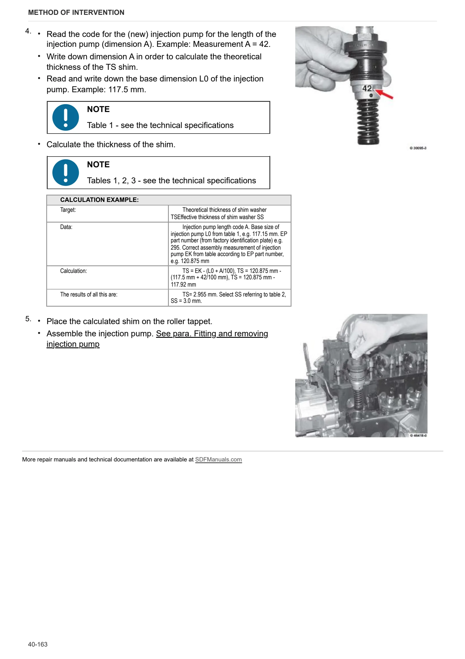
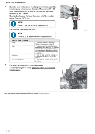
- Fitting and removing injection pump
- Determine the thickness of the shim (engine without injection advance variator)
- Determine the thickness of the shim (engine with injection advance variator)
- Determination of the overall dimensions of the injection pump (engine without the injection advance variator)
- Determination of the overall dimensions of the injection pump (engine with the injection advance variator)
- Fitting and removing injection valves
- Checking the injection valves
- Removal and refitting of the fuel lift pump
- Removal and refitting of the oil pickup pipe
- Removing and fitting the lubricant oil sump pan (cast iron lubricant oil sump)
- Disassembly and assembly of the lubricant oil sump (lubricant oil sump-plate)
- Removal and refitting of the oil cooler
- Disassembly and assembly of the oil radiator housing
- Removal and refitting of the oil pressure switch
- Removal and refitting of the water pump
- Testing the thermostat (after removal)
- Removal and refitting of the thermostat
- Removal and assembly of the fan support
- Removal and refitting of the fan support
- Removal and refitting of the flywheel
- Replacing the starter motor ring gear on the flywheel
C0 – Engine accessories
- Starter motor
- Removing and fitting the engine governor
- Removal and refitting of the exhaust manifold
- Removal and refitting of the fuel filter head.
- Assembly and disassembly of the temperature sender
- Removal and refitting the engine block
- Removal and refitting of the alternator (with drivebelt)
- Disassembly and assembly of the starter
D0 – Transmission
- Transmission – Adjusting endfloat of planetary reduction unit gears
- Transmission – Adjusting spring preload
- Transmission – Adjusting secondary shaft (part No. 927798)
- Transmission – Adjusting differential bearing preload
- Transmission – Adjusting pinion position
- Adjusting mounts – Assembly
- Gearbox internal cover
F0 – Front axle
- Front axle – Adjusting differential
R0 – Rear lift
- ADJUSTING LIFT
Wiring diagrams
Introduction
- Introduction
- Basic electronics for mechanics (1/2)
- Basic electronics for mechanics (2/2)
- Electrical and electronic components (1/2)
- Electrical and electronic components (2/2)
Components
- A – Starting and charging
- B – Fuses
- C – Grounds
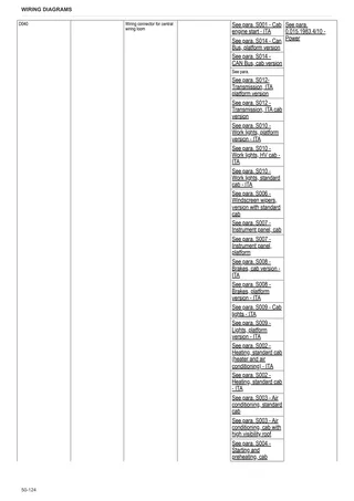
- D – Intermediate connections
- E – On-board instruments and visual and audible indicators
- F – External lights (rotating beacon)
- G – Interior lights
- H – Manual electrical controls (steering column switch)
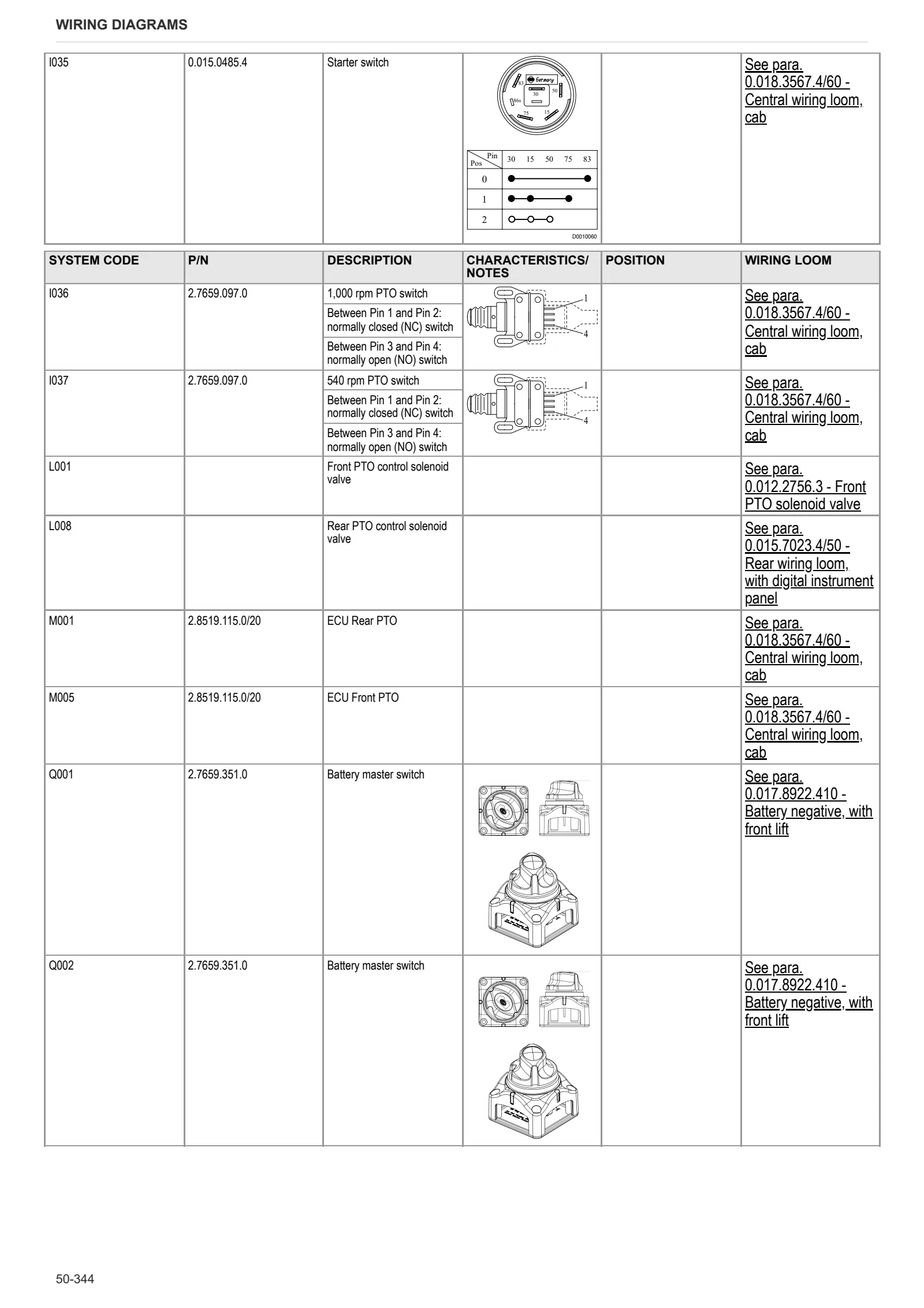
- I – Circuit breakers
- J – Relays
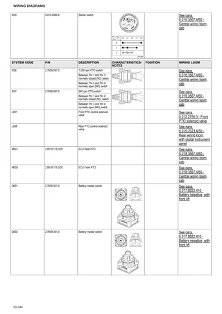
- K – Sensors and transmitters
- K – Sensors and transmitters
- L – Electromagnets and solenoid valves
- M – Electrical/electronic devices, Flasher units and Timers
- N – Electric motors and actuators
- O – Resistors and rheostats
- P – Various services
- Q – Safety devices
- R – Diagnostics
Systems
- S001 – Cab engine start – ITA
- S001 – Cab engine start – USA
- S001 – Cab engine start – ITA
- S001 – Engine start, platform version – USA
- S002 – Heating, standard cab (heater and air conditioning) – ITA
- S002 – Heating, standard cab – ITA
- S002 – Heating, standard cab (heater and air conditioning) – USA
- S002 – Heating, standard cab – USA
- S003 – Air conditioning, standard cab
- S003 – Air conditioning, cab with high visibility roof
- S003 – Air conditioning, cab with high visibility roof – USA
- S003 – Air conditioning, standard cab – USA
- S004 – Starting and preheating, cab
- S004 – Starting and preheating, cab – USA
- S004 – Starting and preheating, platform
- S004 – Starting and preheating, platform – USA
- S005 – PTO, cab version
- S005 – PTO, cab version – USA
- S005 – PTO, platform version
- S005 – PTO, platform version – USA
- S006 – Windscreen wipers, cab with high visibility roof
- S006 – Windscreen wipers, standard cab with heater and air conditioning
- S006 – Windscreen wipers, version with standard cab
- S006 – Windscreen wipers, cab with high visibility roof – USA
- S006 – Windscreen wipers, standard cab with heater and air conditioning – USA
- S006 – Windscreen wipers, version with standard cab – USA
- S007 – Instrument panel, cab
- S007 – Instrument panel, platform
- S007 – Instrument panel, cab version – USA
- S007 – Instrument panel, platform version – USA
- S008 – Brakes, cab version – ITA
- S008 – Brakes, cab version – USA
- S008 – Brakes, platform version – ITA
- S008 – Brakes, platform version \- USA
- S009 – Cab lights – ITA
- S009 – Cab lights – USA
- S009 – Lights, platform version – ITA
- S009 – Lights, platform version – USA
- S010 – Work lights, standard cab – ITA
- S010 – Work lights, standard cab – USA
- S010 – Work lights, HV cab – ITA
- S010 – Work lights, HV cab – USA
- S010 – Work lights, platform version – ITA
- S010 – Work lights, platform version – USA
- S011 – Cab accessories – ITA
- S011 – Cab accessories – USA
- S011 – Platform accessories – ITA
- S011 – Platform accessories – USA
- S012 – Transmission, ITA cab version
- S012- Transmission, ITA platform version
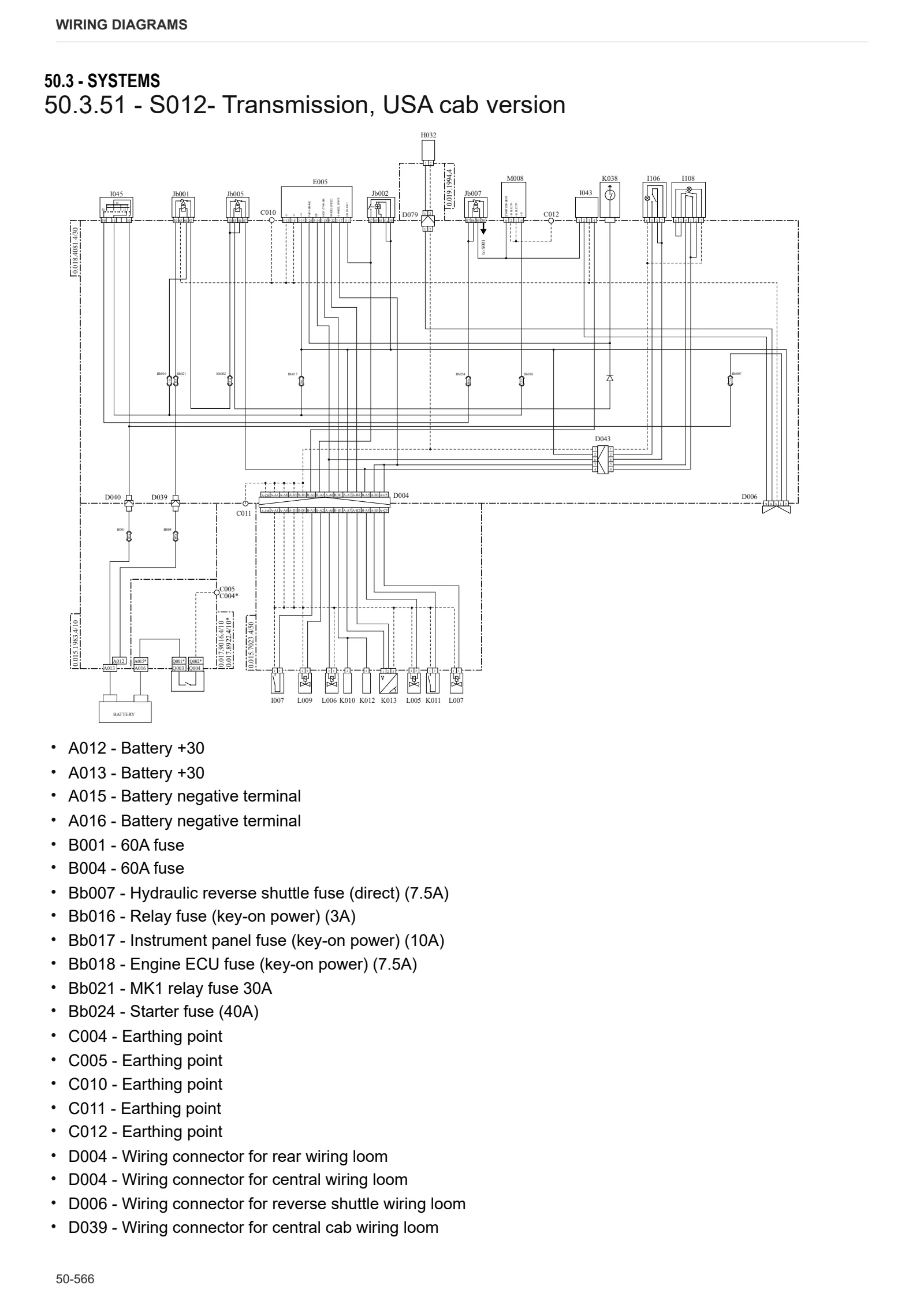
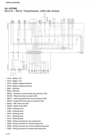
- S012- Transmission, USA cab version
- S012- Transmission, USA platform version
- S014 – CAN Bus, cab version
- S014 – Can Bus, platform version
Wiring harnesses
- 0.010.2147.2 – Heating
- 0.010.2153.2 – Air conditioning
- 0.010.4516.3 – Windscreen wiper, without high visibility cab
- 0.010.6468.3/10 – Pneumatic seat
- 0.011.3597.3 – Windscreen wiper, with high visibility cab
- 0.012.2756.3 – Front PTO solenoid valve
- 0.013.4909.4 – Rear lights
- 0.013.4910.4 – Rear sidelights and turn indicators
- 0.013.6327.4 – Rotating beacon
- 0.014.1645.4/10 – Air-hydraulic braking pressure switch ITA/D
- 0.014.3927.4/40 – Front work light
- 0.014.9195.4/20 – Preheating
- 0.014.9281.4 – Work light and rotating beacon, platform
- 0.015.1418.4/30 – Hydraulic reverse shuttle in cab
- 0.015.1440.4 – Hydraulic reverse shuttle
- 0.015.1983.4/10 – Power
- 0.015.4257.4/10 – PTO sensor – (USA EXPORT)
- 0.015.6123.4 – Rear screen wiper, without high visibility cab
- 0.015.6272.4/40 – Roof, with High Visibility cab
- 0.015.7023.4/50 – Rear wiring loom, with digital instrument panel
- 0.015.7266.4/40 – Air conditioning condenser fan
- 0.015.7309.4 – Front lights and horn
- 0.016.0373.4/30 – Cab power supply
- 0.016.0664.4 – Low rear work lights
- 0.016.0664.4 – Low rear work lights
- 0.016.0849.4 – Front sidelights and turn indicators
- 0.016.0865.4/10 – Roof, with standard cab
- 0.016.0866.4/10 – Work lights and windscreen wiper, without High Visibility cab
- 0.016.2000.4/20 – Engine, version without front lift
- 0.016.2001.4/10 – Engine, version with front lift
- 0.017.0474.4 – Battery positive terminal
- 0.017.1063.4 – Cab earth
- 0.017.8922.410 – Battery negative, with front lift
- 0.017.9016.410 – Battery negative, without front lift
- 0.018.3567.4/60 – Central wiring loom, cab
- 0.018.4081.4/30 – Central wiring loom, cab – USA
- 0.018.5825.4 – Roof, standard cab with heater and air conditioning
- 0.018.5908.4 – Rear lights wiring loom
- 0.018.7845.4/20 – Central wiring loom, platform
- 0.018.8008.4 – Central wiring loom, platform – USA
- 0.019.1994.4 – H/L lever
- 0.019.5535.4 – Front work lights, with HV cab and FOPS roll cage.
- 04215655 – Engine
- 0441.1923.4 – Lower front lights
Service Info
A0 – TRACTOR
- Diagnostics 2026 subscription
- After-sales 2026 subscription
- SERVICE NEWS RESEARCH GUIDE
- Diagnostics 2025 subscription
- After-sales 2025 subscription
- Diagnostics 2023 subscription
- Diagnostics 2024 subscription
- Diagnostics 2022 subscription
- Diagnostics 2021 subscription
- After-sales 2024 subscription
- After-sales 2023 subscription
- After-sales 2022 subscription
- After-sales 2021 subscription
- After-sales 2019 subscription
- SDF Parts and SDF Service DVV 04/2014, version 26
- New function: Download PDF manuals
- Diagnostics – 2020 subscription
- After-sales – 2020 subscription
- After-sales – 2018 subscription
- Service and Spare Parts – 2017 Subscription
- SDF Parts and SDF Service DVDs 05/2014 version 25
- SDF Parts and SDF Service DVDs 03/2013 version 24
B0 – ENGINE
- Flushing the lubrication circuit
- Deutz AG engine oil specifications
- SerDia 2010 updating license file
C0 – ENGINE ACCESSORIES
- Diagnostic protocol – AdBlue – Float level unit
- Filter and prefilter tool p/n 5.9035.865.0
D0 – TRANSMISSION
- Hydraulic shuttle central disc
- Bushes on shuttle input shafts
F0 – FRONT AXLE
- Check the front axle steering knuckles for wear
- Steering behavior check procedure
G0 – BODYWORK – CAB
- Air conditioning system recharging
H0 – HYDRAULIC AND PNEUMATIC SYSTEM|
- Hydraulic CUNA trailer braking kit (ITALY)
- Single connection hydraulic braking kit availability update – only for EUROPEAN market
- Assembly instructions for solenoid valves and cartridge valves
- L0 – ELECTRIC AL SYSTEM