
Document overview
Workshop Manual for DEUTZ FAHR 8310 TTV AGROTRON → WSXMP40200LD10001 from the Series 8 AGROTRON TTV (STAGE 5) family. Digital PDF in English with 353 pages.
The corresponding English table of contents contains 23 sections and 176 individual topics.
Main sections included
- Safety
- Technical characteristics
- Calibrations and electronic diagnosis
- Method of intervention
- Wiring diagrams
- Service Info
Document details
- Brand: DEUTZ FAHR
- Family: Series 8 AGROTRON TTV (STAGE 5)
- Model: 8310 TTV AGROTRON
- Starting serial number: WSXMP40200LD10001
- Document type: Workshop Manual
- Language: English
- Pages: 353
- File size: 106.50 MiB
- Format: Digital PDF download
Compatibility
Before purchasing, verify that your machine model and reference code match DEUTZ FAHR 8310 TTV AGROTRON → WSXMP40200LD10001.
Complete table of contents
Safety
Preface
- Important notes concerning safety
Important safety information
- Recognising hazards
- Indications for persons in contact with the tractor
Safety rules
- Risks during tractor preparation
- Risks during maintenance
- Work on machine systems
- Special disassembly/assembly/inspection procedures
Safety pictograms
- Replacing safety pictograms
Environmental risks
- Hazards associated with the operating environment
Technical characteristics
Engine
- Oil vapour recirculation
- Engine breather filter
- Turbocharging
- EVGT turbocharger
- Turbine speed sensor
- V.G.T. control actuator
- Lubrication
- Oil pump
- Heat exchanger
- Cooling system diagram
- Water pump
- Thermostat
- High pressure pumpCP3
- High pressure regulator
- Fuel temperature sensor
- Boost pressure/air temperature sensor
- Complete fuel pump
- Electro-injector
- Pressure sensor
- Injector
- Differential pressure sensor
- ADBLUE system
- Adblue pump module
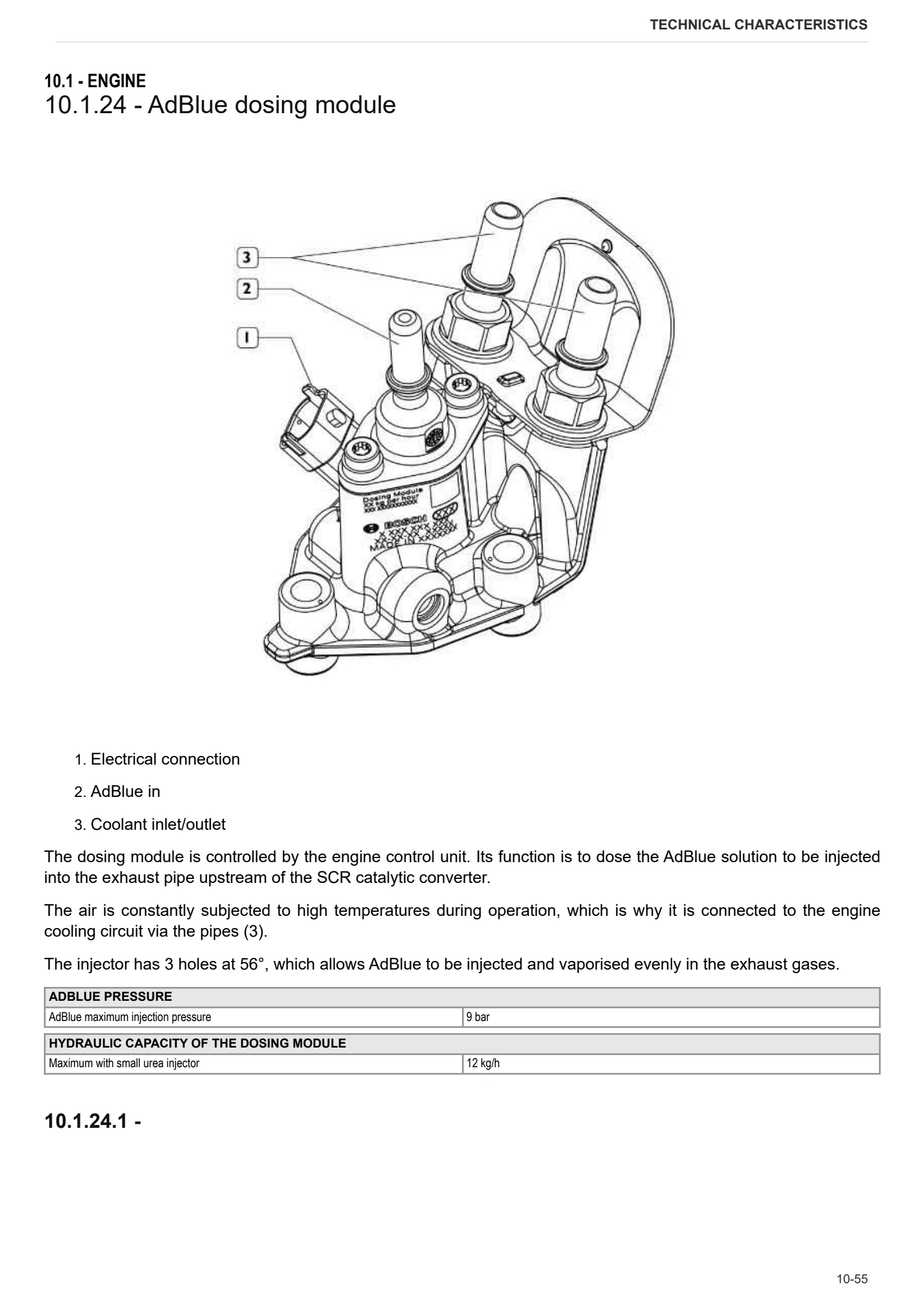
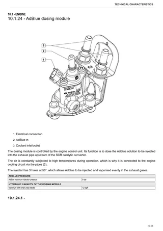
- AdBlue dosing module
- AD_BLUE level indicator
- Diverter valve
- Temperature sensor
- NOx detection sensor
- Temperature and humidity sensor
- Urea Quality Sensor
- Engine oil pressure gauge transmitter
- Engine coolant temperature transmitter
- Tachometer transmitter
- Camshaft speed transmitter
- Engine control unit
- Rail
- Technical data
- Technical data
- Engine tightening torques
- Views of engine
- Locating components
- Description of the fuel system
- Fuel filter
Calibrations and electronic diagnosis
Diagnostic tools
- D-TECH App
- D-Tech and diagnostic ports
ECU alarms
- SDF Severity of alarms
- ECU ALARMS
Method of intervention
- Special tools
B0 – Engine
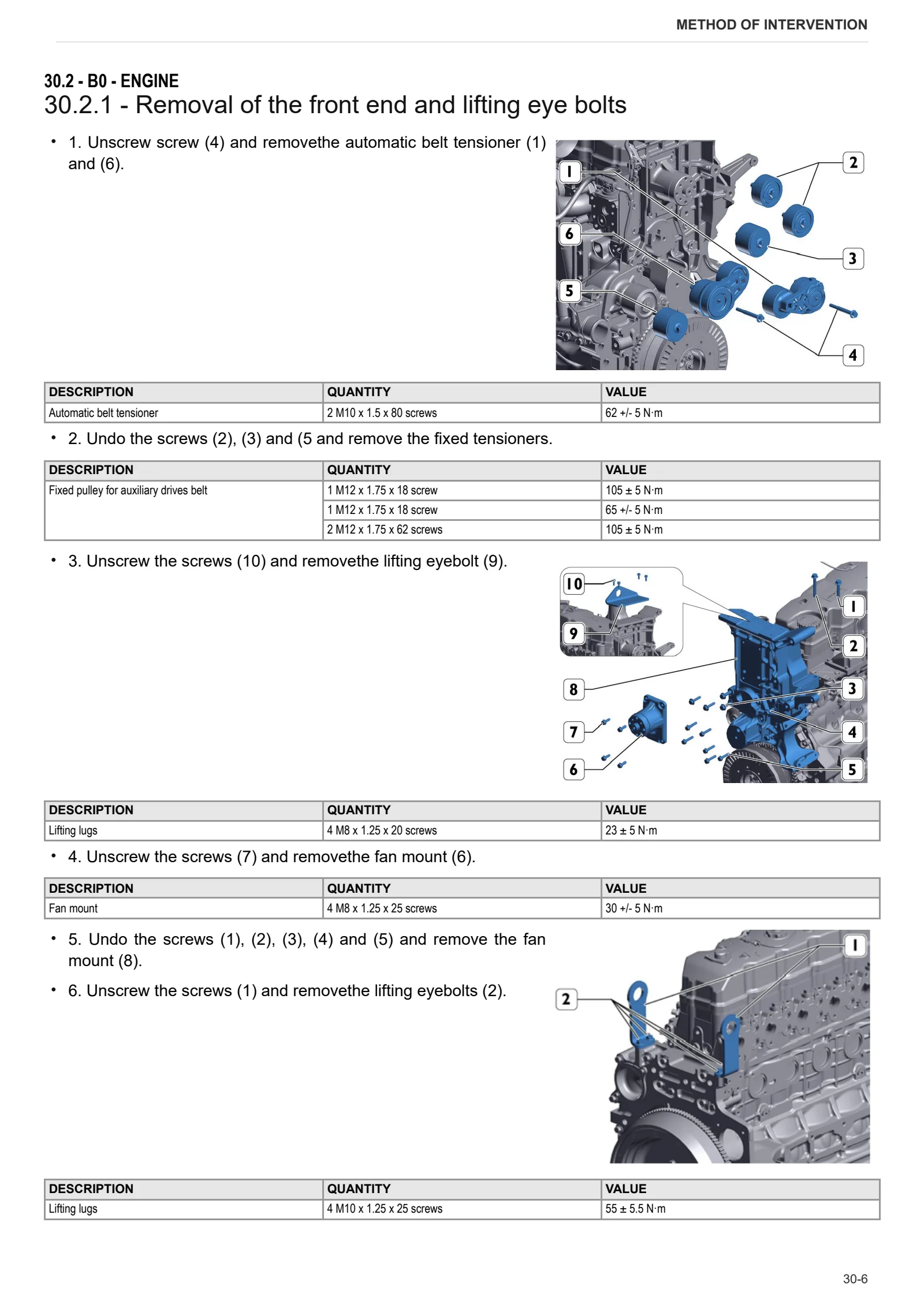
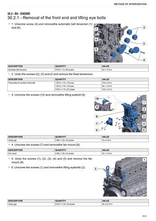
- Removal of the front end and lifting eye bolts
- Assembly of front end and lifting eye-bolts
- Checking cylinder sleeves
- Check the main bearing seats
- Disassembly of the drive shaft fastener ring
- Crankshaft disassembly
- Crankshaft assembly
- Main bearing removal
- Main bearing assembly
- Fitting rear crankshaft seal ring
- Fitting the front crankshaft seal ring
- Crankshaft check
- Check the output shaft axial clearance
- Damper pulley removal
- Damper pulley installation
- Piston removal
- Connecting rod bearing installation
- Piston disassembly
- Assembly of the connecting rod – piston assembly
- Assembly of piston connecting rod assemblies in cylinder sleeves
- Disassembly of the piston rings
- Fitting of piston rings
- Measuring crankpin clearance
- Connecting rod check
- Piston measurement
- Checking piston protrusion
- Piston rings check
- Gear case disassembly
- Gear case assembly
- Timing gear disassembly
- Timing gear assembly
- Camshaft disassembly
- Camshaft check
- Bushings check
- Replacing bushes
- Pushrod tubes check
- Disassembly of the rocker assembly
- Assembly of the rocker assembly
- Disassembly of the cylinder head cover
- Cylinder head cover assembly
- Disassembly of the cylinder head
- Cylinder Head Assembly
- Valve disassembly
- Valve cleaning
- Valve seat replacement
- Valve assembly
- Valve measurement
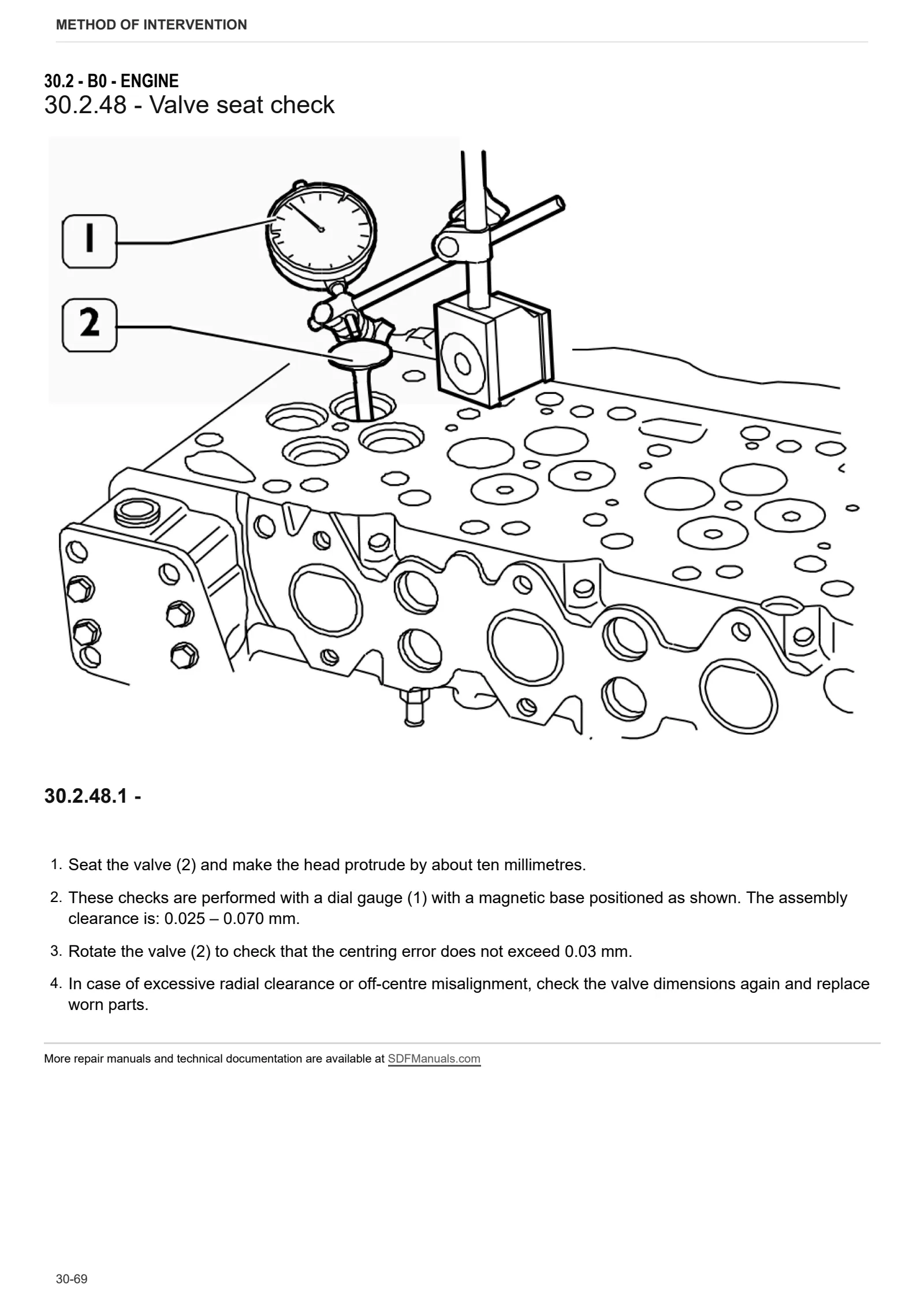
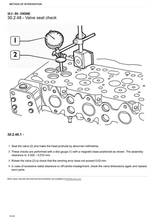
- Valve seat check
- Valve guide check
- Valve spring check
- Rocker clearance check
- Wet cylinder head gasket check
- Cylinder head mating surface check
- Crankcase breather replacement
- Oil sump removal
- Oil sump assembly
- Removal of the lubricant oil and coolant pipes
- Fitting the lubricant oil and coolant pipes
- Oil pump removal
- Oil pump assembly
- Oil pump drive gear replacement
- Changing the engine oil
- Oil filter replacement
- Rail removal
- Rail installation
- Electro-injector removal
- Electro-injectors installation
- High-pressure pump disassembly
- High pressure pump assembly
- Disconnection of the high pressure accumulator
- Reconnection of the high pressure accumulator
- Rail pressure cut-off valve test
- Fuel recirculation test
- Checking the mechanical feed pump
- Oil radiator removal
- Refitting the oil cooler
- Disassembling of the water pump
- Water pump assembly
- Disassembling the thermostat
- Fitting the thermostat
- Water pump drive belt replacement
- Intake manifold removal
- Intake manifold assembly
- Disassembly of the exhaust manifold
- Exhaust manifold assembly
- Disassembly of turbocharger and throttle valve
- Assembly of turbocharger and throttle valve
- Turbocharger check
- Removal of the engine cable
- Engine cable installation
- Assembly of the electro-injector wiring harness support
- Removing the thermostarter
- Refitting the thermostarter
- Flywheel removal
- Flywheel assembly
- Fuel filter support removal
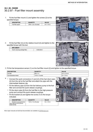
- Fuel filter mount assembly
- AdBlue filter replacement
- Assembly of the engine on the rotary stand
- Disassembly of the engine from the rotary stand
F0 – Front axle
- Front mount
- Front arm
- Front axle
- Drive shaft
G0 – Bodywork – Cab – Platform
- Engine hood and front hood panels
- Front mudguard
M0 – Front PTO
- Front PTO
- Front PTO shaft
N0 – Front lift
- Front lift
- Front lift arm carrier
- Front lift cylinders
- Front top link
S0 – Wheels
- Front wheel
Wiring diagrams
- wiring harness
Service Info
A0 – TRACTOR
- Diagnostics 2026 subscription
- After-sales 2026 subscription
H0 – HYDRAULIC AND PNEUMATIC SYSTEM|
- Hydraulic CUNA trailer braking kit (ITALY)
- Single connection hydraulic braking kit availability update – only for EUROPEAN market
V1 – AFTERMARKET KITS
- Check correct installation of braking KIT