Document overview
Workshop Manual for DEUTZ FAHR 8280W from the Series 8W family. Digital PDF in English with 742 pages.
The corresponding English table of contents contains 42 sections and 210 individual topics.
Main sections included
- Introduction
- Safety
- Technical characteristics
- Calibrations and electronic diagnosis
- Method of intervention
- Wiring diagrams
- Service Info
Document details
- Brand: DEUTZ FAHR
- Family: Series 8W
- Model: 8280W
- Document type: Workshop Manual
- Language: English
- Pages: 742
- File size: 285.43 MiB
- Format: Digital PDF download
Compatibility
Before purchasing, verify that your machine model and reference code match DEUTZ FAHR 8280W.
Complete table of contents
Introduction
- Tightening Torques
- Pump tightening torques
- Wheel rim to hub screws and nuts tightening torques
- Tightening torques for nuts and bolts of electrical connections
- Installation of solenoid valves and cartridge valves
- Installation of quick couplers
- Units of measurement and conversion factors
- Maintenance intervals
- Thread lock adhesives, sealants and lubricants
Safety
Preface
- Important notes concerning safety
Important safety information
- Recognising hazards
- Indications for persons in contact with the tractor
Safety rules
- Risks during tractor preparation
- Risks during maintenance
- Work on machine systems
- Special disassembly/assembly/inspection procedures
Safety pictograms
- Replacing safety pictograms
Environmental risks
- Hazards associated with the operating environment
Technical characteristics
Engine
- Tightening Torque for the Engine Main Bolts
- Tightening torques of clamp
- Main specifications
- Tensioner and belt assembly
- Water pump
- Water outlet pipe assembly
- Crankshaft pulley assembly
- Flywheel assembly
- Piston cooling nozzle assembly
- Engine block assembly
- Fitting Clearance of Engine Main Parts
- Technical Data 8280 W
- Reversable Fan
Engine accessories
- Turbocharger assembly
- Low-pressure fuel pipe assembly
- High-pressure fuel pipe assembly
- Common rail pipe assembly
- Fuel injection pump assembly
- Starter assembly
- Hoisting ring
- Valve train assembly
- Fuel Tank
- Additional Fuel Tank
Transmission
- Rear PTO
Front axle
- Definition of views
- Serial number plate
- Conversion tables
- Tightening torque specifications
- Maintenance points
- Mandatory procedure for draining oil
Bodywork – Cab – Platform
- Main technical data
- Attaching/detaching implements to/from the front lift
- Dimensions and weights of the tractor
- Front wheel drive and differential lock
- Transmission controls and indicator lamps
- External views of the tractor
- Rear lift
- Selecting work range, gear and drive direction
- Viste interni cabina
- Front lift
Hydraulic system
- Idraulic circuit Full Optional
- Idraulic circuit basic
Electrical equipment
- Electronic control unit (ECU)
Calibrations and electronic diagnosis
Diagnostic tools
- D-Tech and diagnostic ports
Diagnostic tool screens
- Commissioning procedure (EOL)
- ECU reset (CAB)
- Set vehicle model
- Transmission Control Unit (TCU) initialization
- Maximum vehicle speed
- Tyre type
- ASM (Automatic Steering Management)
- Air brake
- Front power take-off (PTO)
- ISO 11786
- Clutch Pedal calibration
- Draft sensor calibration
- Rear hitch position calibration
- Steering angle calibration
- Main clutch calibration
ECU alarms
- SDF Severity of alarms
- ECU ALARMS
Engine alarms
- List of Diagnostic Fault Codes
Method of intervention
B0 – Engine
- Complete engine Part 1
- Complete engine Part 2
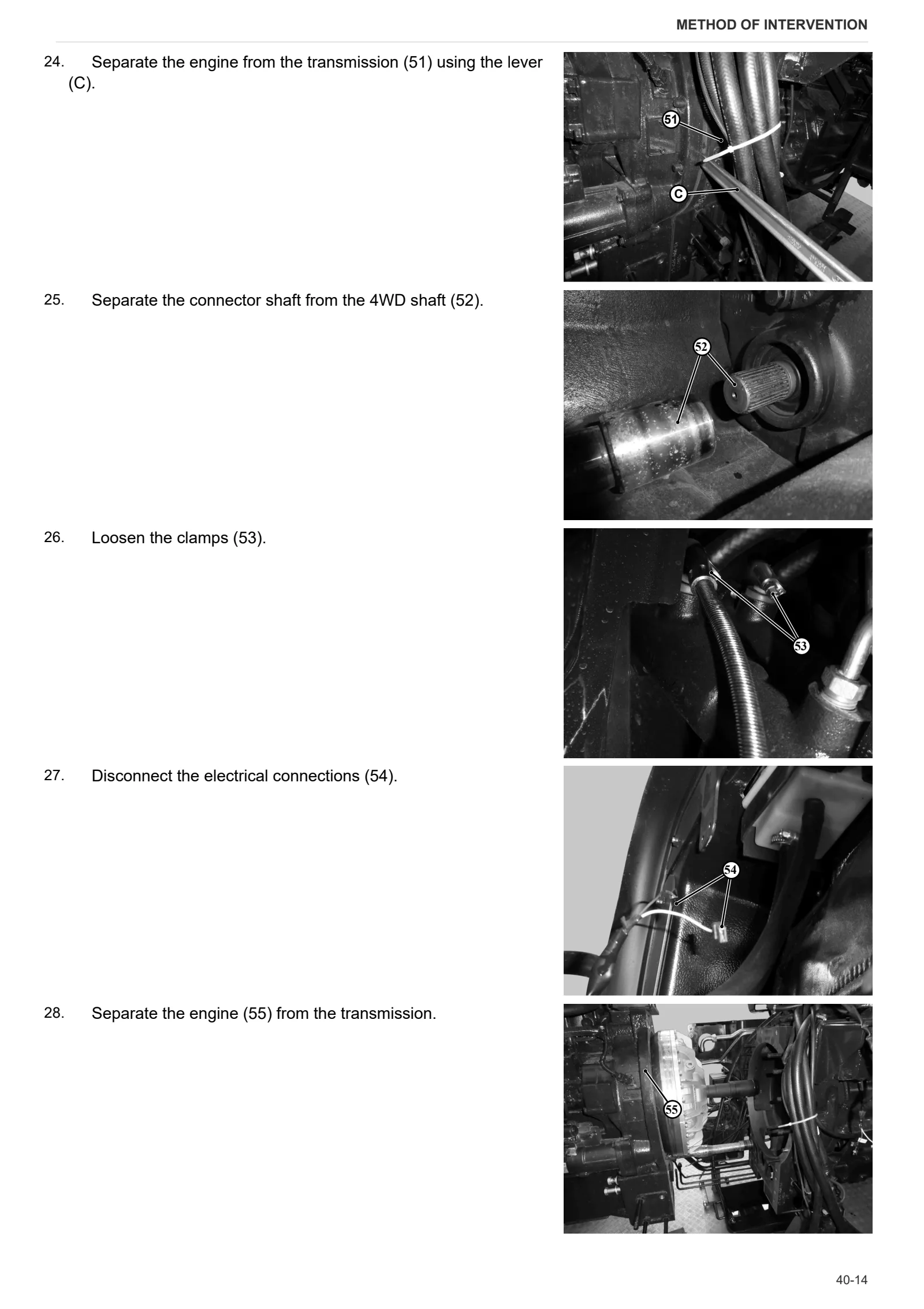
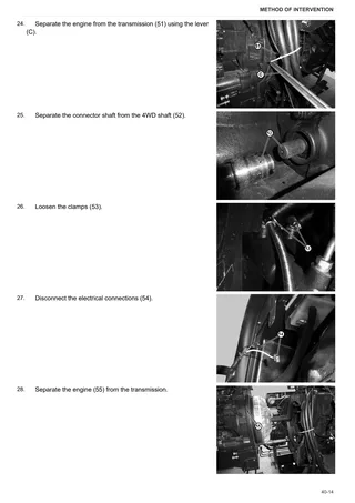
- Separating the engine from the transmission Part 1
- Separating the engine from the transmission Part 2
- Checking radiator cleanliness
- Oil change
- Replacement of fuel filter and filter element
- Check and adjustment of valve clearance
- Intake manifold assembly
- Oil-gas separator assembly
- Replacement valve train
- Cylinder head
- Gear train
- Oil suction strainer
- Oil pump
- Piston and connecting rod
- Crankshaft
- Engine block assembly
C0 – Engine accessories
- Fuel system
- Air compressor assembly
- Fuel injector
- Air filter
- Cyclone filter
- Fuel tank
- Exhaust silencer
- Drain pipe
- Fuel filter mount
- Radiator assembly Part 1
- Radiator assembly Part 2
- Auxiliary fuel tank
D0 – Transmission
- Checking the transmission oil level
- Changing the transmission oil
- Changing the transmission and rear axle oil filter
- Clutch housing
- Flexible coupling and flywheel
- 4WD output shaft
- Disassembly and reassembly of the Single Speed P.T.O.
- Disassembly and reassembly of the dual speed P.T.O.
- Disassembly and reassembly of Solenoid Valves
- Disassembly and reassembly of the remote control
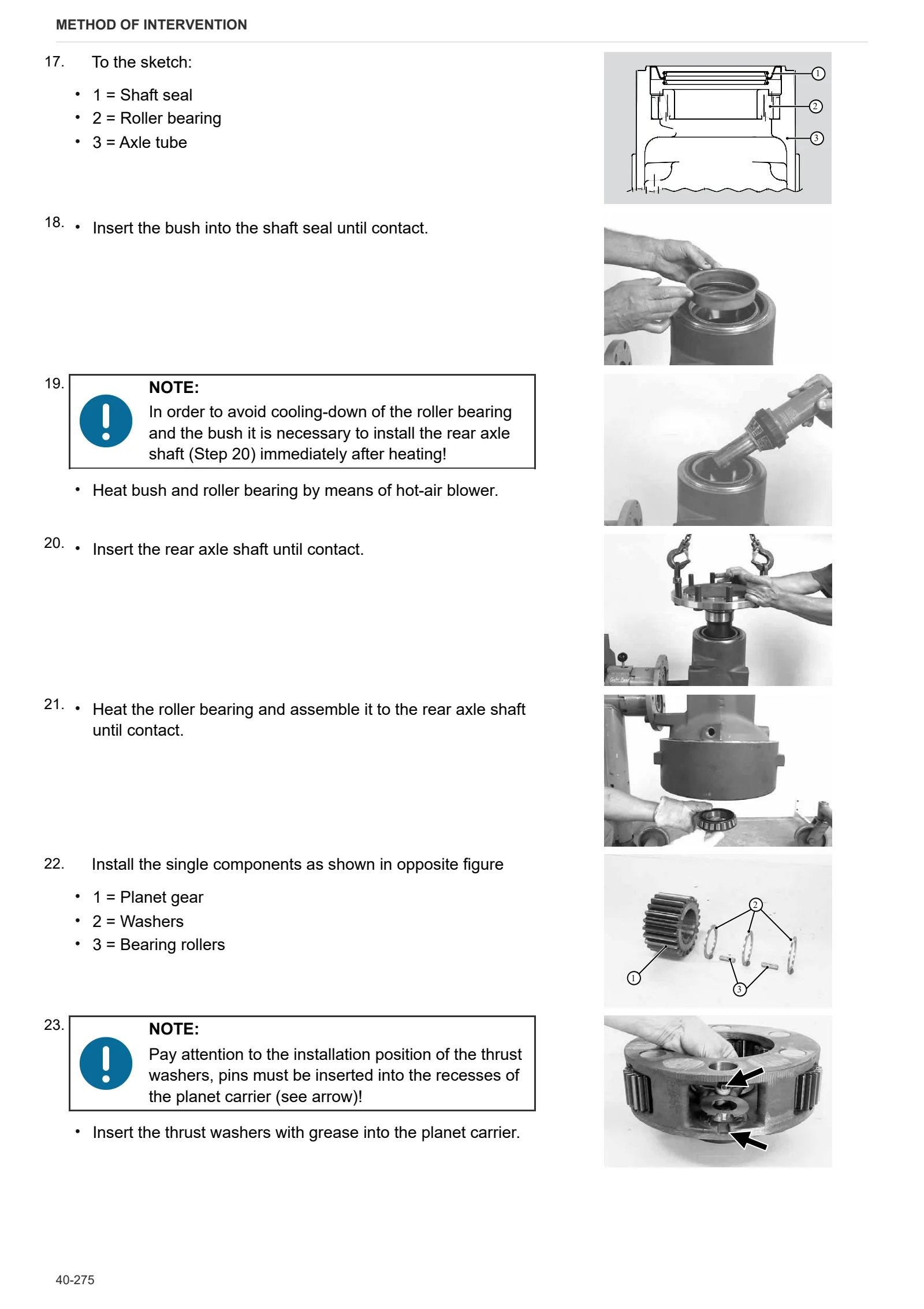
- Rear axle gear box detachment and attachment
- Pump control unit
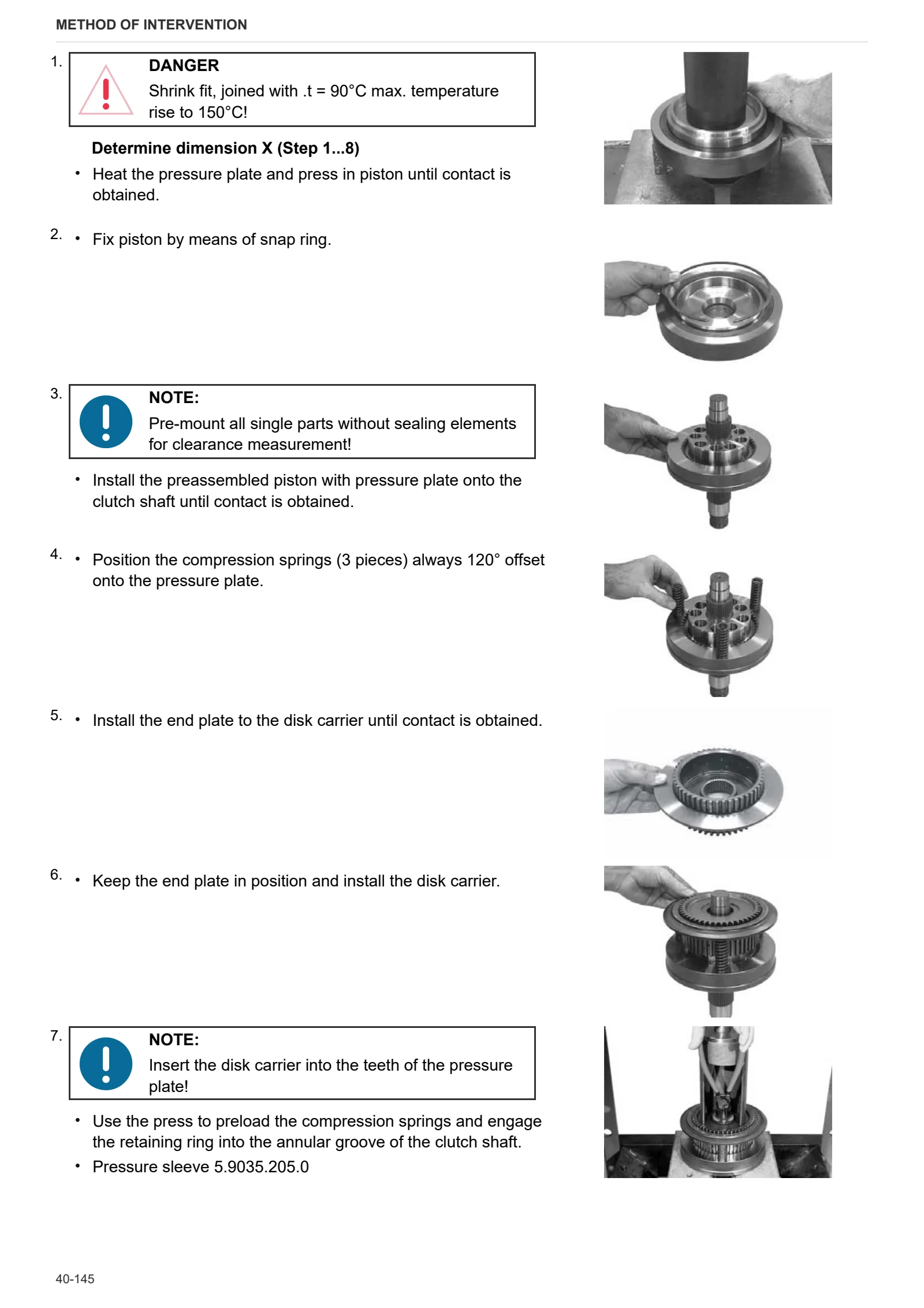
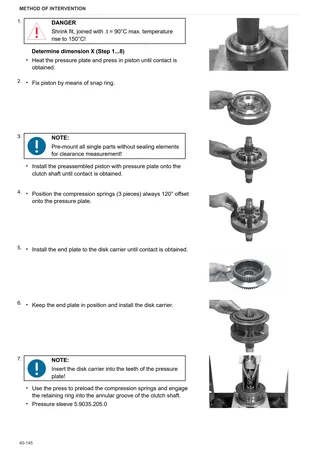
- Powershift clutches
- Powershift clutch – A/C clutch disassembly
- Powershift clutch – B/D clutch disassembly
- Powershift clutch – F/G clutch disassembly
- Front wheel drive shaft
- Creeper gear control
- Main clutch
- Mechanical gear engagement control
- Main shaft
- Secondary shaft
- Gearbox pre-assembly
- Gearbox cover
- Clutch axial clearance adjustment
- Adjustment of creeper gear control engagement limit.
- Separate and Mounting transmission from the Rear Axle
- Disassembly and reassembly of the Output
- Disassembly and reassembly of the Brake Actuation
- Disassembly and reassembly of the RH Brake
- Disassembly and reassembly of the LH Brake
- Disassembly and reassembly of the Differential
- Disassembly and reassembly of Oil Supply
- Electro-hydraulic shift control module
- Control pump gear
- Gearbox pump fixture
- Transmission oil heat exchanger
- Disassembly and reassembly of the Power Lift
F0 – Front axle
- Pivot brackets
- Planetary reduction gearbox
- Stub axle and steering sensor
- Steering cylinder
- Differential assembly
- Bevel pinion
- Engine speed sensor
- Special tools
- 4WD shaft
- Front axle
- Carrier with front axle
G0 – Bodywork – Cab – Platform
- Complete air conditioner unit
- Roof panel
- Empty and charge the air conditioning system
- Cowl
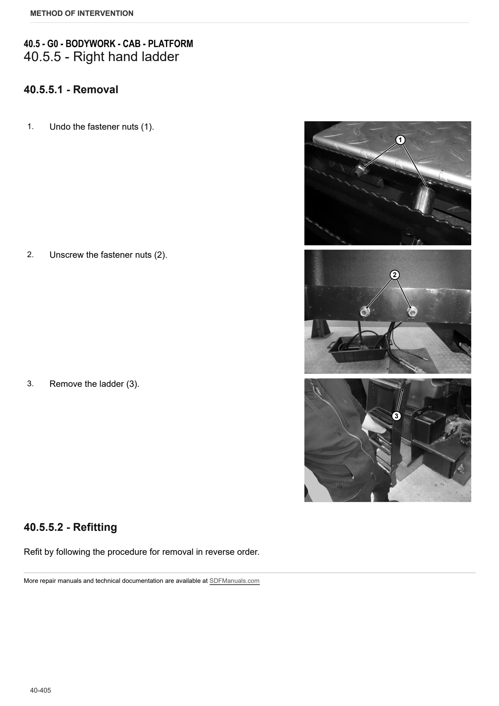
- Right hand ladder
- Front mudguard
- Floor
- Right hand console
- Oil pressure gauge
- Seat
- Air conditioning condenser
- Steering wheel
- iMonitor
- Cab
- Battery mount
- Hood subframe Part 1
- Hood subframe Part 2
- Left hand console
- Steering column selector stalk and dashboard
- Rear pillar
- Passenger seat
- Brake master cylinders
H0 – Hydraulic system
- Auxiliary utility oil tank
- Orbitrol hydrostatic steering unit
- Rear ancillary distributor
L0 – Electrical system
- Battery
M0 – Front PTO
- Front PTO
N0 – Front lift
- Front lift
- Front lift arms
R0 – Rear lift
- Rear lift cylinder
S0 – Wheels
- Rear wheel
- Front Wheels
V0 – Ballast – towing hitches
- Front ballast
Wiring diagrams
Wiring harnesses
- Wiring looms
Service Info
A0 – TRACTOR
- Diagnostics 2026 subscription
- After-sales 2026 subscription
- SERVICE NEWS RESEARCH GUIDE
- Diagnostics 2025 subscription
- After-sales 2025 subscription
- Diagnostics 2024 subscription
- After-sales 2024 subscription
C0 – ENGINE ACCESSORIES
- Diagnostic protocol – AdBlue – Float level unit
- Filter and prefilter tool p/n 5.9035.865.0
- SCR AREA DAMAGED SENSORS
F0 – FRONT AXLE
- Bevel gear set loosing screws
H0 – HYDRAULIC AND PNEUMATIC SYSTEM|
- Hydraulic CUNA trailer braking kit (ITALY)
- Single connection hydraulic braking kit availability update – only for EUROPEAN market
L0 – ELECTRIC AL SYSTEM
- SerDia4.0
- PTO switch not working
V1 – AFTERMARKET KITS
- Check correct installation of braking KIT
- Instructions for kit aftersales