

Document overview
Digital Workshop Manual documentation for model DEUTZ FAHR 6130 → WSXKA80200LD10001 from the Series 6 Agrotron (STAGE 3A – STAGE 4) family. Language: English; 2,114 pages.
The corresponding English table of contents contains 49 sections and 721 individual topics.
Main sections included
- Introduction
- Safety
- Technical characteristics
- Calibrations and electronic diagnosis
- Method of intervention
- Wiring diagrams
- Service Info
Document details
- Brand: DEUTZ FAHR
- Family: Series 6 Agrotron (STAGE 3A – STAGE 4)
- Model: 6130
- Starting serial number: WSXKA80200LD10001
- Document type: Workshop Manual
- Language: English
- Pages: 2,114
- File size: 545.21 MiB
- Format: Digital PDF download
Compatibility
Before purchasing, verify that your machine model and reference code match DEUTZ FAHR 6130 → WSXKA80200LD10001.
Complete table of contents
Introduction
- Tightening torques
- Wheel nut/screw tightening torques
- Tightening torques for nuts and bolts of electrical connections
- Installation of solenoid valves and cartridge valves
- Installation of quick couplers
- Units of measurement and conversion factors
- Fixing the steering wheel
- Spool valves
- Introduction – Engines
Safety
Preface
- Important notes concerning safety
Important safety information
- Recognising hazards
- Indications for persons in contact with the tractor
Safety rules
- Risks during tractor preparation
- Risks during maintenance
- Work on machine systems
- Special disassembly/assembly/inspection procedures
Safety pictograms
- Replacing safety pictograms
Environmental risks
- Hazards associated with the operating environment
Technical characteristics
- Starter motor
Engine accessories
- AdBlue® technical characteristics
- Fuel tank
- AdBlue tank
- Pressure/temperature sender
- Pressure transducer – 1
- Pressure transducer – 2
- Pressure transducer – 3
- Pressure sensor
- Temperature sender- 1
- Temperature sender- 2
- Temperature sender- 3
- Temperature sender- 4
- Temperature sender- 5
- Speed indicator
- NOx sensor (12 V)
Transmission
- Transmission
- Transmission
- Hydraulic reverse shuttle
- Rear power take off
Rear axle
- Rear axle
- Rear axle
- Rear differential, mechanical version
- Rear differential with ASM
Front axle
- Front axle 2 WD
- Front axle 4 WD
- Front axle 4 WD
- Disc type front differential lock (ASM)
- Planetary reduction gearbox with 4 WD axle
- Planetary reduction gearbox
- Front brakes
Bodywork – Cab – Platform
- General introduction to the A/C system
- Air conditioning system
- A/C system – Version with standard roof
- Air conditioning system controls – High-visibility roof system
- Air conditioning system – Diagnostics
- Air conditioning compressor
Hydraulic system
- Hydraulic circuit, base version (“Mother Regulation” version)
- Hydraulic circuit, full house version (“Mother Regulation” version)
- Hydraulic circuit, base version with LS pump (“Mother Regulation” version)
- Hydraulic circuit, full house version (“Mother Regulation” version)
- Hydraulic circuit, optional version (“Mother Regulation” version)
- Hydraulic transmission circuit, base version (“Mother Regulation” version)
- Hydraulic transmission circuit, full house version (“Mother Regulation” version)
- Location of hydraulic accumulators
- Hydraulic pump unit
- 45 cc variable displacement pump
- Gear pump
- Transfer pump
- Suction pump filter
- Delivery line filter
- Braking system
- Park Brake system
- Park Brake valve
- Hydraulic Engine Brake
- Power steering 80 -160cc
- Power steering SDD 125-250cc
- Power steering SDD 115-240cc
- Distributors unit – Mechanical version
- Distributors unit – Electrical version
- Front axle suspension
- 3-way priority valve, suspended axle – Mechanical distributor version
- Bistable valve for LS signal, suspended axle – Electronic distributor version
- Engaging dual traction with ASM
- Electrohydraulic gear control unit
Electrical equipment
- FARMotion engine sensors and components
Front PTO
- Front PTO
Front lift
- Front lift
Rear lift
- Rear lift control valve
Calibrations and electronic diagnosis
- ECUs
Diagnostic tools
- D-Tech and diagnostic ports
- D-TECH App
- SerDia2010
Commissioning and calibrating the tractor
- Commissioning procedure (EOL)
- ECU Reset
- Vehicle model selection
- Distributors configuration
- Maximum vehicle speed
- Tyre type
- Language
- Measurement unit
- Range
- Steering Double Displacement (SDD)
- ASM
- Front Axle Suspension (FAS)
- PTO Syncro
- Front Power Take-Off (PTO)
- Radar
- Automatic Air Conditioning
- Hydraulic Engine Brake (HEB)
- eVisco fan
- Agrosky
- Four-Wheel Drive (4WD)
- Pneumatic trailer brake
- Hydraulic trailer brake
- Isobus
- iMonitor
- ISO 11786
- Front loader (stoll)
- Valve programming
- electronic Trailer Control Valve (eTCV) parameters configuration
- Hand brake position calibration
- Clutch pedal calibration
- Throttle pedal calibr
- Hand gas calibration
- Rear hitch position calibration
- Steering angle calibration
- Front suspension calibration
- PowerShuttle calibration
- Slope sensor calibration
ECU alarms
- SDF Severity of alarms
- ECU ALARMS
Software management
- Engine dataset upgrade
- Download Dataset FARMotion & Flash ECU
Method of intervention
B0 – Engine
- Replace the crankshaft O-ring (flywheel end)
- Fitting and removing seal seat
- Checking the cylinder
- Assembly and disassembly of the crankshaft bearing
- Check the crankshaft bearings
- Check the endfloat of the crankshaft
- Fitting and removing the piston cooling nozzle
- Removing and refitting the camshaft bearing (camshaft removed from engine)
- Checking the camshaft bearing (camshaft removed from engine)
- Fitting and removing transition pipe
- Removing and fitting the oil pressure regulator valve
- Blanking elements
- Blanking elements
- Lubricant oil measuring device
- Oil filler neck (crankcase, intake side)
- Pipe (crankcase breather)
- Valve needle (crankcase breather)
- Removing and fitting lubricant oil sump (heavy version)
- Removing and fitting the V belt pulley/poly-V belt pulley
- Removing and fitting the counterweight drive shaft
- Topping up with oil
- Assembly and disassembly of the crankshaft bearing
- Check the crankshaft
- Removing and fitting the flywheel (fixing elements)
- Disassembling and assembling the sensor wheel
- Disassembly and reassembly of connecting rod shank
- Check the connecting rod shank
- Disassembling and assembling the piston
- Check the piston
- Disassembling and assembling the piston rings
- Check the piston rings
- Compression test (with injectors removed from engine)
- Cleaning the V-belt
- Fitting and removing the high pressure pump
- Disassembling and assembling the cylinder head cover
- Measuring piston protrusion
- Assembly and disassembly of the valves
- Turbocharger shield plate
- Replacing the crankshaft seal ring (flywheel side).
- Disassembling and assembling the gear casing (fastener elements)
- Blanking cover (PTO-B)
- Fitting and removing the regulator valve
- Intermediate gear
- Assembly and disassembly of the camshaft
- Check the camshaft
- Disassembly and assembly of the control elements
- Removing and fitting the lubricant oil radiator
- Fitting the lubricant oil filter (vrankcase)
- Disassembling and assembling the oil suction pipe
- Removing and fitting the lubricant oil pipe
- Removing and refitting the lubricant oil return pipe – lower section – (turbocharger)
- Removing and refitting the lubricant oil return pipe – upper section – (turbocharger)
- Lubricant oil pipe
- Fitting and removing the high pressure pump
- High pressure pump, mating with gear (with gear case disassembled)
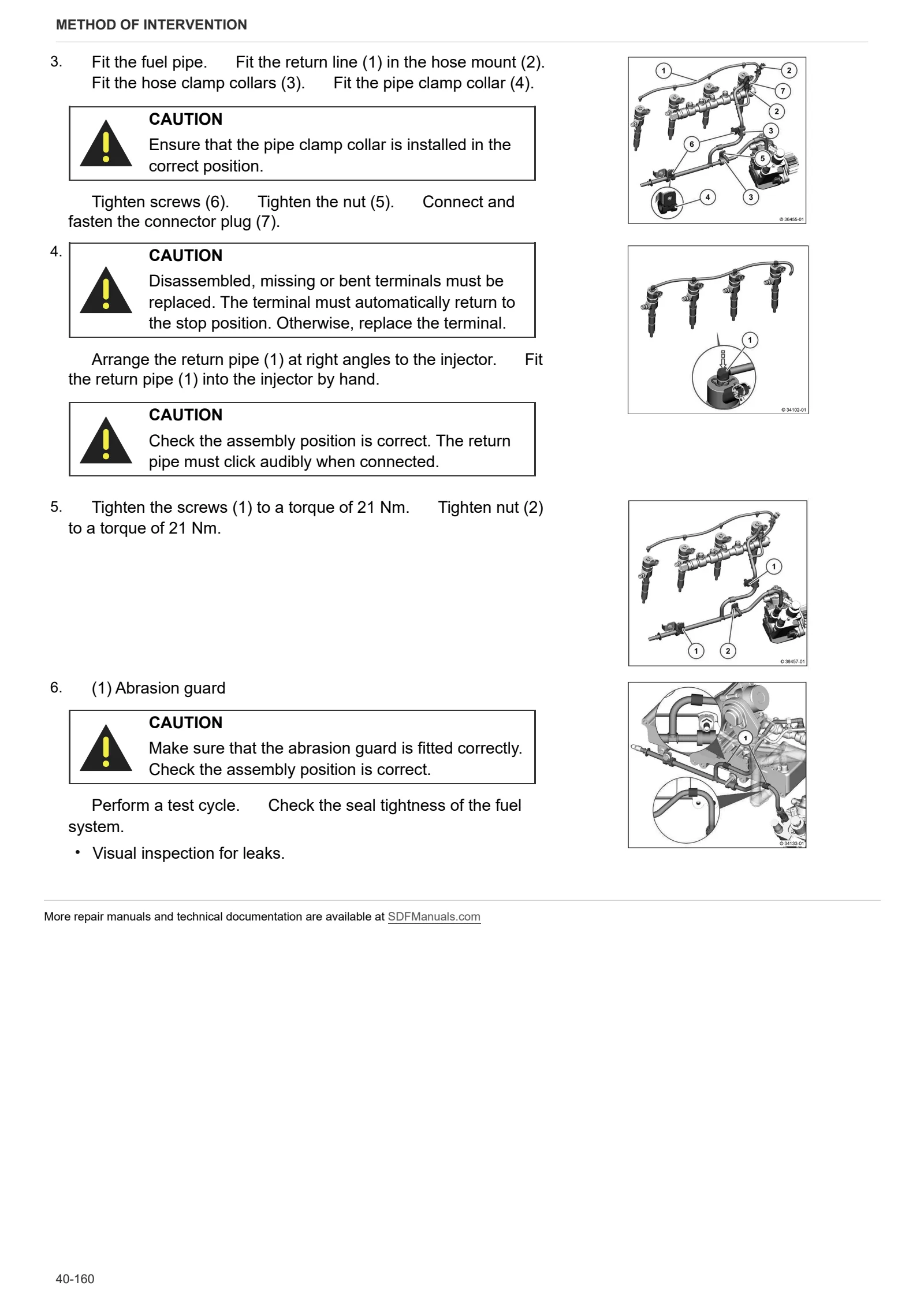
- Removing and fitting the injector
- Fuel filter
- Fuel filter
- Fitting the fuel pressure transducer
- Fuel delivery pump (electric)
- Fuel delivery pump (electric)
- Removing and fitting the rail
- Disassembling and assembling the pressure cut-off valve (rail)
- Disassembly and assembly of the rail pressure sensor
- Removing and fitting fuel line (injector, rail, high pressure pump)
- Removing and fitting fuel line (injector, rail, high pressure pump)
- Removing and fitting fuel line (injector, rail, high pressure pump)
- Fuel pipe (quick connector)
- Disassembling and assembling charge air pipe
- Intake manifold (turbocharger)
- Charge air manifold
- Removal and refitting of the supply air pressure/temperature sender
- Removing and fitting the coolant pump
- Pulley (V belt, poly-V belt)
- Removing and fitting the thermostat (with engine on workbench)
- Checking the thermostat (on bench)
- Line
- Line
- Removing and fitting the exhaust manifold
- Disassembling and assembling the thermostat housing (fastener elements)
- Flexible hose (thermostat housing – crankcase)
- Disassembling and assembling the butterfly valve
- Disassembling and assembling the radiator
- Removing and fitting the exhaust gas recirculation valve
- Removing and fitting the exhaust manifold
- Disassembling and assembling the Venturi pipe
- Connection (crankcase, exhaust gas recovery, coolant pipe)
- Blanking screw (thermostat housing, exhaust gas recirculation, coolant pipe)
- Support
- Support
- Support
- Removing and fitting the compensation pipe (exhaust gas recirculation system)
- Removing and fitting the temperature sender (exhaust gas recirculation system)
- Removing and fitting the pressure transducer (exhaust gas recirculation system)
- Shield plate (exhaust pipe)
- Coolant pipe (radiator – thermostat housing, exhaust gas recovery system)
- Venturi pipe
- Pipe (crankcase, exhaust gas recirculation, coolant pipe)
- Pipe (thermostat housing, exhaust gas recovery, coolant pipe)
- Disassembling and assembling the turbocharger
- Removing and fitting belt tensioner (ribbed V belt)
- Fitting and removing the console (ribbed V-belt, level 1)
- Engine mounting
- Engine mounting
- Engine mounting
- Engine mounting
- Fitting and removing rotation/lock tool
- Disassembly and assembly of the connector box
- Connector casing
- Removing and fitting the glowplugs
- Removing and fitting the compensator (turbocharger)
- Support
- Support
- Removing and fitting the exhaust manifold
- Removing and refitting refrigerant compressor
- Fastening elements
- Removing and fitting hydraulic pump drive
- Disassembling the cylinder heads
- Complete engine
- Separating engine / transmission
- A/C compressor belt
- Power take off gear backlash adjustment
C0 – Engine accessories
- Fastening elements
- Aspirator fan
- Blower fan
- Adapter
- Removing and fitting the temperature sender
- Removing and fitting the pressure transducer
- Disassembly and assembly of the starter
- Fastening elements
- Removing and fitting the alternator (fastener elements)
- Disassembly and assembly of the starter
- Alternator
- Mount fasteners (starter motor relay)
- Temperature sender (coolant)
- Fitting the pressure transducer (fuel pressure / lubricant oil pressure)
- Relay (heater, thermo-starter, glow plugs)
- Relay, mount (glow plugs)
- Relay, mount (thermo-starter)
- Wiring harness (fasteners)
- Wiring harness (mounting plate fasteners)
- Connector cable (relay – thermo-starter)
- Check the seal of the cooling system
- Removing and fitting the supply air pressure/temperature sender
- Fastening elements
- Fastening elements
- Fastening elements
- Fastening elements
- Crankshaft speed sensor
- Camshaft speed sensor
- Fitting the pressure transducer (lubricant oil pressure)
- Removing and fitting the glow plugs
- Disassembling and assembling the NOx sensor
- Removing and installing SCR (Selective Catalytic Reduction) pressure transducer (exhaust gas back pressure)
- Fitting and removing the SCR (Selective Catalytic Reduction) metering unit
- Flushing the SCR delivery pump (Selective Catalytic Reduction)
- Flushing/Checking SCR (Selective Catalytic Reduction) metering unit
- Flushing the SCR (Selective Catalytic Reduction) pipe (delivery pump – metering unit)
- Blanking components (diesel particulate filter, SCR catalytic converter, NOx sensor, temperature sender and DPF differential pressure sender)
- Screw plug, SCR catalytic converter (NOx sensor)
- Hole blanking screw, (catalytic converter – temperature sender)
- Support
- Connector coupling
- Connector coupling
- Temperature sender (inlet air and ambient air temperature)
- VBand clamp (3″ exhaust pipe)
- VBand clamp (turbocharger)
- SCR delivery pump (Selective Catalytic Reduction)
- Inlet module
- Fitting and removing the temperature sender (ahead of diesel oxidation catalytic converter)
- SCR (Selective Catalytic Reduction) exhaust gas back pressure transducer (mixing section)
- Temperature sender (inlet air and ambient air temperature)
- SCR (Selective Catalytic Reduction) coolant pipe
- DOC (diesel oxidation catalyst) catalytic converter / DPF (diesel particulate filter)
- SCR (Selective Catalytic Reduction) catalytic converter
- SCR delivery pump (Selective Catalytic Reduction)
- Console
- SCR tank (Selective Catalytic Reduction)
- Replacing the coolant
- Bleeding the fuel circuit
- Engine air intake fan
- Coolant radiator
- Compensation tank
- Complete radiator pack
- Diesel radiator
- Intercooler
- Intercooler, oil and fuel radiators
- Air filter
- Rigid air filter pipe
- Fuel tank
- DOC catalytic converter
- Catalytic converter exhaust silencer disassembly
- Air compressor for utilities
- Exhaust silencer
- AdBlue pump filter
D0 – Transmission
- Changing the transmission oil
- Separating the gearbox housing from the rear gearbox housing
- Torsionally flexible coupling and engine flywheel
- Shuttle unit – Complete assembly
- Disassembly of the shuttle unit
- Disassembly of the cover unit
- Clutch assembly: Forward Drive
- Disassembly of the forward drive clutch assembly
- Clutch assembly: Reverse
- Disassembly of the reverse drive clutch assembly
- Gearbox input shaft
- Gearbox input shaft – Version with HML
- Primary shaft disassembly – Version with HML
- Secondary shaft disassembly – Version with HML
- Shimming Secondary Shaft Bearing – Assembly standard: 939177
- Gearbox assembly with HML
- Complete gearbox assembly – Version with HML
- Disassembling the HML unit
- Disassembling the outer HML housing
- Shimming HML Shaft – Assembly standard: 939177
- Disassembling the HML planetary gear carrier
- Disassembling the Low range clutch – Version with HML
- Refitting and adjusting HML unit
- HML unit assembly procedure – Assembly standard: 939177
- Assembling and adjusting gearbox
- Adjusting the range shaft
- Assembling the range selector assembly
- Range gearbox and Creeper gears
- Internal range reduction gear controls
- Disassembly of the internal range reduction gear controls
- Disassembling the gear selector lever
- Disassembling the supercreeper gear shaft
- Adjusting differential – bevel gear set
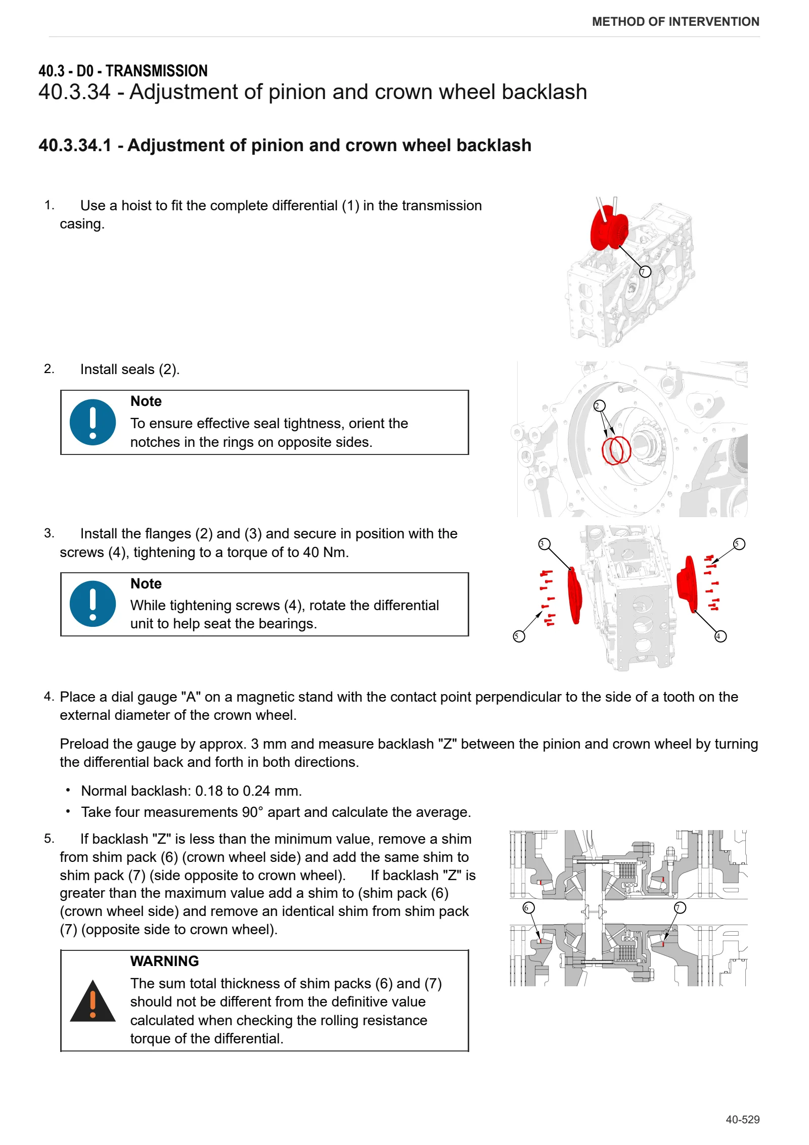
- Adjustment of pinion and crown wheel backlash
- Removing the rear pinion
- Dual traction output shaft
- 4WD engagement device
- Disassembly of the 4WD engagement device
- Disassembly of dual traction output shaft
- Rear PTO control clutch
- Disassembly of the PTO clutch
- Pump drive PTO – external gear
- Pump drive PTO – internal gear
- PTO output shaft
- Disassembling the PTO output shaft – 4 speed version
- Disassembling the rear PTO output flange shaft
- Disassembling the ground speed PTO output flange shaft
E0 – Rear axle
- Bleeding the braking system
- Right-hand rear axle
- Left-hand rear axle
- Removing right/left hand rear axle
- Park Brake assembly
- Park Brake unit disassembly
- Rear differential
- Removing rear differential
F0 – Front axle
- Dual traction shaft (DT)
- Steering bar/tie-rod
- Carrier with front axle (4WD)
- Adjusting front carrier – engine alignment
- Front axle 4WD
- Front axle adjusting endfloat
- Steering cylinders
- Removing steering cylinders
- Suspended axle pivot bracket
- Differential assembly
- Disassembly of the differential locking device
- Disassembling the differential assembly – pinion
- Adjusting differential preload and pinion-crown wheel backlash
- Pinion positioning and preload adjustment
- Planetary reduction gearbox
- Disassembling the planetary reduction gearbox
- Steering knuckle housing and half-shaft
- Adjustment of steering knuckle housing and axle shaft
- Front axle brake discs
- Steering angle adjustment
- Steering angle adjustment
- Suspended axle pivot bracket
G0 – Bodywork – Cab – Platform
- Cab
- Cab access steps
- Front mudguards
- Empty and charge the air conditioning system
- A/C unit
- A.C. Electronic Control Unit replacement
- Air conditioning compressor
- Air conditioning condenser
- Disassembling the air conditioning condenser
- Dehydrator filter
- Engine hood and front hood panels
- Engine hood mount
- Lower hood guard
- Battery mount
- Windscreen wiper motor
- Steering wheel
- Steering column
- Instrument cluster
- Instrument cluster
- Brake pedals
- Brake master cylinders
- Sun blind
- Headliner trim panel
- Roof panel
- Headliner trim
- Anti-pollen filter
- External rear-view mirrors
- Driver seat
- Passenger seat
- Main gear lever
- Rear distributor control levers
- Range shift lever
- PTO selector lever
- Electronic throttle control
- Disassembling the electronic throttle control
- Cab mat
- Control console and right hand side cab trim
- Left hand side cab trim
- Adjustment of Bowden cable
- Door handle
- Roof hatch
H0 – Hydraulic system
- Load Sensing (LS) ancillary pump
- Lubrication pump
- Disassembling the lubrication pump
- Disassembling the hydraulic pump drive unit
- Hydraulic steering pump (16 cc)
- Left hydraulic pump (32 cc)
- Right hydraulic pump (14 cc)
- Supplementary pump
- Power steering
- Transmission oil radiator
- Rear auxiliary utility distributor
- Disassembling the rear ancillary utility distributor
- Suspended axle accumulator block
- HML valve unit
- Shuttle solenoid valves assembly
- Services solenoid valve assembly
- Brake logic block
- Front braking valve
- Trailer air braking valve and air tank
- Air tanks
- Testing operation of pneumatic trailer braking system (eTCV)
- Pneumatic trailer braking system (eTCV)
- Trailer braking electronic control unit (WABCO)
L0 – Electrical system
- Battery
- Alternator
- Electronic engine control unit
- Brake pedal union sensor
M0 – Front PTO
- Front PTO
- Disassembling front PTO
- Disassembling the front PTO clutch-brake assembly
- Clutch pack end float values check
R0 – Rear lift
- Complete rear lift
- Disassembling the lift assembly (SAC)
- Lift cylinder
- Stabiliser tie-rod carrier
- Bushes
- Auxiliary lift cylinders
- 3-point linkage
S0 – Wheels
- Front Wheels
- Rear wheels
V0 – Ballast – towing hitches
- Tow hook sled
- Tow hook
V1 – AFTERMARKET KITS
- Pneumatic braking kit – cod. 9.CZ189.91.0
Wiring diagrams
Components
- HLHP Control unit (VCU)
- HLHP Control unit (VCU)
- HLHP Control unit (OCU)
- HLHP Control unit (G-TECU)
- ECU ISO 11786 Control unit
- Engine Control Unit
- Engine Control Unit
- Trailer air braking control unit (ETCV)
- SCR Control unit
- LED worklights control unit
- A – Starting and charging
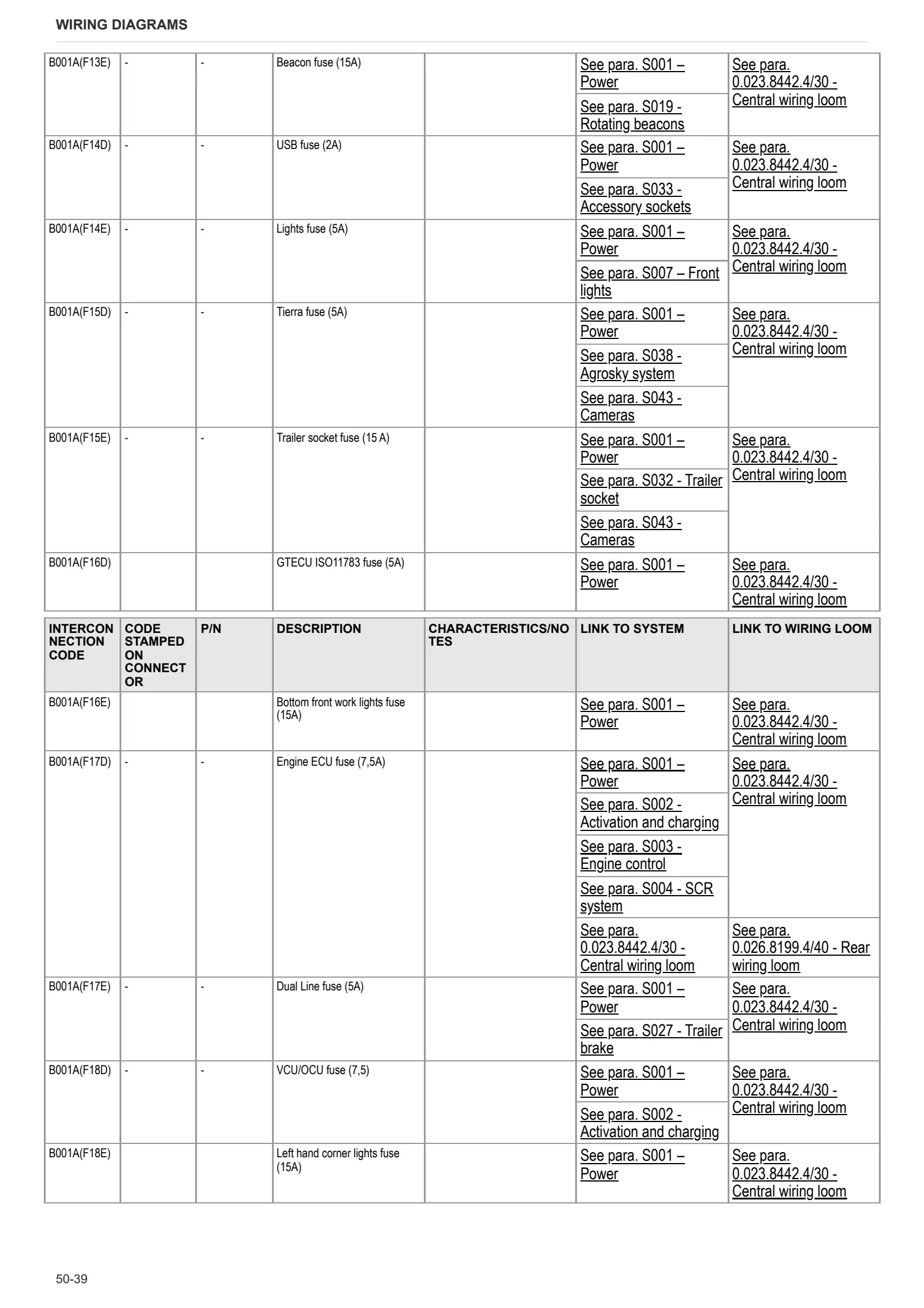
- B – Fuses
- C – Grounds
- D – Intermediate connections
- E – On-board instruments and visual and audible indicators
- F – External lights (rotating beacon)
- G – Interior lights
- H – Manual electrical controls (steering column stalk)
- I – Circuit breakers
- J – Relays
- K – Sensors and transmitters
- L – Electromagnets and solenoid valves
- M – Electrical/electronic devices, Flasher units and Timers
- N – Electric motors and actuators
- O – Resistors and rheostats
- P – Various services
- R – Diagnostics
- A – Starting and charging
- B – Fuses
- C – Grounds
- D – Intermediate connections
- E – On-board instruments and visual and audible indicators
- F – External lights (rotating beacon)
- G – Interior lights
- H – Manual electrical controls (steering column stalk)
- I – Circuit breakers
- J – Relays
- K – Sensors and transmitters
- L – Electromagnets and solenoid valves
- M – Electrical/electronic devices, Flasher units and Timers
- N – Electric motors and actuators
- O – Resistors and rheostats
- P – Various services
- R – Diagnostics
Systems
- S001 – Power
- S002 – Activation and charging
- S003 – Engine control
- S004 – SCR system
- S005 – Engine cooling
- S006 – Wipers / horn
- S007 – Front lights
- S008 – Rear lights
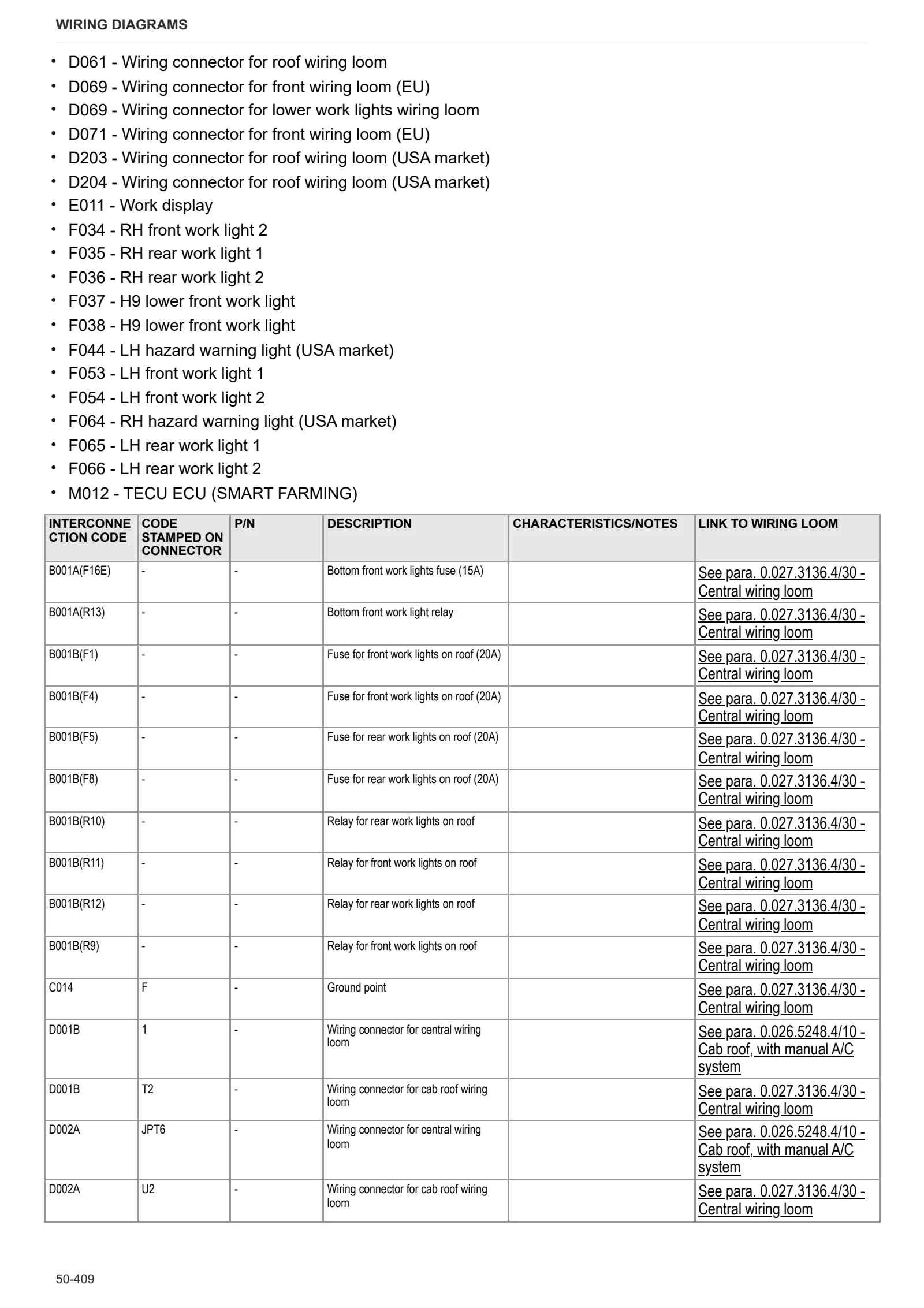
- S009 – Work lights
- S010 – Power take off (PTO)
- S011 – Vehicle CAN network
- S012 – Engine CAN network
- S013 – Auxiliary CAN network
- S014 – Distributor CAN network
- S015 – “ISOBUS” CAN network
- S016 – Brake system and brake lights
- S017 – SDD / ASM
- S019 – Rotating beacons
- S020 – Turn signal / hazard warning lights
- S021 – Internal illumination
- S022 – Radio
- S023 – Manual air conditioner
- S024 – Automatic air conditioning
- S025 – Mirror adjustment / mirror and rear screen defrost
- S026 – Diagnostic connectors
- S027 – Trailer brake
- S028 – Transmission / gearbox
- S029 – Differential / 4WD
- S030 – Front axle suspension
- S031 – Distributors
- S032 – Trailer socket
- S033 – Accessory sockets
- S034 – Provision for ISO11786
- S035 – Front loader
- S036 – Front implement
- S037 – Rear implement
- S038 – Agrosky system
- S039 – Smart Farming system
- S040 – Cornering lights
- S041 – Digital instrument / instrument cluster
- S042 – Hydraulic reverse shuttle
- S043 – Cameras
- S001 – Power
- S002 – Activation and charging
- S003 – Engine control
- S004 – SCR system
- S005 – Engine cooling
- S006 – Wipers / horn
- S007 – Front lights
- S008 – Rear lights
- S009 – Work lights
- S010 – Power take off (PTO)
- S011 – Vehicle CAN network
- S012 – Engine CAN network
- S013 – Auxiliary CAN network
- S014 – Distributor CAN network
- S015 – “ISOBUS” CAN network
- S016 – Brake system and brake lights
- S017 – SDD / ASM
- S019 – Rotating beacons
- S020 – Turn signal / hazard warning lights
- S021 – Internal illumination
- S022 – Radio
- S023 – Manual air conditioner
- S024 – Automatic air conditioning
- S025 – Mirror adjustment / mirror and rear screen defrost
- S026 – Diagnostic connectors
- S027 – Trailer brake
- S028 – Transmission / gearbox
- S029 – Differential / 4WD
- S030 – Front axle suspension
- S031 – Distributors
- S032 – Trailer socket
- S033 – Accessory sockets
- S034 – Provision for ISO11786
- S035 – Front loader
- S036 – Front implement
- S037 – Rear implement
- S038 – Agrosky system
- S039 – Smart Farming system
- S040 – Cornering lights
- S041 – Digital instrument / instrument cluster
- S042 – Hydraulic reverse shuttle
- S043 – Cameras
Wiring harnesses
- Wire colour reference table
- 0.011.3824.4/10 – Rotating beacon
- 0.012.2756.3 – Front PTO
- 0.014.1567.4/30 – Front wiper motor – opening windscreen version
- 0.014.1645.4/10 – Hydraulic trailer braking pressure switch wiring
- 0.014.8453.4 – Front wiper motor – fixed windscreen version
- 0.015.5429.4/40 – Sockets for front controls
- 0.016.8489.4 – Engine brake
- 0.017.0496.4/10 – H9 lower rear work lights
- 0.017.8425.4/10 – Trailer socket, EU
- 0.017.9761.4/20 – Distributors 6/7
- 0.019.4379.4/20 – Roof panel
- Rear mudguards
- 0.019.5702.4/10 – ISO 11786
- 0.019.5777.4 – Front axle suspension solenoid valve
- 0.019.8827.4 – SDD (rapid steer system)
- 0.020.9559.4 – Front/rear camera
- 0.021.1196.4/10 – Low work lights
- 0.021.1217.4 – Heater
- 0.021.1915.4/10 – Relays and switches for front loader
- 0.021.8276.4 – Camera
- 0.023.1280.4/20 – Engine
- 0.023.1282.4/10 – Injectors, 4-cylinder version
- 0.023.7690.4 – Power cables
- 0.023.7779.4/20 – Engine
- 0.023.7818.4/10 – ISO 11783 – Rear line
- 0.023.8442.4/30 – Central wiring loom
- 0.023.9500.4/10 – Cooling fan and pressure sensor
- 0.024.2826.4/10 – Alternator – preheat
- 0.024.8482.4/10 – Mechanically engaged front loader 1
- 0.025.1281.4/10 – Gearbox
- 0.026.0179.4/10 – Distributors 1/5
- 0.026.1183.4 – NOx sensor 2
- 0.026.1301.4 – Mechanically engaged front loader 2
- 0.026.1946.4 – Front sensors
- 0.026.3491.4 – Jump Start
- 0.026.3531.4/10 – Hydraulic trailer brake
- 0.026.4756.4 – Electrically adjustable and heated rear-view mirrors (RH side)
- 0.026.4756.4 – Electrically adjustable and heated rear-view mirrors (LH side)
- 0.026.4924.4 – Front (EU)
- 0.026.5226.4/20 – Smart Farming
- 0.026.5248.4/10 – Cab roof, with manual A/C system
- 0.026.5309.4/10 – Cab roof, with automatic A/C system
- 0.026.5325.4/10 – Front work lights on cab roof (LED version)
- 0.026.5325.4/10 – Rear work lights on cab roof (LED version)
- 0.026.5452.4/10 – Rear screen wiper and heated rear screen
- 0.026.5594.4 – OCU control unit
- 0.026.5702.4/10 – Fuel prefilter pump
- 0.026.5866.4 – Front work lights on cab roof (H9 halogen version)
- 0.026.5913.4/10 – X25 dual camera kit
- Cowl
- 0.026.6130.4 – Front loader
- 0.026.6197.4/10 – iMonitor X25
- 0.026.6377.4 – SBA ASM WAS adapter
- 0.026.6498.4 – Console with electric controls
- 0.026.6605.4 – Agrosky AES
- 0.026.8199.4/40 – Rear wiring loom
- 0.027.1782.4 – Camera 1
- 0.027.1783.4 – Camera 2
- 0.027.2444.4 – Pneumatic trailer brake
- 0.027.2494.4 – Agrosky SR10 antenna (Visual Guidance)
- 0.027.2732.4 – Agrosky SRC40 antenna (Assisted Steering)
- 0.027.2929.4/20 – DCU metering module
- 0.027.2959.4/10 – Power cables
- 0.027.3136.4/30 – Central wiring loom
- 0.027.6393.4/10 – Hydraulic braking
- 0.027.7230.4 – Console with mechanical controls
- 0.028.1208.4 – Ground wiring loom (AIR PREX)
- 0.031.6150.4 – Start enable
- 0.033.8944.4 – LED TOP light adapter
- 04422324.4/10 – ISO 11786 socket
Service Info
A0 – TRACTOR
- Diagnostics 2026 subscription
- After-sales 2026 subscription
- SERVICE NEWS RESEARCH GUIDE
- Diagnostics 2025 subscription
- After-sales 2025 subscription
- Diagnostics 2023 subscription
- Diagnostics 2024 subscription
- Diagnostics 2022 subscription
- Diagnostics 2021 subscription
- After-sales 2024 subscription
- After-sales 2023 subscription
- After-sales 2022 subscription
- After-sales 2021 subscription
C0 – ENGINE ACCESSORIES
- SERVICE NEWS – DEF Unit – Wrong level indication
- Diagnostic protocol – AdBlue – Float level unit
- Filter and prefilter tool p/n 5.9035.865.0
- SCR AREA DAMAGED SENSORS
F0 – FRONT AXLE
- Bevel gear set loosing screws
- Steering behavior check procedure
G0 – BODYWORK – CAB
- Air conditioning system recharging
H0 – HYDRAULIC AND PNEUMATIC SYSTEM|
- Hydraulic CUNA trailer braking kit (ITALY)
- Single connection hydraulic braking kit availability update – only for EUROPEAN market
L0 – ELECTRIC AL SYSTEM
- SerDia4.0
- iMonitor x35 malfunctioning
- GO-ANYWHERE DIAGNOSTICS
- Bad visualizazion of wiring diagram on technical documentaion
- M108 – Wiring harness modification
- iMonitor SW upgrade & iMonitor UBOOT update instruction
- iMonitor software HORIZON 5.02
- Lost connection diagnostic tools
- iMonitor SW upgrade
- PTO switch not working
V1 – AFTERMARKET KITS
- Check correct installation of braking KIT
- Instructions for kit aftersales