Document overview
Workshop Manual for DEUTZ FAHR 6040 HTS from the 6040 Eco family. Digital PDF in English with 877 pages.
The corresponding English table of contents contains 15 sections and 225 individual topics.
Main sections included
- Introduction
- General information
- Engine
- Engine accessories
- Hydraulic system
- Electrical equipment
- Service Info
Document details
- Brand: DEUTZ FAHR
- Family: 6040 Eco
- Model: 6040 HTS
- Document type: Workshop Manual
- Language: English
- Pages: 877
- File size: 44.56 MiB
- Format: Digital PDF download
Compatibility
Before purchasing, verify that your machine model and reference code match DEUTZ FAHR 6040 HTS.
Complete table of contents
Introduction
- Introduction
- Safety warnings
- General safety instructions
- Safety instructions – maintenance and repair
- Tightening Torques
General information
- Components of the TCD 2012 L04/L06 4V DCR engine
- Technical data of Engine TCD 2012 4V
- Tightening requirements TCD 2012 L04/L06 4V DCR (Lv.2) engine
- Tightening requirements TCD 2012 L04/L06 4V DCR (Lv.3) engine
- Wheel rim to hub screws and nuts tightening torques
- Tightening torques for nuts and bolts of electrical connections
- Conversion tables
- Tightening values, screwing classes
- Lubricants
- Seal materials
- One-component adhesive
- Approved list of lubricating oil quality class – DEUTZ
- Securing bush support tightening values
- Maintenance and repair
- Care and maintenance
Engine
- Tools for engine disassembly and reassembly
- Workshop tools for engine disassembly and reassembly
- Removing and installing the crankcase bleeding
- Removing and installing torsional vibration damper
- Alternator, fuel pump, coolant pump and fan drivebelt
- Removing and installing the flywheel
- Removing and installing the belt tensioner (V-rib belt)
- Air conditioning compressor drivebelt
- Air conditioning compressor drivebelt tensioning
- Checking piston overhang
- Removing and installing the rocker arm housing
- Disassembling, assembling and checking the rocker arm and rocker arm bracket
- Checking and setting the valve clearance
- Changing the engine oil
- Checking that the radiator is clean
- Removing and installing the cooler (exhaust gas recirculation)
- Removing and installing the flutter valve (exhaust gas return)
- Checking the coolant thermostat when uninstalled
- Removing and installing the fan drive
- Removing and installing the actuator (exhaust gas return)
- Removing and installing the exhaust line
- Removing and installing the shutoff valve (exhaust gas recirculation)
- Compression test
- Setting the shut-off valve (exhaust return)
- Removing and installing the turbocharger
- Assembly and disassembly of the engine on the assembly stand
- Adjustment of valve clearance
- Fitting and removing rocker seat
- Removing and refitting rocker seat, checking
- Disassembly and assembly of the cylinder head
- Measuring piston protrusion
- Valve assembly and disassembly
- Valve check
- Check the valve guide
- Check the valve residual
- Test data and settings
- Check the endfloat of the crankshaft
- Check the crankshaft
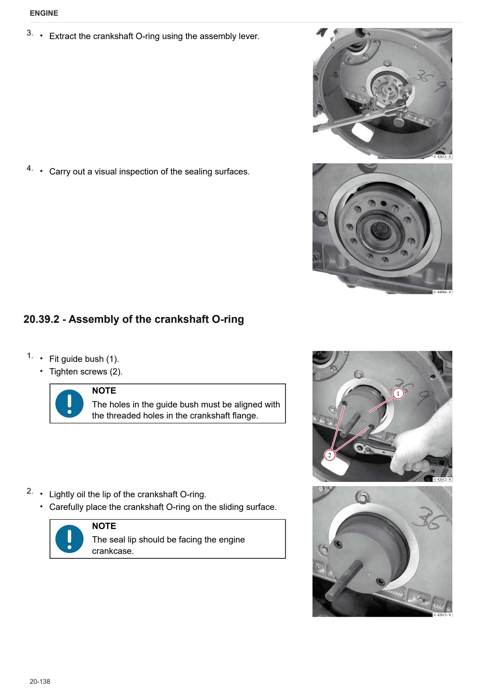
- Replace the crankshaft O-ring (flywheel end)
- Replacing the crankshaft O-ring (opposite end to flywheel)
- Check the connecting rod drum
- Assembly and disassembly of the crankshaft
- Disassembly and assembly of the piston and connecting rod drum
- Check the piston
- Check the piston rings and piston grooves
- Assembly and disassembly of piston cooling nozzles
- Removal and refitting of the crankcase breather
- Check the cylinder
- Removal and refitting of the front cover (opposite end to flywheel)
- Disassembly and assembly of the gear case cover
- Assembly and disassembly of the camshaft
- Check the camshaft
- Removal and refitting of the rotation device
- Removal and refitting of the heater
- Removal and refitting of the turbocharger
- Removing and fitting the butterfly valve (exhaust gas recovery)
- Removing and fitting the cooler (exhaust gas recovery)
- Removing and fitting regulator unit (exhaust gas recovery)
- Removing and fitting the cutoff valve (exhaust gas recovery)
- Adjusting the cutoff valve (exhaust gas recovery)
- Removing and fitting the fuel delivery pump (driven by ribbed V-belt) (L3)
- Removal and refitting of the fuel control unit
- Removal and refitting of the high-pressure pump (installation position A)
- Removal and refitting of the high-pressure pump (installation position B)
- Removal and refitting of the common rail
- Removal and refitting of the injectors
- Removal and refitting of the pressure cut-off valve
- Removal and refitting of the oil sump pan.
- Removal and refitting of the oil pickup pipe
- Removal and refitting of the oil cooler
- Removal and refitting of the lube oil cooler housing
- Removal and refitting of the water pump
- Testing the thermostat (after removal)
- Removal and refitting of the fan drive system
- Removal and refitting of the fan drive system
- Removal and refitting of the torsional vibration damper
- Removing and fitting belt tensioner (ribbed V-belt)
- Removal and refitting of the flywheel
Engine accessories
- Disassembly and assembly of the speed indicator (crankshaft)
- Removal and refitting of the camshaft speed sensor
- Removal and refitting of the exhaust manifold
- Removal and refitting of the fuel filter head.
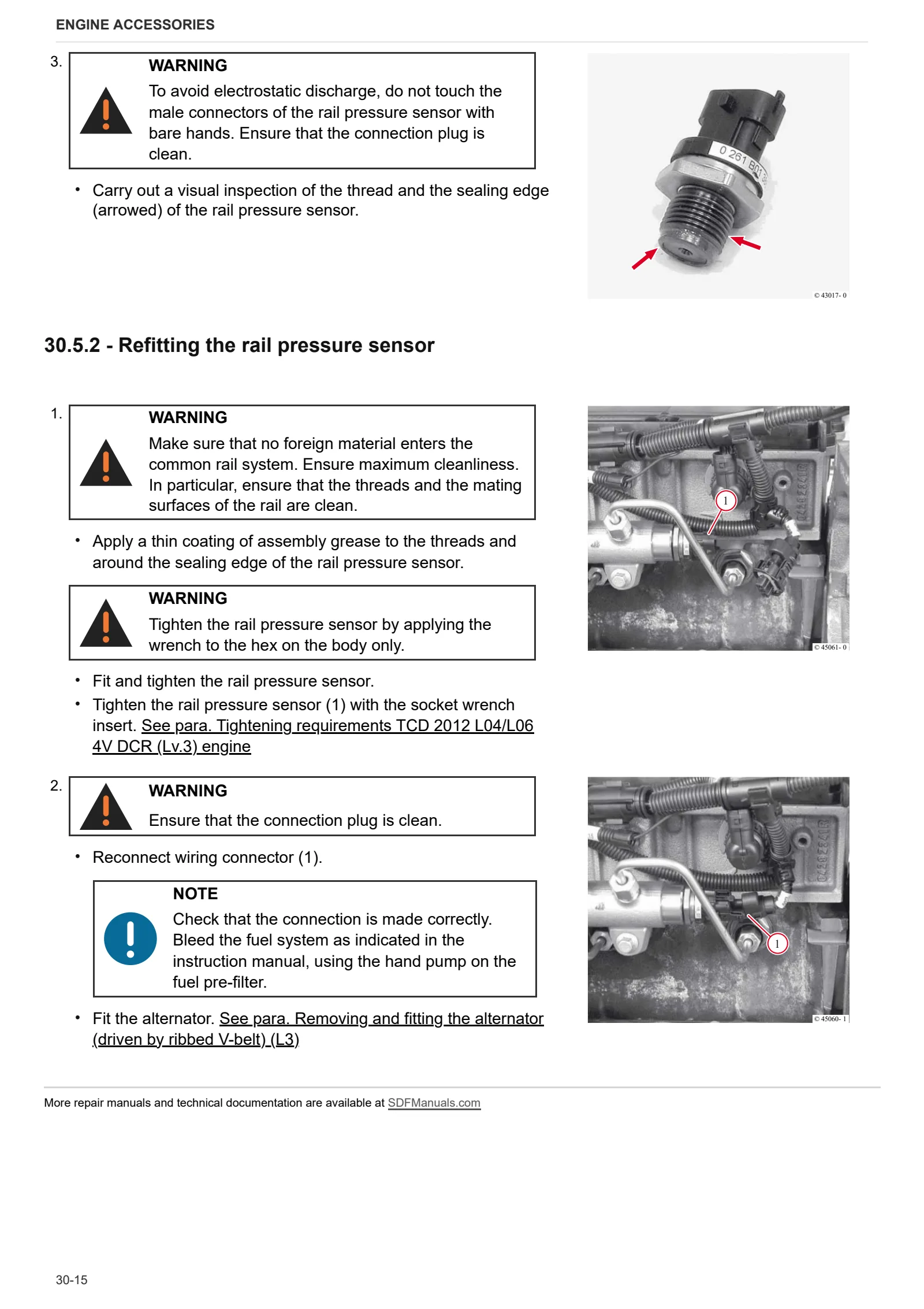
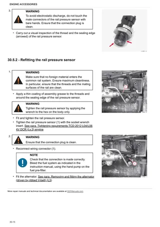
- Removal and refitting of the rail pressure sensor
- Removing and fitting the alternator (driven by ribbed V-belt) (L3)
- Disassembly and assembly of the starter
- Remove and install the heating flange
- Removal and refitting of the supply air pressure/temperature sender
- Removing and installing the fuel supply pump
Hydraulic system
- Hydraulic circuit – Connection diagram
- Hydraulic circuit diagram – Version without “Lateral tilt”
- Hydraulic circuit diagram – Version with “Lateral tilt”
Electrical equipment
Components
- Engine control unit – Deutz EMR3
- 2.8519.074.0/10 – HLHP control unit
- 16050210 – “DAVID” CAN module
- A – Starting and charging
- B – Fuses
- C – Earths
- D – Intermediate connections
- E – On-board instruments and visual and audible indicators
- F – External lights
- G – Interior lights
- H – Electrical and manual controls
- I – Circuit breakers
- J – Relays
- K – Sensors and transmitters
- L – Electromagnets and solenoid valves
- M – Electrical/electronic devices, flasher units and timers
- N – Electric motors and actuators
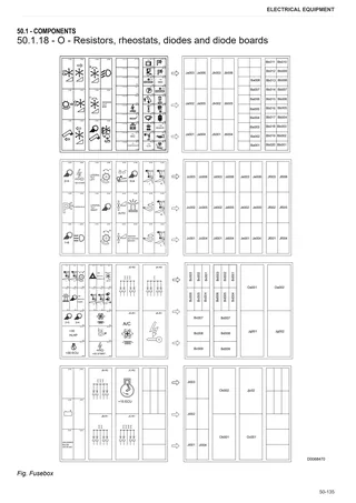
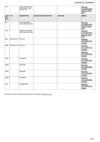
- O – Resistors, rheostats, diodes and diode boards
- P – Various services
- Q – Safety devices
- R – Diagnostics
- T – Power supply points
Systems
- S001 – Negatives
- S012 – Power supply (+15)
- S003 – Power supply (+30)
- S003A – Power feed (+30)
- S004 – Instrument panel
- S004B – Instrument panel
- S004A – Instrument panel
- S005 – Diagnostics – Accessories
- S005A – Diagnostics – accessories
- S006 – Lights and turn indicators
- S006A – Lights and turn indicators
- S006B – Lights and turn indicators
- S007 – Work lights
- S007A – Work lights
- S008 – Brakes
- S008A – Brakes
- S008B – Brakes
- S009 – Manual air conditioner
- S010 – Windscreen wipers
- S011 – Electronic engine governor
- S012 – Starting
- S013 – Transmission
- S014 – Can Bus
- S015 – Pick-up reel
- S015A – Pick-up reel
- S016 – Float and lateral rotation
- S016A – Float and lateral rotation
- S017 – Feed passage reverser
- S018 – Threshing unit
- S019 – Straw walker
- S020 – Sieve grain loss
- S021 – Straw chopper
- S022 – Grain tank
- S023 – Grain tank discharge pipe
- S023A – Grain tank discharge pipe
- S024 – Rape cutter
WIRING HARNESSES
- 0.015.5464.4/10 – Starter motor – Alternator
- 0.016.6228.4/20 – Front wiring loom
- 0.016.6228.4/30 – Front wiring loom
- 0.016.6229.4/10 – Solenoid valves block
- 0.016.6229.4/20 – Solenoid valves block
- 0.016.6230.4/10 – Frame
- 0.016.6230.4/20 – Frame
- 0.016.6231.4/20 – Rear wiring loom
- 0.016.6232.4/10 – Straw walker sensor
- 0.016.6234.4/20 – Roof
- 0.016.6235.4/10 – Roof lights
- 0.016.6236.4/20 – Fusebox ground
- 0.016.6236.4/30 – Fusebox ground
- 0.016.6237.4/10 – LH threshing drum door emergency switch
- 0.016.6238.4/10 – Grain tank
- 0.016.6239.4/10 – Fusebox
- 0.016.6239.4/20 – Fusebox
- 0.016.6239.4/30 – Fusebox
- 0.018.3464.4/10 – Straw chopper
- 0.017.4700.4/10 – Grain tank work lights
- 0.017.5023.4 – LH rear light
- 0.017.5023.4 – RH rear light
- 0.017.5623.4 – Front handrail work lights
- 0.018.0154.4/10 – Header
- 0.018.0155.4/10 – License plate light
- 0.018.0156.4/20 – Side console
- 0.900.2053.1 – Climate control
- 0.019.0697.4 – Grounds
- 04214410 – Fuel injectors
- 04215317 – Engine control – Machine side
- 04216076 – Engine control – Engine side
- 04216250 – Starter motor control relay
- 06544695 – Power supply for feed passage reverser
- 16050274/10 Sieve work light
- 16056731/10 – Right hand outline marker lights
- 16056731/10 – Left hand outline marker lights
- 16062550 – Feed passage reverser
Calibrations and diagnostics
- SERDIA 2000 level III” software
- SERDIA – Diagnostic socket connection
- SDF Analyser – Diagnostic socket connection
- Fault diagnosis
- Alarms – Engine alarms list
- Alarms – HLHP alarms
- Engine ECU Alarms: SPN 000016-000175
- Engine ECU Alarms: SPN 000190-001188
- Engine ECU Alarms: SPN 001231-003520
- Engine ECU Alarms: SPN 003532-005763
- Engine ECU Alarms: SPN 520521-523632
- Engine ECU Alarms: SPN 523633-523918
- Engine ECU Alarms: SPN 523919-524030
- Engine ECU Alarms: SPN 524031-524108
- Engine ECU Alarms: SPN 524109-524267
Service Info
HB – AXLES
- Adjusting rear axle toe angle
HH – ELECTRICAL SYSTEM
- Linear actuator
HL – CLEANER UNIT
- Straw walker supports assembly procedure
HM – GRAIN TANK / ELEVATOR
- Elevator and head chain tensioning