Document overview
Workshop Manual for DEUTZ FAHR 3045 E → NNZMW002V0BD50001 from the Series 3E (STAGE 5) family. Digital PDF in English with 623 pages.
The corresponding English table of contents contains 42 sections and 209 individual topics.
Main sections included
- Introduction
- Safety
- Technical characteristics
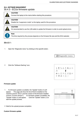
- Calibrations and electronic diagnosis
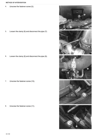
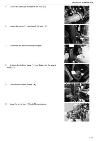
- Method of intervention
- Wiring diagrams
- Service Info
Document details
- Brand: DEUTZ FAHR
- Family: Series 3E (STAGE 5)
- Model: 3045 E
- Starting serial number: NNZMW002V0BD50001
- Document type: Workshop Manual
- Language: English
- Pages: 623
- File size: 225.93 MiB
- Format: Digital PDF download
Compatibility
Before purchasing, verify that your machine model and reference code match DEUTZ FAHR 3045 E → NNZMW002V0BD50001.
Complete table of contents
Introduction
- Tightening torques
- Pump tightening torques
- Wheel nut/screw tightening torques
- Tightening torques for nuts and bolts of electrical connections
- Installation of solenoid valves and cartridge valves
- Installation of quick couplers
- Units of measurement and conversion factors
Safety
Preface
- Important notes concerning safety
Important safety information
- Recognising hazards
- Indications for persons in contact with the tractor
Safety rules
- Risks during tractor preparation
- Risks during maintenance
- Work on machine systems
- Special disassembly/assembly/inspection procedures
Safety pictograms
- Replacing safety pictograms
Environmental risks
- Hazards associated with the operating environment
Technical characteristics
Engine
- General information
- Tightening Torques
- Technical information
- Lubrificating oil and fuel specification
- Warning
Engine accessories
- Starter motor
Transmission
- Four-wheel drive engagement assembly
Rear axle
- Brakes and rear axle assembly
- Rear differential assembly
Front axle
- Special tools
- Safety precautions
- Maintenance & lubrication
- Exploded view
- Maintenance Points
Hydraulic system
- Hydraulic circuit
- 4-way remote control valve
- Hydrostatic steering
Rear lift
- Rear lift
Calibrations and electronic diagnosis
Diagnostic tools
- D-TECH App
- D-Tech and diagnostic ports
Commissioning and calibrating the tractor
- Commissioning procedure (EOL)
- Cluster configuration
- Measurement unit
- Wheel parameter
- Throttle setting procedure
- Tyre type
ECU alarms
- SDF Severity of alarms
- ECU ALARMS
Software management
- ECUs
- On-board instruments (Cluster/Display) flashing
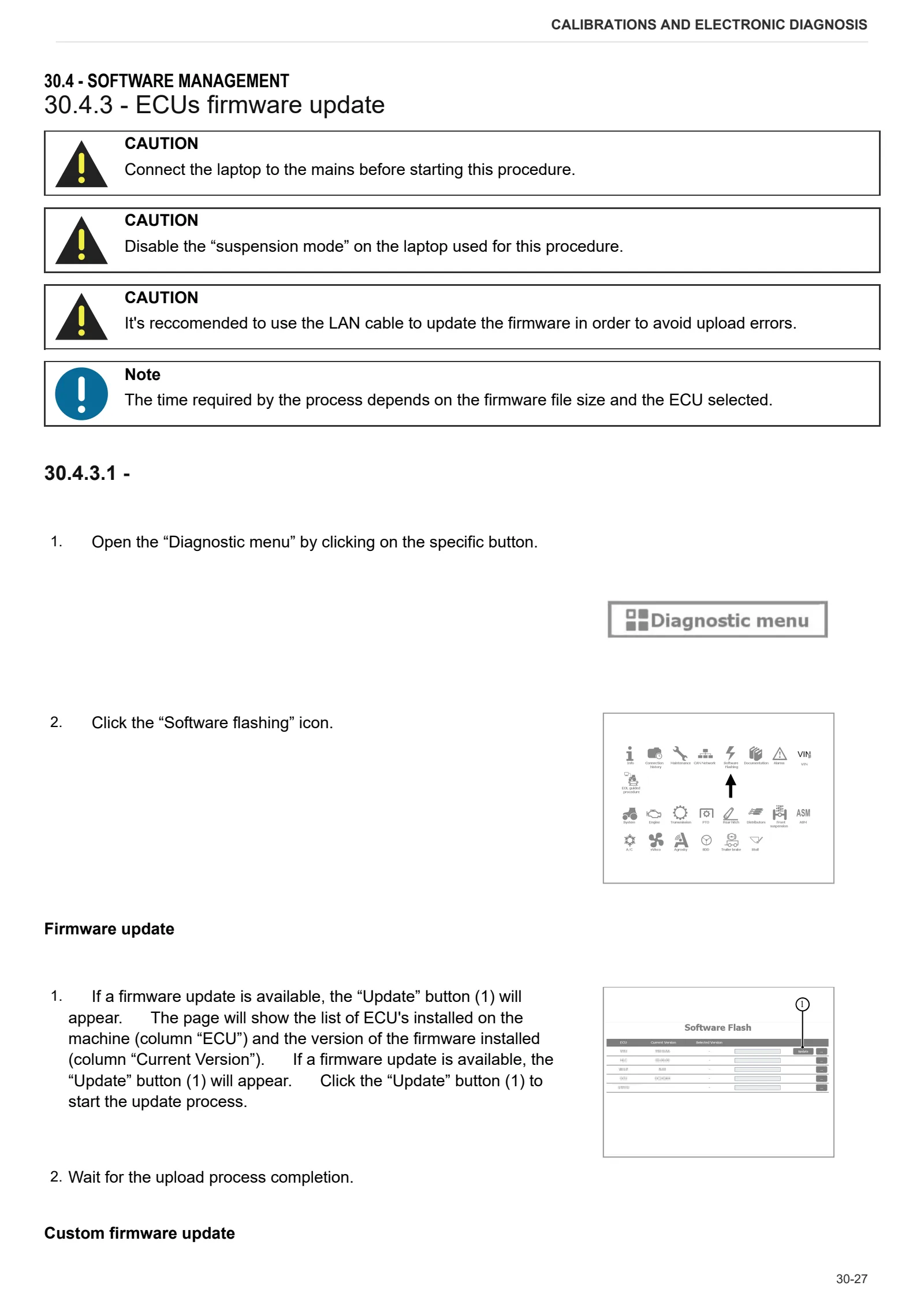
- ECUs firmware update
Method of intervention
- Special Tool
- Special tools
B0 – Engine
- S/R Cylinders block and liners
- S/R Flyweel
- S/R Crankshaft assembly
- S/R Piston and connecting rods
- S/R Timing case cover
- S/R Rocket shaft assembly
- S/R Valve springs
- S/R Timing case cover and drive
- S/R Cyilinder head cover
- Check & adjust valve tip clearance
- S/R Cylinder head assembly
- S/R Oil pump
- S/R Sump
- Fuel system layout
- S/R High pressure pump
- S/R Water pump
- S/R Inlet mainfold
- S/R Turbocharger
- S/R Alternator
- Separating the complete engine
- Separating the engine from the transmission
- S/R Injector
- S/R Oil filter
C0 – Engine accessories
- S/R Fan belt
- Replacing the coolant
- Complete radiator-heat exchanger pack
- Expansion tank
- Engine fan
- Air filter
- Bleeding the fuel circuit
- S/R Fuel filter element
- Diesel fuel tank
- S/R Starter motor
- S/R Exhaust manifold
- Drain pipe
- Intermediate manifold
- Electrical & electronic control system
D0 – Transmission
- Draining and filling the transmission oil
- Clutch
- Clutch plate wear check
- Disassembly of the gearbox input shaft
- Pressure plate assembly
- Shimming the bearing on the secondary shaft and the gears on the primary shaft
- Disassembly of the main shaft
- Disassembly of the secondary shaft
- Separating front gearbox housing from rear gearbox housing
- Gear lever cover
- Gear lever cover
- Gear shifter rods and fork assembly
- Conical screw assembly
- Internal range reduction gear controls
- Rear pinion casing
- PTO output shaft
- 4WD shaft in transmission
E0 – Rear axle
- Axle casing
- Disassembling rear axle
- Right-hand rear axle
- Left-hand rear axle
- Disassembling the planetary gear unit
- Rear differential
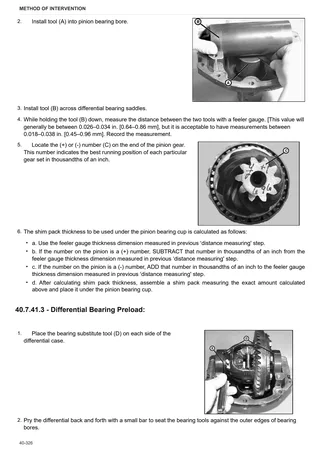
- Adjusting the bevel gear set and the rear differential
- Correct assembly of differential pins
- Brake carriers
- Removing the rear differential
- Rear differential lock control fork
- Bleeding air from the hydraulic brake system
- Rear brake discs
F0 – Front axle
- Pinion-differential assembly
- Carrier with front axle
- Front axle
- Front axle adjusting endfloat
- Steering cylinders
- Disassembling the steering cylinder
- Complete steering knuckle housing
- Adjusting bearing preload
- Differential assembly
- Assembly and adjustment of the front differential of SDF axles
- Differential lock
- 4WD shaft
- Adjustment of the bevel gear set
- Removing bevel gear set
- Adjustment of the differential preload
- Disassembly of the differential
- Differential locking device adjustment
- Adjusting pinion position
- Adjusting pinion/crown wheel backlash
- Adjusting pinion bearing preload
- Wheel hub bearing shims
- Planetary reduction gearbox
- Disassembly of the planetary reduction gearbox
- Front brake discs
- Front axle brake piston
- Front axle
- Differential assembly adjustment
- Steering Cylinder Removal
- Tie Rod Removal
- Drain Plug Removal
- Final drive cover disassembly
- Final drive cover installation
- Drop shaft disassembly
- Drop shaft assembly & installation
- Knuckle housing removal
- Knuckle housing installation
- Face seal installation
- Shoulder housing removal & disassembly
- Shoulder housing assembly
- Carrier removal & disassembly
- Carrier assembly & installation
- Wheel end installation
- Tie Rod Installation
- Steering cylinder installation
- Toe-in adjustment
- Assemble Rear Trunnion
- Assemble Front Trunnion
- Axle Installation & End Play Adjustment
- Driveshaft & Hydraulic Line Installation
G0 – Bodywork – Cab – Platform
- Engine hood
- Lower hood guard
- Platform
- Underseat plate
- Cab access steps
- Rear mudguards
- Front mudguard
- Instrument panel
- Dashboard
- Lower dashboard guard
- Upper dashboard guard
- Guard panels
- Roof
- Driver seat
- Steering wheel
- Roll bar
H0 – Hydraulic system
- Hydrostatic steering (orbitrol)
- Rear auxiliary utility distributor
L0 – Electrical system
- Battery
R0 – Rear lift
- Rear lift
- Adjustment of the rear lift
S0 – Wheels
- Front Wheels
- Rear wheels
V0 – Ballast – towing hitches
- Front ballasts and support
- Draw-bar
Wiring diagrams
Wiring harnesses
- Wiring looms
- W-TECH – ELECTRICAL SECTION
Service Info
A0 – TRACTOR
- Diagnostics 2026 subscription
- After-sales 2026 subscription
- SERVICE NEWS RESEARCH GUIDE
- Diagnostics 2025 subscription
- After-sales 2025 subscription
- Diagnostics 2024 subscription
- After-sales 2024 subscription
B0 – ENGINE
- FARMotion seal ring leakage
C0 – ENGINE ACCESSORIES
- Diagnostic protocol – AdBlue – Float level unit
- Filter and prefilter tool p/n 5.9035.865.0
F0 – FRONT AXLE
- Bevel gear set loosing screws
H0 – HYDRAULIC AND PNEUMATIC SYSTEM|
- Hydraulic CUNA trailer braking kit (ITALY)
- Single connection hydraulic braking kit availability update – only for EUROPEAN market
L0 – ELECTRIC AL SYSTEM
- Electronic diagnosis of Simpson engines (Turkish market)
- PTO switch not working
V1 – AFTERMARKET KITS
- Check correct installation of braking KIT
- Instructions for kit aftersales