

Document overview
Digital Workshop Manual documentation for model DEUTZ FAHR AGROLUX 90 → D13P874AVT1001 from the Agrolux family. Language: English; 962 pages.
The corresponding English table of contents contains 36 sections and 302 individual topics.
Main sections included
- Introduction
- Safety
- Technical characteristics
- Method of intervention
- Wiring diagrams
- Service Info
Document details
- Brand: DEUTZ FAHR
- Family: Agrolux
- Model: AGROLUX 90
- Starting serial number: D13P874AVT1001
- Document type: Workshop Manual
- Language: English
- Pages: 962
- File size: 119.08 MiB
- Format: Digital PDF download
Compatibility
Before purchasing, verify that your machine model and reference code match DEUTZ FAHR AGROLUX 90 → D13P874AVT1001.
Complete table of contents
Introduction
- Tightening Torques
- Tightening torques for nuts and bolts of electrical connections
- Wheel rim to hub screws and nuts tightening torques
- Pump tightening torques
- Installation of quick couplers
Safety
Preface
- Important notes concerning safety
Important safety information
- Recognising hazards
- Indications for persons in contact with the tractor
Safety rules
- Risks during tractor preparation
- Risks during maintenance
- Work on machine systems
- Special disassembly/assembly/inspection procedures
Safety pictograms
- Replacing safety pictograms
Environmental risks
- Hazards associated with the operating environment
Technical characteristics
Engine
- Identification of the engine type and serial number position – Europe version
- Identification of the engine type and serial number position, EPA version
- Engine monobloc technical data
- Crankshaft technical data
- Crankshaft technical data
- Crankshaft technical data
- Piston technical data – Piston rings
- Piston technical data – Piston rings
- Piston technical data – Piston rings
- Piston technical data – Piston rings
- Piston technical data – Piston rings – 120-135-150 hp versions
- Piston technical data – Piston rings – 160-180-200 hp versions
- Connecting rod technical data – for pistons without cooling chamber
- Connecting rod technical data – for pistons with cooling chamber
- Camshaft technical data – static advance of 13°
- Camshaft technical data – static advance of 13°
- Camshaft technical data – static advance of 16°
- Camshaft technical data – static advance of 16°
- Timing gears technical data
- Counter-rotating weights technical data
- Technical data and dimensions of valves – valve springs
- Technical data and dimensions of valves – valve springs
- Technical data and dimensions of cylinder heads – valve guides – valve seats
- Technical data and dimensions of cylinder heads – valve guide – valve seats
- Technical data and dimensions of rocker arms – rocker shafts – tappets
- Technical data and dimensions of rocker arms – rocker shafts – tappets
- Pumps
- Identification of the injector type
- Fuel injector technical data
Transmission
- Transmission
- Rear PTO
- 2 speed PTO and groundspeed PTO
Front axle
- Front axle
Hydraulic system
- Hydraulic system
- Steering circuit pump – lift circuit pump
- Power steering valve
- Remote control valve
- Remote control valve – USA version
- Braking system
- Trailer braking valve
Method of intervention
B0 – Engine
- ENGINE
- ENGINE
- Preliminary and final operations
- Final engine checks
- Checking engine block
- Crankshaft
- Crankshaft checks
- Crankshaft checks
- Flywheel checks
- Renewal of crankshaft rear oil seal
- Pistons and cylinder liners
- Pistons and rings check
- Cylinder liners check
- Check connecting rods – gudgeon pins – rod cap screws
- Camshaft
- Camshaft
- Camshaft checks
- Timing gear checks
- Adjusting timing gears backlash
- Valve timing
- Counter-rotating weights
- Overhaul of counter-rotating weights assembly
- Counter-rotating weight checks
- Valves check
- Valve seats check
- Valves sealing check
- Valve clearance adjustment
- Valve guides check and renewal
- Inspecting the rocker arms and rocker shafts
- Cylinder heads
- Cylinder head disassembly – 2-valve version
- Cylinder head disassembly – 3-valve version
- Valve springs check
- Heat exchanger
- Disassembly of the heat exchanger
- Lubrication pump
- Lubrication pump disassembly
- Lubrication pump disassembly
- Oil sump
- Oil sump
- Injection pumps, actuator and fuel supply
- Injection pump timing
- Injector assembly
- Checking injectors protrusion – Renewal of copper bushes
- Injector checks
- Injection pumps control rod
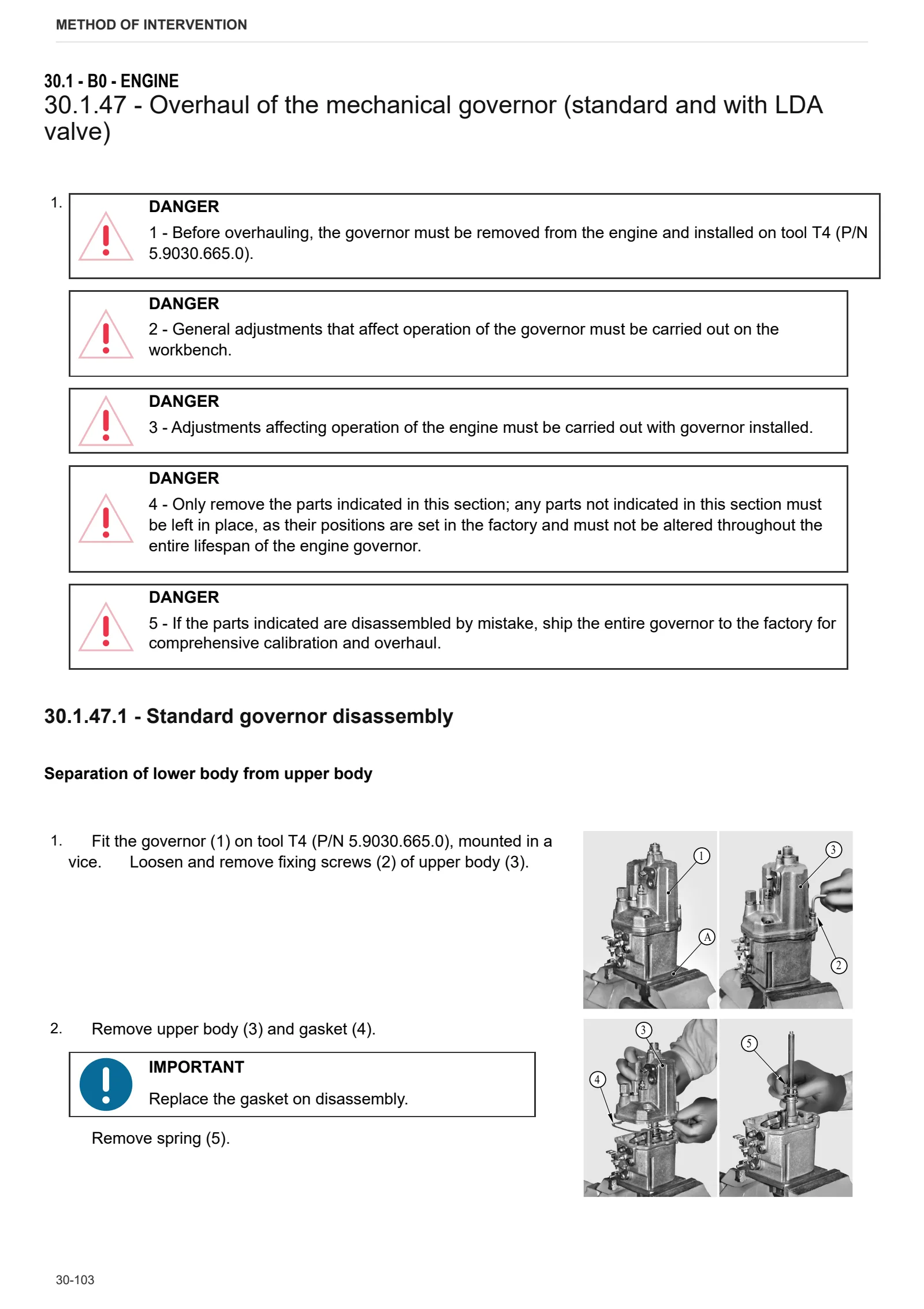
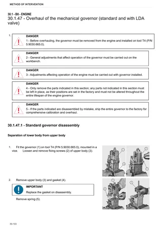
- Overhaul of the mechanical governor (standard and with LDA valve)
- Overhaul of the mechanical governor gear
- Adjusting electronic actuator
- Power adjustment data table
- Mechanical governor drive unit and electronic governor support
- Mechanical governor drive unit and electronic governor support
- Water pump
- Water pump
- Thermostat
- Thermostat
- Checking the thermostat
- Cooling and intake ducts
C0 – Engine accessories
- Fuel tank
D0 – Transmission
- Clutch
- Release bearing
- Disassembly of the parking brake
- Clutch housing
- Gearbox and shuttle assembly – 4-speed version
- Disassembly of gearbox and shuttle assembly – 4-speed version
- Disassembly of the shuttle and underdrive shaft
- Disassembly of the main shaft
- Disassembly of the secondary shaft
- Gearbox and shuttle assembly – 5-speed version
- Disassembly of gearbox support and gear selector rods
- Disassembly of the shuttle shaft
- Disassembly of the main shaft
- Disassembly of the secondary shaft
- Disassembly of gearbox and shuttle assembly – 5-speed version
- Range gearbox and rear differential assembly
- Disassembly of the bevel pinion
- Disassembly of the 4WD engagement device
- Disassembly of 4WD output shaft and parking brake
- Bevel gear pair
- Disassembly of the pump drive PTO
- Disassembly of the pump drive PTO
- PTO input shaft
- Disassembly of the PTO input shaft
- PTO clutch
- Disassembly of the PTO clutch
- Disassembly of the groundspeed PTO engagement device
- Disassembly of the groundspeed PTO output shaft
E0 – Rear axle
- Renewal of rear axle brake discs
- Disassembly of the rear axle brake piston
- Braking circuit
- Right hand rear axle
- Left hand rear axle
- Disassembly of the rear axle
- Disassembly of the planet carrier
- Differential
- Disassembly of the differential
F0 – Front axle
- 4WD shaft
- Front support
- Front axle – 4WD
- Adjustment of front axle play – 4WD
- Steering cylinders
- Disassembly of the steering cylinder
- Planetary reduction gear
- Disassembly of the final drive unit
- Steering knuckle housing and half-shaft
- Adjustment of steering knuckle housing and half shaft bearings preload
- PINION-DIFFERENTIAL ASSEMBLY
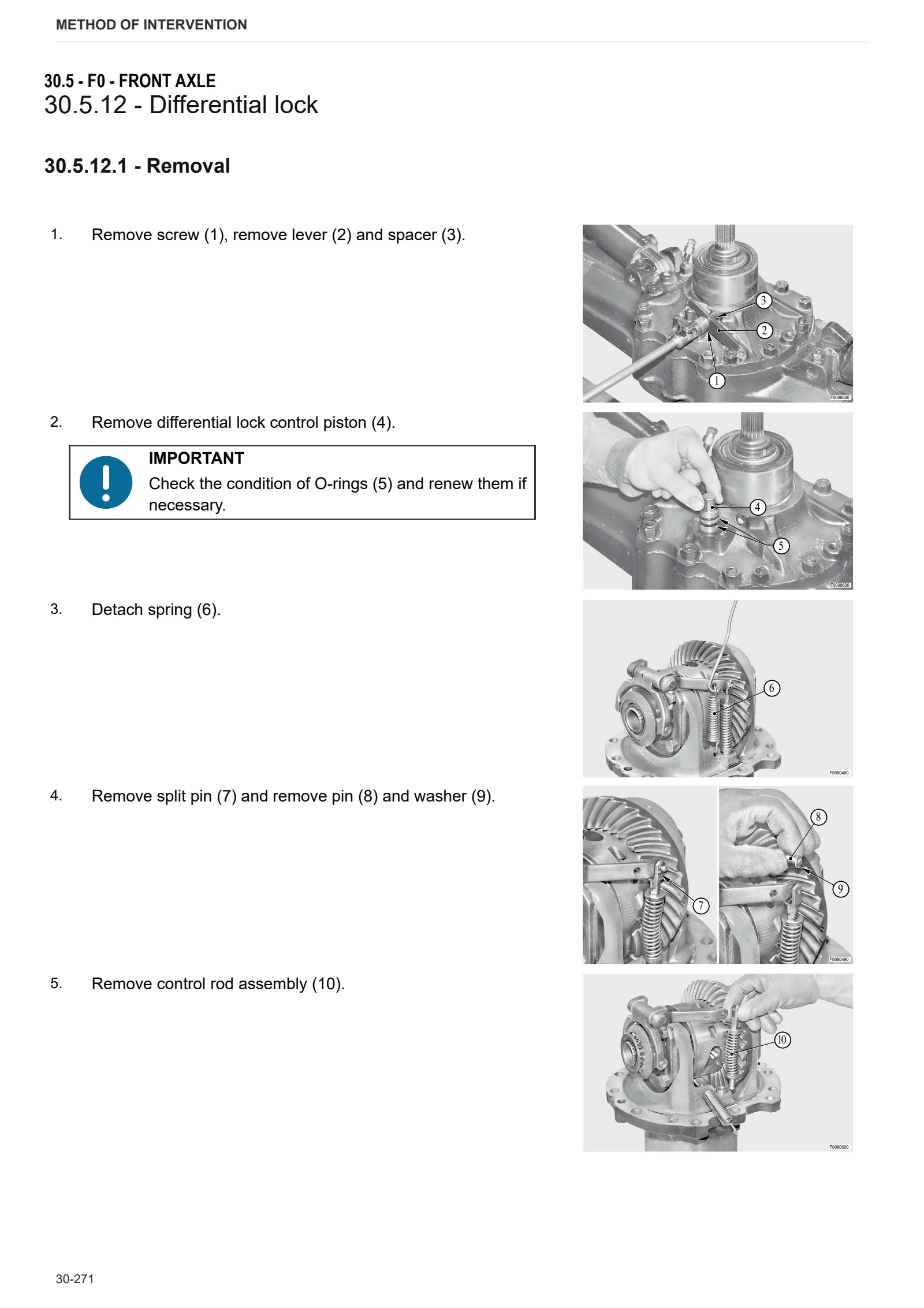
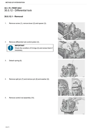
- Differential lock
- Differential locking device adjustment
- Bevel gear pair
- Adjustment of the bevel gear pair
- Differential
- Front axle – 2WD
- Front wheel hub
- Front wheel hub/spindle assembly
- Steering cylinders
- Disassembly of the steering cylinders
- Disassembly of steering arms
- Front brake discs
- Disassembly of the front axle brake piston
G0 – Bodywork – Cab – Platform
- Front hood and side panels
- Instrument panel
- Safety frame
- Safety frame support
- Safety roll bar – Folding version
- Safety roll bar support
- Clutch master cylinder
- Clutch piston
- Clutch control circuit
- Brake master cylinders
- Fenders
- Seat support
- Adjustment of the control levers
H0 – Hydraulic system
- Power steering valve
- Calibration of the power steering pressure relief valve
- Power steering disassembly
- Remote control valve
- Remote valve – Standard version
- Remote control valve – USA version
- Remote valve – USA
- Pump for hydraulic lift and remote control valve
- Power steering pump
L0 – Electrical system
- Battery
R0 – Rear lift
- Lift
- Disassembly of the lift
- Lift cylinder disassembly
- Replacing bushes
- Disassembly of the lift control valve
- Mechanical draft sensor
- Mechanical draft sensor disassembly
- 3-point linkage
S0 – Wheels
- Front wheels – 4WD version
- Front wheels – 2WD version
- Rear wheels
Wiring diagrams
Introduction
- Introduction
- Basic electronics for mechanics (1/2)
- Basic electronics for mechanics (2/2)
- Electrical and electronic components (1/2)
- Electrical and electronic components (2/2)
Components
- A – Starting and charging
- B – Valves and fuses box
- C – Earths
- D – Intermediate connections
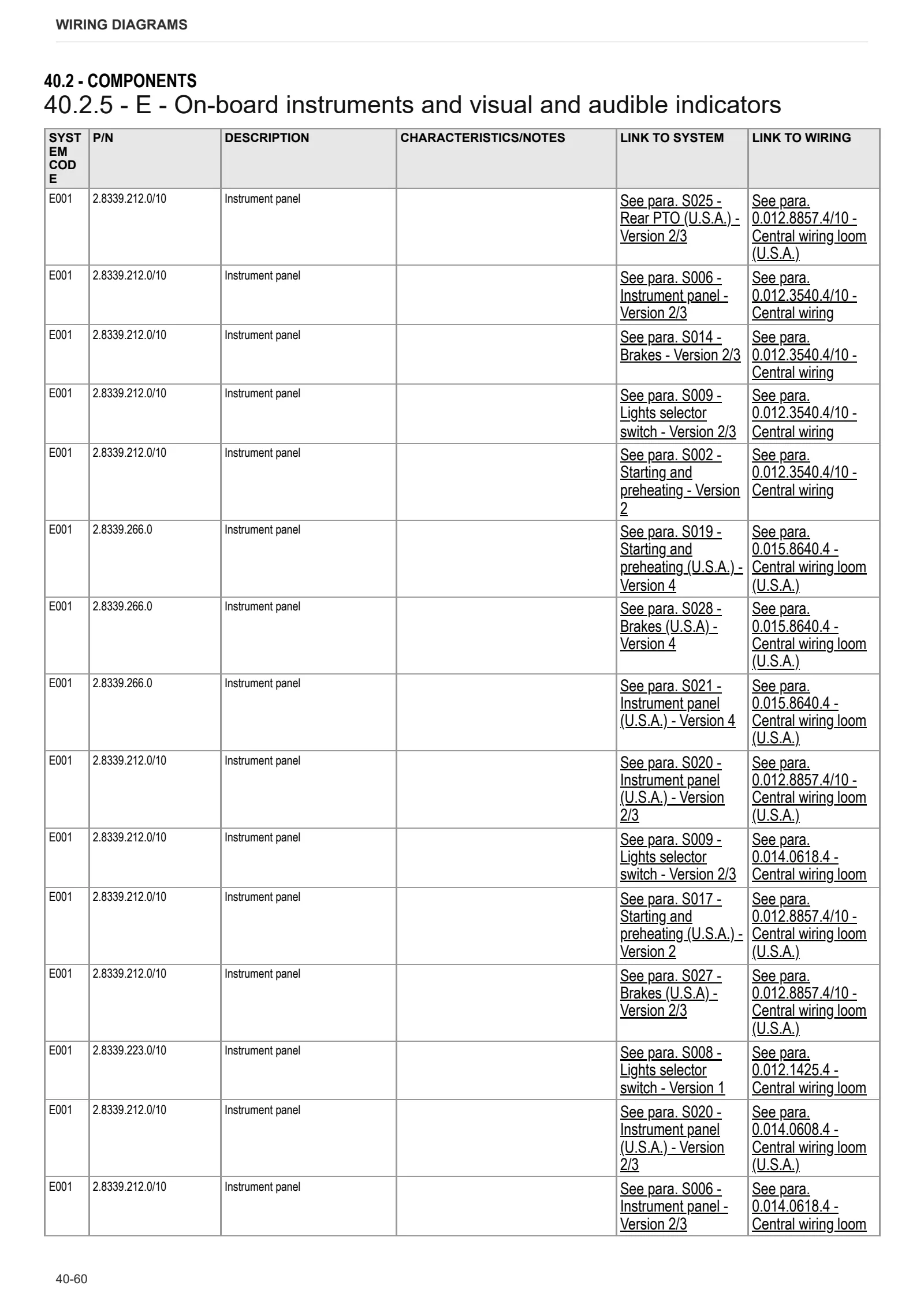
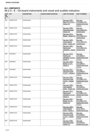
- E – On-board instruments and visual and audible indicators
- F – External lights
- H – Electrical and manual controls
- I – Circuit breakers
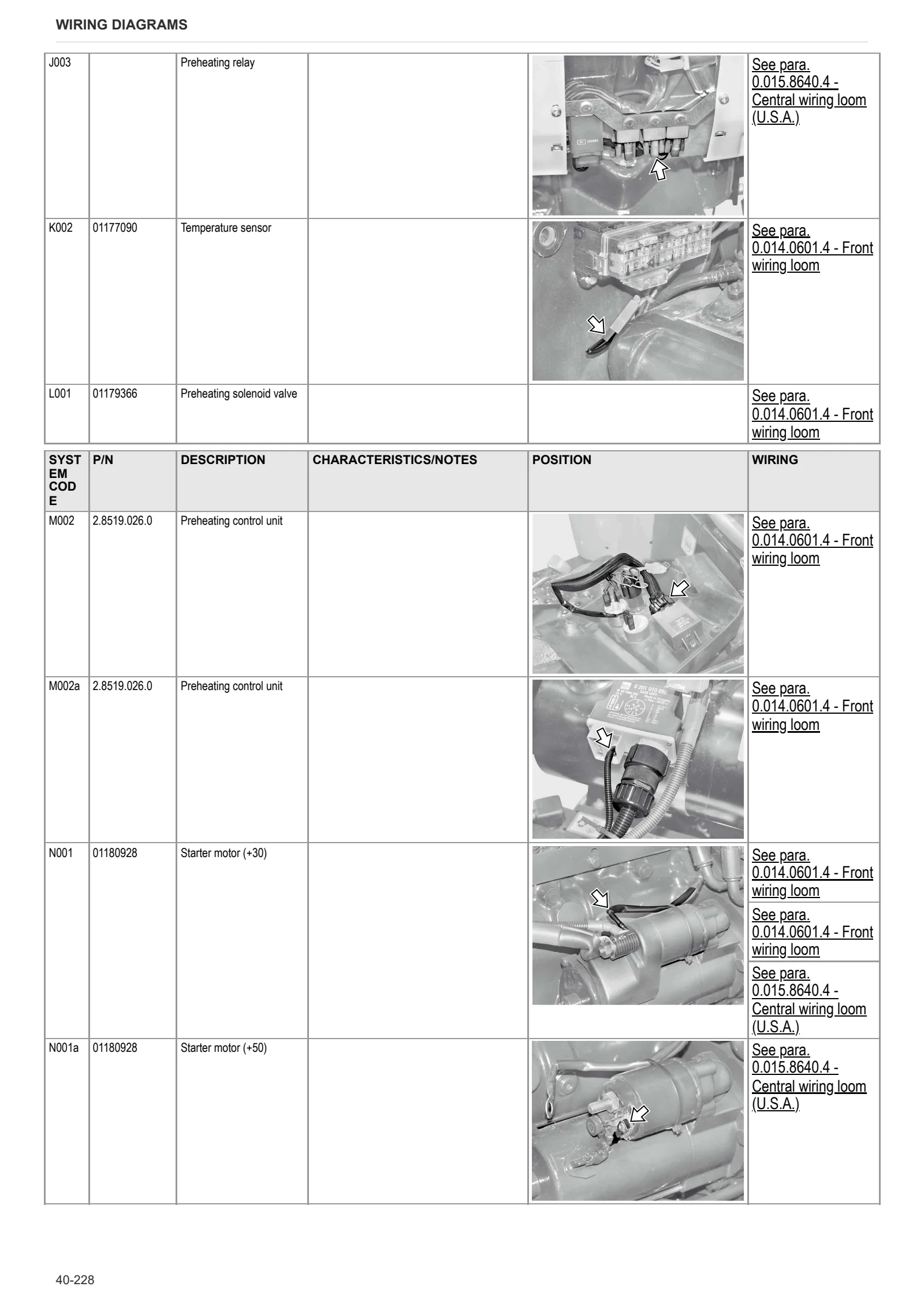
- J – Relays
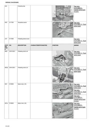
- K – Sensors and transmitters
- L – Electromagnets and solenoid valves
- M – Electrical/electronic devices, flasher units and timers
- N – Electric motors and actuators
- O – Resistors, rheostats, diodes and diode boards
- P – Various services
- T – Power supply points (+15 o +30)
Systems
- How to consult the system diagrams
- Descriptions of the different versions
- Earthing points
- S001 – Starting and preheating – Version 1
- S002 – Starting and preheating – Version 2
- S003 – Starting and preheating – Version 3
- S004 – Starting and preheating – Version 4
- S005 – Instrument panel – Version 1
- S006 – Instrument panel – Version 2/3
- S007 – Instrument panel – Version 4
- S008 – Lights selector switch – Version 1
- S009 – Lights selector switch – Version 2/3
- S010 – Instrument panel – Version 4
- S011 – +30 Positives
- S012 – +15 Positives
- S013 – Brakes – Version 1
- S014 – Brakes – Version 2/3
- S015 – Brakes – Version 4
- S016 – Accessories
- S017 – Starting and preheating (U.S.A.) – Version 2
- S018 – Starting and preheating (U.S.A.) – Version 3
- S019 – Starting and preheating (U.S.A.) – Version 4
- S020 – Instrument panel (U.S.A.) – Version 2/3
- S021 – Instrument panel (U.S.A.) – Version 4
- S022 – Lights selector switch (U.S.A.) – Version 2/3
- S023 – Lights selector switch (U.S.A.) – Version 4
- S024 – +15 Positives (U.S.A.)
- S025 – Rear PTO (U.S.A.) – Version 2/3
- S026 – Rear PTO (U.S.A.) – Version 4
- S027 – Brakes (U.S.A) – Version 2/3
- S028 – Brakes (U.S.A) – Version 4
Wiring harnesses
- 0.011.8388.4/10 – Roll bar lights wiring loom
- 0.012.1414.4 – Front wiring loom
- 0.012.1425.4 – Central wiring loom
- 0.012.1426.4/20 – Rear wiring loom
- 0.012.2096.4 – Rear lights wiring loom
- 0.012.3540.4/10 – Central wiring
- 0.012.3634.4/10 – Rear wiring loom
- 0.012.3825.4 – Roll bar lights wiring loom (U.S.A.)
- 0.012.8857.4/10 – Central wiring loom (U.S.A.)
- 0.012.8858.4/10 – Rear wiring loom (U.S.A.)
- 0.012.8860.4 – Rear lights wiring loom (U.S.A.)
- 0.014.0601.4 – Front wiring loom
- 0.014.0608.4 – Central wiring loom (U.S.A.)
- 0.014.0616.4 – Central wiring loom
- 0.014.0618.4 – Central wiring loom
- 0.015.8640.4 – Central wiring loom (U.S.A.)
Service Info
A0 – TRACTOR
- Diagnostics 2026 subscription
- After-sales 2026 subscription
- SERVICE NEWS RESEARCH GUIDE
- Diagnostics 2025 subscription
- After-sales 2025 subscription
- Diagnostics 2023 subscription
- Diagnostics 2024 subscription
- Diagnostics 2022 subscription
- Diagnostics 2021 subscription
- After-sales 2024 subscription
- After-sales 2023 subscription
- After-sales 2022 subscription
- After-sales 2021 subscription
- After-sales 2019 subscription
- Technical Documentation DVD 03/2010
- Diagnostics – 2020 subscription
- After-sales – 2020 subscription
- SDF Parts and SDF Service DVDs 05/2014 version 25
B0 – ENGINE
- Deutz AG engine oil specifications
C0 – ENGINE ACCESSORIES
- Diagnostic protocol – AdBlue – Float level unit
- Filter and prefilter tool p/n 5.9035.865.0
F0 – FRONT AXLE
- Check the front axle steering knuckles for wear
- Steering behavior check procedure
G0 – BODYWORK – CAB
- Air conditioning system recharging
H0 – HYDRAULIC AND PNEUMATIC SYSTEM|
- Hydraulic CUNA trailer braking kit (ITALY)
- Single connection hydraulic braking kit availability update – only for EUROPEAN market
- L0 – ELECTRIC AL SYSTEM