Document overview
Workshop Manual PDF for DEUTZ FAHR 7230 TTV Agrotron → WSXV870200LD50010, Series 7 Agrotron TTV (STAGE 3B) family. Document language: English; 2,339 pages.
The corresponding English table of contents contains 54 sections and 713 individual topics.
Main sections included
- Introduction
- Safety
- Technical characteristics
- Calibrations and electronic diagnosis
- Method of intervention
- Wiring diagrams
- Service Info
Document details
- Brand: DEUTZ FAHR
- Family: Series 7 Agrotron TTV (STAGE 3B)
- Model: 7230 TTV Agrotron
- Starting serial number: WSXV870200LD50010
- Document type: Workshop Manual
- Language: English
- Pages: 2,339
- File size: 257.44 MiB
- Format: Digital PDF download
Compatibility
Before purchasing, verify that your machine model and reference code match DEUTZ FAHR 7230 TTV Agrotron → WSXV870200LD50010.
Complete table of contents
Introduction
- Tightening torques
- Tightening torques for nuts and bolts of electrical connections
- Wheel nut/screw tightening torques
- Units of measurement and conversion factors
Safety
Preface
- Important notes concerning safety
Important safety information
- Recognising hazards
- Indications for persons in contact with the tractor
Safety rules
- Risks during tractor preparation
- Risks during maintenance
- Work on machine systems
- Special disassembly/assembly/inspection procedures
Safety pictograms
- Replacing safety pictograms
Environmental risks
- Hazards associated with the operating environment
Technical characteristics
Engine
- Motor description – construction type
- Engine description – Images of engine
- Engine description – Lubricant oil diagram
- Engine description – Fuel circuit diagram
- Engine description – Coolant diagram
- Engine description – Exhaust gas recovery
- Engine description – Exhaust gas after-treatment
- Engine description – Electrical/electronic system
- Use – Environmental conditions
- Use – First start-up
- Usage – Starting procedure
- Usage – Controlling engine operation
- Use – exhaust gas after-treatment systems
- Usage – Active regeneration
- Usage – Passive regeneration
- Use – Stop procedure
- Operating materials – lubricant oil
- Operating materials – Fuel
- Operating materials – Coolant
- Fluids – SCR reduction agent
- Maintenance – Maintenance schedule
- Care and maintenance work – Lubricant oil system
- Care and maintenance work – Fuel distribution system
- Care and maintenance – SCR
- Care and maintenance work – Cooling system
- Care and maintenance work – Engine cleaning
- Care and maintenance work – Intake system
- Care and maintenance work – Belt transmissions
- Care and maintenance – Adjustments and settings
- Care and maintenance work – Electrical system
- Malfunctions – Malfunction table
- Faults – Engine management
- Transport and storage – Transport
- Transport and storage – Transport and storage
- Technical data – Engine data and adjustment data
- Technical data – Tools
Engine accessories
- SCR system
- AdBlue level and temperature sensor
- AdBlue tank
- AdBlue® technical characteristics
- AdBlue Quality
- Pressure transducer (L3)
- Pressure sensor (L3)
- Temperature sender (L3)
- Temperature sender (L3)
- Temperature sender (L3)
- Temperature sender (L3)
- Speed indicator (L3)
- NOx sensor (L3)
- NOx sensor (L3)
- Removing and fitting fuel lines (fuel delivery pump – fuel control block) (L3)
- Fitting and removing the temperature sender (exhaust gas) (L3)
- Temperature sender (L3)
- Removing and fitting NOx sensor (L3)
- Temperature sender (exhaust gas) (L3)
Transmission
- Transmission (60 Km/h)
- Transmission (50 Km/h)
- System diagram
- Description of function
- Transmission control
Front axle
- Front axle
- Front axle – Version with disc brakes
Bodywork – Cab – Platform
- Air conditioning system
Hydraulic system
- Hydraulic system
- 45 cc variable displacement pump
- 63 cc variable displacement pump
- Hydraulic pump
- Load sensing valve, pressure cut-off valve
- Priority valve
- Pressure limiting valve
- Power steering
- Hydraulic front axle suspension
- Servo-brake valve for front axle
- Hydraulic trailer braking system – Italy version
- Hydraulic trailer braking system – Export version
- Steering gear pump – Version without compressor
- Steering gear pump – Version with compressor
- Braking system
- Master cylinder
- Remote control valve – 8-way version
- Ancillary utility distributor – 10-way version
- Remote control valve – 12-way version
- Remote control valve – 14-way version
- Air trailer braking system – Italy version
- Air trailer braking system – Export version
- Compressor
- Trailer air braking valve (2-way)
- Trailer air braking valve (1-way)
- Pilot solenoid valve for 1-way trailer air braking valve
Calibrations and electronic diagnosis
- Diagnostic sockets and connections
- ECU interrogation
Diagnostic tools
SDF Analyser
- SDF Analyser
Serdia 2010
- Safety-Hints
- Common Hints
- Common Hints – Start and Communication
- Common Hints – Disposability
- Introduction
- Error Hints (FAQ)
- Connection establishment
- Software handling
- Software handling – Topper elements
- Global Programfunctionality – Dataset management
- Global Programfunctionality – Error memory
- Global Programfunctionality – Graphical display
- Global Programfunctionality – Program adjustments
- UseCases EMR4
- Engine settings
- Adjustments engine speed – acceleration pedal
- CRT – TIER4 interim
- DPF – Burner – TIER4 interim
- SCR – TIER4 interim
- SCR service routines
- DPF service routines
- Service Routines DPF (DOC/SCR)
- Service-Cases
- Other
- UseCases EMR3
- UseCases EMR2
- Programm options
Diagnostic tool screens
- Electronic Control Units and CANBUS Network layout
Commissioning and calibrating the tractor
- Commissioning – Introduction (HLHP software version SC0119AB)
- Putting in service – Initialization of the HLHP control unit
- Putting into service – Model configuration
- Putting into service – Calibration of transmission
- Putting into service – P.T.O.
- Putting into service – ASM
- Putting into service – Lift
- Putting into service – Suspension
- Putting into service – System
- Putting into service – Distributors
- Putting into service – Engine
- Putting into service – Air conditioning
- Putting into service – Agrosky
- Putting into service – Semiactive cabine
- Putting into service – Alarms
ECU alarms
Engine alarms
- Engine ECU Alarms: SPN 000016-000175
- Engine ECU Alarms: SPN 000190-001188
- Engine ECU Alarms: SPN 001231-003520
- Engine ECU Alarms: SPN 003532-005763
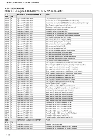
- Engine ECU Alarms: SPN 520521-523632
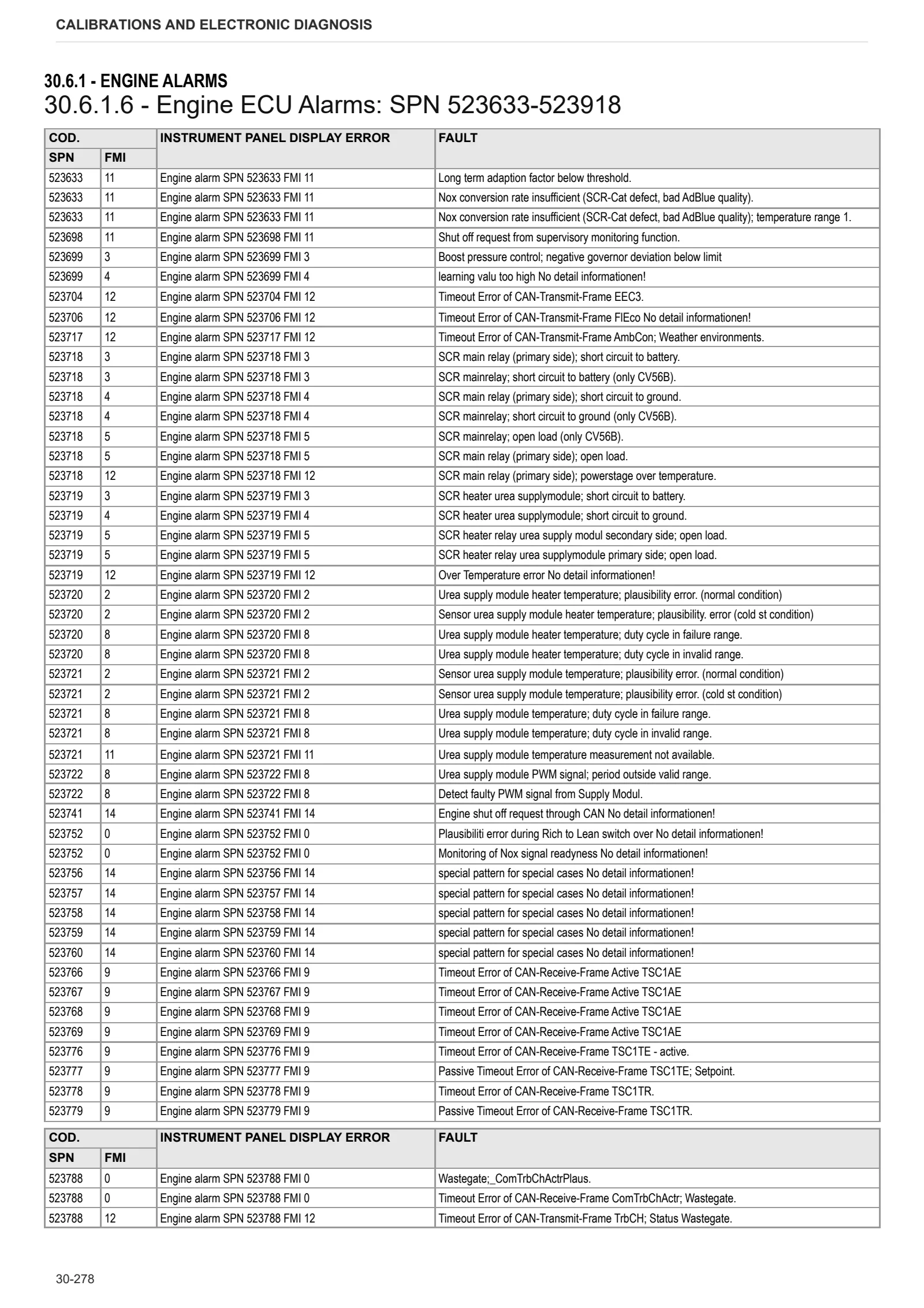
- Engine ECU Alarms: SPN 523633-523918
- Engine ECU Alarms: SPN 523919-524030
- Engine ECU Alarms: SPN 524031-524108
- Engine ECU Alarms: SPN 524109-524267
Transmission alarms
- Transmission alarms “FMGR” ECU
- Transmission alarms “SGR” ECU
- SGR ECU – Error 01
- SGR ECU – Error 02
- SGR ECU – Error 03
- SGR ECU – Error 05
- SGR ECU – Error 07
- SGR ECU – Error 08
- SGR ECU – Error 09
- SGR ECU – Error 0A
- SGR ECU – Error 0B
- SGR ECU – Error 0C
- SGR ECU – Error 0D
- SGR ECU – Error 0E
- SGR ECU – Error 0F
- SGR ECU – Error 10
- SGR ECU – Error 11
- SGR ECU – Error 12
- SGR ECU – Error 13
- SGR ECU – Error 14
- SGR ECU – Error 15
- SGR ECU – Error 16
- SGR ECU – Error 17
- SGR ECU – Error 18
- SGR ECU – Error 19
- SGR ECU – Error 1A
- SGR ECU – Error 1B
- SGR ECU – Error 1C
- SGR ECU – Error 1D
- SGR ECU – Error 1E
- SGR ECU – Error 1F
- SGR ECU – Error 20
- SGR ECU – Error 21
- SGR ECU – Error 22
- SGR ECU – Error 23
- SGR ECU – Error 24
- SGR ECU – Error 25
- SGR ECU – Error 26
- SGR ECU – Error 27
- SGR ECU – Error 28
- SGR ECU – Error 29
- SGR ECU – Error 2A
- SGR ECU – Error 2B
- SGR ECU – Error 2C
- SGR ECU – Error 2D
- SGR ECU – Error 2E
- SGR ECU – Error 2F
- SGR ECU – Error 30
- SGR ECU – Error 31
- SGR ECU – Error 32
- SGR ECU – Error 33
- SGR ECU – Error 34
- SGR ECU – Error 35
- SGR ECU – Error 36
- SGR ECU – Error 38
- SGR ECU – Error 39
- SGR ECU – Error 3C
- SGR ECU – Error 3D
- SGR ECU – Error 3F
- SGR ECU – Error 40
- SGR ECU – Error 41
- SGR ECU – Error 42
- SGR ECU – Error 43
- SGR ECU – Error 44
- SGR ECU – Error 45
- SGR ECU – Error 46
- SGR ECU – Error 47
- SGR ECU – Error 48
- SGR ECU – Error 49
- SGR ECU – Error 4A
- SGR ECU – Error 4B
- SGR ECU – Error 4C
- SGR ECU – Error 4D
- SGR ECU – Error 4E
- SGR ECU – Error 4F
- SGR ECU – Error 50
- SGR ECU – Error 51
- SGR ECU – Error 52
- SGR ECU – Error 53
- SGR ECU – Error 54
- SGR ECU – Error 55
- SGR ECU – Error 56
- SGR ECU – Error 57
- SGR ECU – Error 58
- SGR ECU – Error 59
- SGR ECU – Error 5A
- SGR ECU – Error 5C
- SGR ECU – Error 5D
- SGR ECU – Error 5E
- SGR ECU – Error 5F
- SGR ECU – Error 60
- SGR ECU – Error 61
- SGR ECU – Error 62
- SGR ECU – Error 63
- SGR ECU – Error 68
- SGR ECU – Error 69
- SGR ECU – Error 6A
- SGR ECU – Error 6B
- SGR ECU – Error 6C
- SGR ECU – Error 70
- SGR ECU – Error 71
- SGR ECU – Error 72
- SGR ECU – Error 73
- SGR ECU – Error 74
- SGR ECU – Error 75
- SGR ECU – Error 76
- SGR ECU – Error 78
- SGR ECU – Error 79
- SGR ECU – Error 7A
- SGR ECU – Error 7B
- SGR ECU – Error 7C
- SGR ECU – Error 7D
- SGR ECU – Error 7E
- SGR ECU – Error 7F
- SGR ECU – Error 82
- SGR ECU – Error 83
- SGR ECU – Error 84
- SGR ECU – Error 85
- SGR ECU – Error 86
- SGR ECU – Error 87
- SGR ECU – Error 88
- SGR ECU – Error 90
- SGR ECU – Error 91
- SGR ECU – Error 92
- SGR ECU – Error 93
- SGR ECU – Error 94
- SGR ECU – Error 95
- SGR ECU – Error 96
- SGR ECU – Error 97
- SGR ECU – Error 98
- SGR ECU – Error 99
- SGR ECU – Error 9A
- SGR ECU – Error 9B
- SGR ECU – Error 9C
- SGR ECU – Error 9D
- SGR ECU – Error A0
- SGR ECU – Error A1
- SGR ECU – Error AA
- SGR ECU – Error AB
- SGR ECU – Error B0
- SGR ECU – Error B1
- SGR ECU – Error B2
- SGR ECU – Error B3
- SGR ECU – Error B8
- SGR ECU – Error B9
- SGR ECU – Error BA
- SGR ECU – Error BB
- SGR ECU – Error BC
- SGR ECU – Error BD
- SGR ECU – Error BE
- SGR ECU – Error C0
- SGR ECU – Error C1
- SGR ECU – Error C2
- SGR ECU – Error C3
- SGR ECU – Error C4
- SGR ECU – Error C5
- SGR ECU – Error C6
- SGR ECU – Error C8
- SGR ECU – Error C9
- SGR ECU – Error CA
- SGR ECU – Error CB
- SGR ECU – Error CC
- SGR ECU – Error CD
- SGR ECU – Error CE
- SGR ECU – Error D0
- SGR ECU – Error D1
- SGR ECU – Error D2
- SGR ECU – Error D3
- SGR ECU – Error D4
- SGR ECU – Error D5
- SGR ECU – Error D6
- SGR ECU – Error D8
- SGR ECU – Error D9
- SGR ECU – Error DA
- SGR ECU – Error DB
- SGR ECU – Error DC
- SGR ECU – Error DD
- SGR ECU – Error DE
- SGR ECU – Error E0
- SGR ECU – Error E1
- SGR ECU – Error E2
- SGR ECU – Error E3
- SGR ECU – Error E4
- SGR ECU – Error E5
- SGR ECU – Error E6
- SGR ECU – Error E8
- SGR ECU – Error E8 (SDF S240 / SDF S180+)
- SGR ECU – Error EA
- SGR ECU – Error EA (SDF S240 / SDF S180+)
- SGR ECU – Error EB
- SGR ECU – Error EB (SDF S240 / SDF S180+)
- SGR ECU – Error EC
- SGR ECU – Error ED
- SGR ECU – Error F0
- SGR ECU – Error F2
- SGR ECU – Error F3
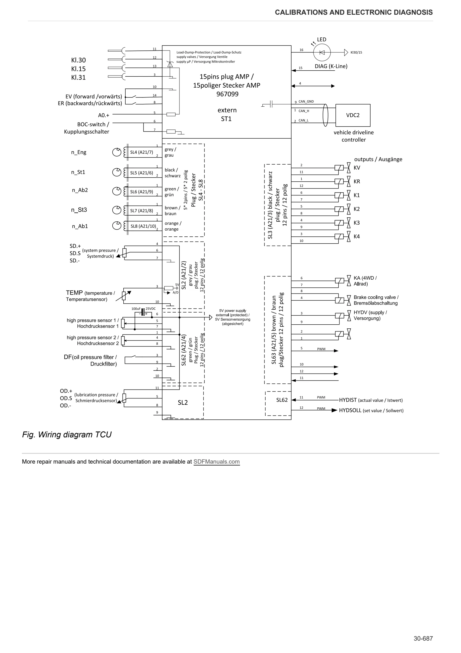
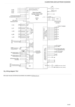
- TCU pin assignment
Armrest alarms
- PLA_2 Armrest Alarms List
HLHP alarms
- HLHP2 alarm list
AC system alarms
- Manual Air Conditioner Alarms
- Automatic Climate control unit alarms list
EPB Alarms
- EPB alarms list
Electronic battery master switch alarms
- Alarm List, Electronic Battery Master Switch
Electrohydraulic control valve alarms
- Distributor alarms
Software management
- Universal firmware update for ECUs installed on pre-T4F SDF vehicles
- iMonitor 8” – Software update
Method of intervention
- Index Repair instructions
B0 – Engine
- A/C drive belt alignment and tension adjustment
- Removal and refitting of the crankcase breather
- Removal and refitting of the crankcase breather
- Renewal of the crankshaft oil seal
- Changing the crankshaft ring gasket (flywheel side)
- Installation and removal of the crankshaft sleeve
- Removal and refitting of the front cover (fixing elements)
- Removal and refitting of the oil sump pan
- Removal and refitting of the oil filler pipe
- Removal and refitting of the V-belt pulley
- Removal and refitting of the torsional vibration damper
- Removal and refitting of the flywheel (fixing elements)
- Compression test
- Removal and refitting of the cylinder head cover
- Check and adjust valve clearances
- Removal and refitting of oil cooler (auxiliary services)
- Removal and refitting of the lube oil cooler housing
- Removal and refitting of the pilot block
- Removal and refitting of the high-pressure pump, Installation position A
- Installation and removal of the high pressure pump, Assembly position B
- Removal and refitting the injectors
- Removal and refitting of the common rail
- Removal and refitting of the charge air duct
- Removal and refitting of the charge air manifold
- Removal and refitting of the air intake pipe
- Removal and refitting of the water pump
- Removing and installing the belt tensioner (Level 1).
- Removing and installing the support plate (Level 1)
- Removing and installing the support console (Level 1)
- Removal and installation of the exhaust pipe (auxiliaries)
- Removal and refitting of the exhaust gas turbocharger
- Removing and refitting the lubricating oil pipe (exhaust gas turbocharger)
- Removal and refitting of the lubricating oil return pipe (exhaust gas turbocharger)
- Removing and installing the belt tensioner (Level 2)
- Removing and installing the vee-groove pulley (#1)
- Removing and installing the vee-groove pulley (#2)
- Removing and installing the support console (Level 2)
- Removing and installing the console (Level 1)
- Removing and installing the support console (Level 2)
- Replacing the tensioner pulley
- Assembly and disassembly of the piston cooling nozzles (L3)
- Assembly and disassembly of the piston cooling nozzles (L3)
- Replacing the starter ring gear on the flywheel (L3)
- Replacing the starter ring gear on the flywheel (L3)
- Fitting and removing counterweight drive system, checking (L3)
- Assembly and disassembly of the crankshaft (L3)
- Crankshaft check (L3)
- Check the endfloat of the crankshaft (L3)
- Fitting and removing crankshaft bearings (L3)
- Check the crankshaft bearings (L3)
- Assembly and disassembly of the connecting rod drum (L3)
- Connecting rod drum check (L3)
- Replace the crankshaft O-ring (flywheel end) (L3)
- Disassembly and assembly of the gear box (L3)
- Disassembly and assembly of the gear box (L3)
- Disassembly and assembly of the gear box (L3)
- Assembly and disassembly of the camshaft (L3)
- Check the camshaft (L3)
- Assembly and disassembly of the distribution valve (L3)
- Removing and refitting the valve timing system (L3)
- Assembly and disassembly of the control elements (L3)
- Assembly and disassembly of the oil intake pipe (L3)
- Assembly and disassembly of the oil intake pipe (L3)
- Disassembly and completion of the pilot unit (L3)
- Disassembly and completion of the pilot unit (L3)
C0 – Engine accessories
- Removal and installation of the fuel filter console
- Removal and installation of the fuel lift pump
- Removal and refitting of fuel lines (fuel lift pump – pilot block)
- Removal and refitting of fuel lines (pilot block – high pressure pump)
- Removal and refitting of fuel lines (pilot block – fuel lift pump)
- Removal and refitting of fuel lines (rail, cylinder head, pilot block – fuel filter)
- Removal and refitting of the heater
- Removal and refitting of the heater (details)
- Installing and removing the thermostat
- Thermostat check (with thermostat disassembled)
- Removal and installation of the thermostat housing
- Removal and refitting of the fan support
- Removal and assembly of the fan support
- Installing and removing the temperature transmitter (Exhaust gas)
- Removal and refitting of the starter motor
- Removal and refitting of the alternator (ribbed V-belt, level 2)
- Removal and refitting of the alternator (ribbed V-belt, level 1)
- Removal and refitting of the crankshaft speed sensor
- Removal and refitting of the camshaft speed sensor
- Installation and removal of the rotation device
- Installation and removal of the rotation device (torsional vibration damper)
- Removal and installation of the air conditioning compressor
- Replacing the exhaust gas temperature sensor
- Diesel fuel tank
- AdBlue pump filter
D0 – Transmission
- Separation of Rear Axle from Transmission
- Removal of cartridge
- Disassembly of shifting drum
- Disassembly of P1 ring gear carrier
- Disassembly of P1/P2 Planetary drive
- Disassembly of P5/P6 Planetary drive
- Disassembly of KV clutch
- Disassembly of K1 clutch
- Disassembly of K3/K4 clutch and P3/P4 planetary drive
- Disassembly of K3/K4 clutch
- Disassembly of P3/P4 planetary drive
- Disassembly of KR clutch
- Disassembly of K2 Clutch
- Disassembly of Hydrostatic Unit
- Disassembly of control (TCU)
- Disassembly of pump
- Disassembly of suction filter
- Disassembly of Valve Block
- Disassembly of Valve Block
- Disassembly of Valve Block (P.R.V. – Pressure Relief Valve)
- Disassembly of W.H. and E.C.U.
- Disassembly of inductive sensors
- Disassembly of plug-in module
- Disassembly of output shaft
- Disassembly of intermediate housing
- Disassembly of drive shaft
- Reassembly of Transmission Housing
- Reassembly of drive shaft
- Reassembly of intermediate housing
- Reassembly of Plug-In Module
- Reassembly of output shaft
- Preassembly of Housing Lid
- Reassembly of Inductive Sensors
- Reassembly of W.H. and E.C.U.
- Reassembly of Valve Block (P.R.V. – Pressure Relief Valve)
- Reassembly of Valve Block
- Reassembly of Valve Block
- Reassembly of pump
- Reassembly of Control
- Reassembly of Hydrostatic Unit
- Reassembly of suction filter
- Reassembly of K2 Clutch
- Reassembly of KR clutch
- Reassembly of P3/P4 planetary drive
- Reassembly of K3/K4 Clutch
- Reassembly of K1 Clutch
- Reassembly of KV Clutch
- Reassembly of P5/P6 planetary drive
- Reassembly of P1/P2 planetary drive
- Reassembly of P1 Ring gear carrier
- Reinstallation of cartridge
- Fitting of rear axle to the transmission
- Pipes and closing components
E0 – Rear axle
- Removing the axle housing
- Removing brakes
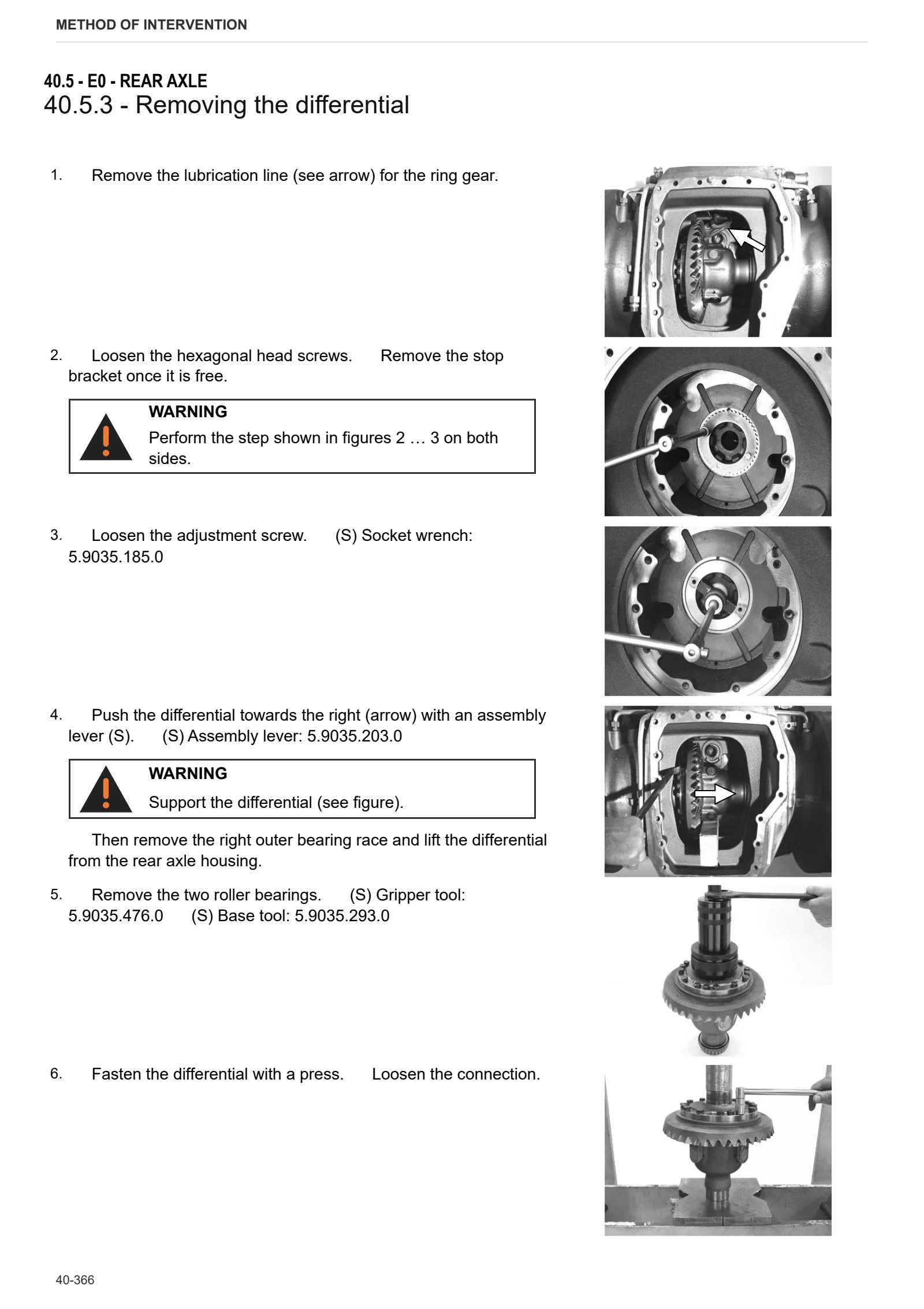
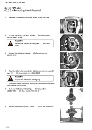
- Removing the differential
- Removing the PTO
- Removing the oil feed
- Removing the lifter
- Fitting lifter, oil feed and blanking elements
- Fitting the lifter
- Fitting the oil feed
- Fitting blanking elements
- Fitting the PTO
- Fitting the differential
- Fitting brakes
- Fitting the axle housing
- Procedure to check EPB stroke
F0 – Front axle
- Toe-in/steering angle/assembly tests
- Steering cylinders assembly
- Axle shaft assembly
- Flange assembly
- Differential assembly – carrier
- Checking the bevel gear pair
- Differential disassembly
- Axle pivot bearings assembly
- Bevel pinion assembly
- Planetary reduction gear assembly
- Wheel hub assembly
- Brake assembly
G0 – Bodywork – Cab – Platform
- Air conditioning system diagnosis
H0 – Hydraulic system
- Purge air from hydraulic brake system
- Air tanks
L0 – Electrical system
- Fitting BDS cables
- Steering position sensor assembly
V0 – Ballast – towing hitches
- Tightening Torques for Tow Hitches
- Standard fastener hardware: Tightening torque/Tension forces
V1 – AFTERMARKET KITS
- Installing air conditioning kit in S2 cabs
- Accumulator kit installation (P/N 9.AD366.90.0)
- Brake kit installation (P/N 9.AD375.90.0)
Wiring diagrams
Introduction
- Introduction
- Basic electronics for mechanics (1/2)
- Basic electronics for mechanics (2/2)
- Electrical and electronic components (1/2)
- Electrical and electronic components (2/2)
Components
- 2.8519.133.0 – Transmission control unit
- 2.8519.134.0 – HLHP control unit
- Engine control unit
- Main power relay switch (TGC/RME-SA1)
- A – Starting and charging
- B – Fuses
- C – Earths
- D – Intermediate connections
- E – On-board instruments and visual and audible indicators
- F – External lights
- G – Interior lights
- H – Electrical and manual controls
- I – Circuit breakers
- J – Relays
- K – Sensors and transmitters
- L – Electromagnets and solenoid valves
- M – Electrical/electronic devices, flasher units and timers
- N – Electric motors and actuators
- O – Resistors and rheostats
- P – Various services
- R – Diagnostics
- T – Power supply points
Systems
- S001 – Electrical engine governor
- S002 – Starter
- S003 – Preheating
- S004 – AdBlue
- S005 – Transmission
- S006 – Front axle suspension
- S007 – Instrument panel
- S008 – Lights – Version without front lift
- S009 – Lights – Version with front lift
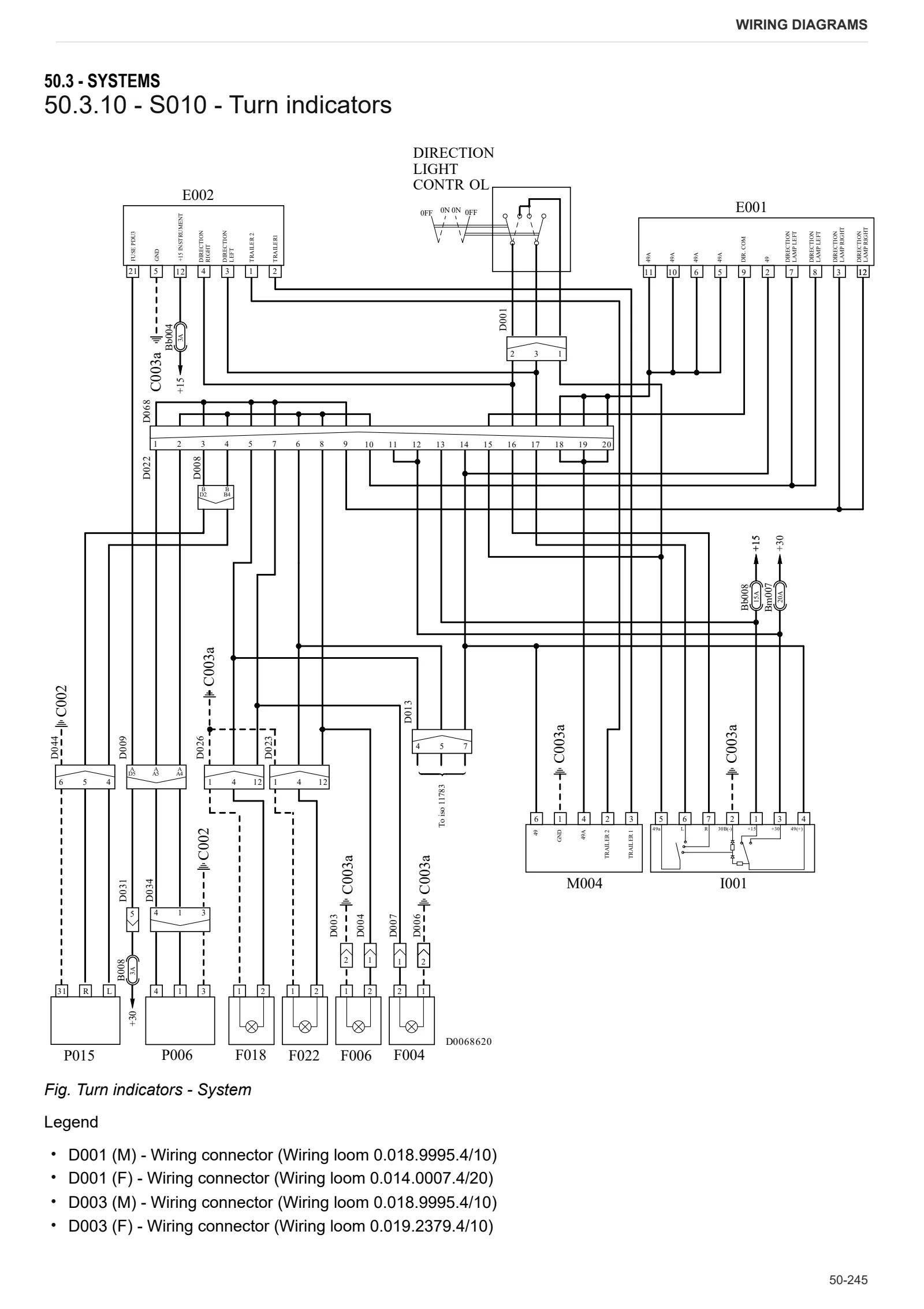
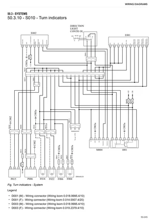
- S010 – Turn indicators
- S011 – Work lights
- S012 – Semi-active cab suspension
- S013 – Air Conditioning
- S013A – Automatic A/C system
- S014 – +15 Positives
- S015 – +30 Positives
- S016 – CAN BUS Line – Standard version
- S016A – CAN BUS line – Version with automatic A/C system
- S017 – CAN BUS Line – Version with ISO 11783
- S018 – CAN BUS line – Version without I-Monitor
- S019 – PTO
- S020 – Front and rear lifts
- S021 – Brakes
- S022 – Hydraulic trailer braking
- S023 – Hydraulic distributors
- S024 – Windscreen wipers
- S025 – Radio
- S026 – Accessories
- S027 – Diagnostics
- S028 – Monitor
- S029 – ISO 11783
- S030 – Lights – Version without front lift (U.S.A.)
- S031 – Lights – Version with front lift (U.S.A.)
- S032 – Turn indicators (U.S.A.)
- S033 – Work lights (U.S.A.)
- S034 – +15 Positive (U.S.A.)
- S035 – +30 Positives (U.S.A.)
- S036 – PTO (USA)
- S037 – Brakes (U.S.A.)
- S038 – ISO 11783 (U.S.A.)
Wiring harnesses
- 0.012.2018.4/20 – License plate light
- 0.014.0007.4/20 – Lights selector switch
- 0.014.5144.4/10 – Battery negative
- 0.015.3974.4/10 – Front axle suspension
- 0.015.4257.4/10 – PTO sensor (USA)
- 0.015.5429.4/20 – Front lift control
- 0.016.0642.4/20 – Rear LH lower work light on cab – Xenon version
- 0.016.0642.4/20 – Rear RH lower work light on cab – Xenon version
- 0.016.0650.4/10 – LH front supplementary work light on arm – Xenon version
- 0.016.0650.4/10 – RH front supplementary work light on arm – Xenon version
- 0.017.0496.4/10 – Supplementary LH front work light on arm
- 0.017.0496.4/10 – Supplementary RH front work light on arm
- 0.017.0497.4/20 – Rear RH lower work light on cab
- 0.017.0497.4/20 – Rear LH lower work light on cab
- 0.017.0789.4/10 – LH mudguard (U.S.A.)
- 0.017.0789.4/10 – RH mudguard (U.S.A.)
- 0.017.8425.4 – Rear trailer socket
- 0.017.8426.4 – Rear trailer socket (U.S.A.)
- 0.017.8887.4/10 – ISO 11783 – Front line
- 0.018.8803.4/10 – Battery positive terminal
- 0.018.9843.4/10 – ISO 11783 – Rear line
- 0.018.9845.4 – Fuses and relays
- 0.018.9985.4/10 – LH transmission
- 0.018.9986.4/10 – RH transmission
- 0.018.9990.4/10 – Distributors
- 0.018.9992.4/10 – AdBlue
- 0.018.9995.4/10 – Side console
- 0.019.0059.4/10 – Roof
- 0.019.2378.4/10 – RH mudguard
- 0.019.2378.4/10 – LH mudguard
- 0.019.2379.4/10 – Front RH lower work lights on cab
- 0.019.2379.4/10 – Front LH lower work lights on cab
- 0.019.2380.4/10 – Hazard warning lights switch (USA)
- 0.019.2383.4/20 – Engine cowl
- 0.019.2474.4/10 – Rear PTO
- 0.019.2539.4/10 – Hydraulic braking
- 0.019.2571.4/10 – ISO 11786
- 0.019.2617.4/30 – ISO 11783 – Cab line
- 0.019.2618.4/20 – On-board monitor
- 0.019.3658.4/10 – AGROSKY solenoid valves
- 0.019.3657.4/10 – LH rear work lights on cab roof – Version with Agrosky
- 0.019.3659.4/10 – On-board monitor – Armrest
- 0.019.4559.4/10 – Rear service work light
- 0.019.4688.4/10 – Front top work lights on cab
- 0.019.4689.4/20 – RH rear work lights on cab roof
- 0.019.4689.4/20 – LH rear work lights on cab roof
- 0.019.4711.4/10 – Semi-active cab
- 0.019.4913.4/10 – Front top work lights on cab – LED version
- 0.019.4914.4/20 – RH rear work lights on cab roof – LED version
- 0.019.4914.4/20 – LH rear work lights on cab roof – LED version
- 0.019.5311.4/10 – Automatic A/C system interface
- 0.019.6969.4/10 – LH rear work lights on cab roof – LED version with Agrosky
- 0.900.0816.0 – Front PTO
- 04436707 – Left hand rotating beacon
- 04436707 – RH rotating beacon
- 04217216 – Preheating relay power supply
- 04217217 – Preheating
- 04217865 – Engine
- 0.019.4848.4/10 – Manual A/C system
- 0.019.5518.4/10 – Automatic A/C system
Service Info
A0 – TRACTOR
- Diagnostics 2026 subscription
- After-sales 2026 subscription
- SERVICE NEWS RESEARCH GUIDE
- Diagnostics 2025 subscription
- After-sales 2025 subscription
- Diagnostics 2023 subscription
- Diagnostics 2024 subscription
- Diagnostics 2022 subscription
- Diagnostics 2021 subscription
- Importance of 1st service at 50 operating hours
- After-sales 2024 subscription
- After-sales 2023 subscription
- After-sales 2022 subscription
- After-sales 2021 subscription
- After-sales 2019 subscription
- SDF Parts and SDF Service DVV 04/2014, version 26
- New function: Download PDF manuals
- Diagnostics – 2020 subscription
- After-sales – 2020 subscription
- After-sales – 2018 subscription
- Service and Spare Parts – 2017 Subscription
- SDF Parts and SDF Service DVDs 05/2014 version 25
- SDF Parts and SDF Service DVDs 03/2013 version 24
- DiagnosiS EMR 4 – Serdia 2010
B0 – ENGINE
- Flushing the lubrication circuit
- Deutz AG engine oil specifications
- SerDia 2010 updating license file
C0 – ENGINE ACCESSORIES
- Diagnostic protocol – AdBlue – Float level unit
- AdBlue feed pump cleaning
- AdBlue system trouble shooting
- AdBlue crystallization
- Solid urea deposits in catalytic converter
- NOx sensor (Generation 2.0/2.5)
- Filter and prefilter tool p/n 5.9035.865.0
F0 – FRONT AXLE
- Check the front axle steering knuckles for wear
- Steering behavior check procedure
G0 – BODYWORK – CAB
- Trouble shooting protocol for EPB failures
- Air conditioning with error U90
- Air conditioning system recharging
- COMMON Trouble shooting protocol for EPB failures
H0 – HYDRAULIC AND PNEUMATIC SYSTEM|
- Hydraulic CUNA trailer braking kit (ITALY)
- Single connection hydraulic braking kit availability update – only for EUROPEAN market
- L0 – ELECTRIC AL SYSTEM