Document overview
Workshop Manual for DEUTZ FAHR 4100 EF → NNZRJ70200BD00001 from the Series 4EF (FARMOTION STAGE 5) family. Digital PDF in English with 610 pages.
The corresponding English table of contents contains 39 sections and 257 individual topics.
Main sections included
- Introduction
- Safety
- Technical characteristics
- Calibrations and electronic diagnosis
- Method of intervention
- Wiring diagrams
- Service Info
Document details
- Brand: DEUTZ FAHR
- Family: Series 4EF (FARMOTION STAGE 5)
- Model: 4100 EF
- Starting serial number: NNZRJ70200BD00001
- Document type: Workshop Manual
- Language: English
- Pages: 610
- File size: 187.60 MiB
- Format: Digital PDF download
Compatibility
Before purchasing, verify that your machine model and reference code match DEUTZ FAHR 4100 EF → NNZRJ70200BD00001.
Complete table of contents
Introduction
- Tightening torques
- Wheel nut/screw tightening torques
- Tightening torques for nuts and bolts of electrical connections
- Installation of solenoid valves and cartridge valves
- Installation of quick couplers
- One-way valves
- Fixing the steering wheel
Safety
- Safety
Preface
- Important notes concerning safety
Important safety information
- Recognising hazards
- Indications for persons in contact with the tractor
Safety rules
- Risks during tractor preparation
- Risks during maintenance
- Work on machine systems
- Special disassembly/assembly/inspection procedures
Safety pictograms
- Replacing safety pictograms
Environmental risks
- Hazards associated with the operating environment
Technical characteristics
Engine
- Introduction – Engines
- Cold start system (preheat glow plugs)
- Engine cooling system
- Engine intake system
- Engine injection system – low pressure circuit
- Exhaust backpressure, engine oil temperature
- Fuel injection system – Common Rail System
- Engine air intake system
- Turbocharging system
- Exhaust gas recirculation system (EGR)
- Exhaust aftertreatment system
- Technical data and exhaust gas after-treatment systems – KF stage 5 engine
- Technical data, rockers – tappets
- Technical data and dimensions: valves – valve springs
- Technical data and dimensions: heads – valve guides – valve seats
- Technical data: counter-rotating masses
- Technical data: timing system gears
- Camshaft technical data
- Technical data: Connecting rods
- Technical data: pistons – piston rings
- Technical data: crankshaft
- Technical data: cylinder block
Transmission
- Transmission
- Clutch housing
- Range gearbox and parking brake assembly
- Four-wheel drive engagement assembly
- Rear PTO
- Hydraulic reverse power shuttle
Rear axle
- Brakes and rear axle assembly
- Rear differential assembly
Front axle
- Front axle
- Pinion and Differential
- Final drive
Hydraulic system
- Hydraulic lift control valve
- Trailer braking valve
- LH 8 cc hydraulic pump
- RH 19 cc hydraulic pump
- Hydrostatic steering
- 4-way remote control valve
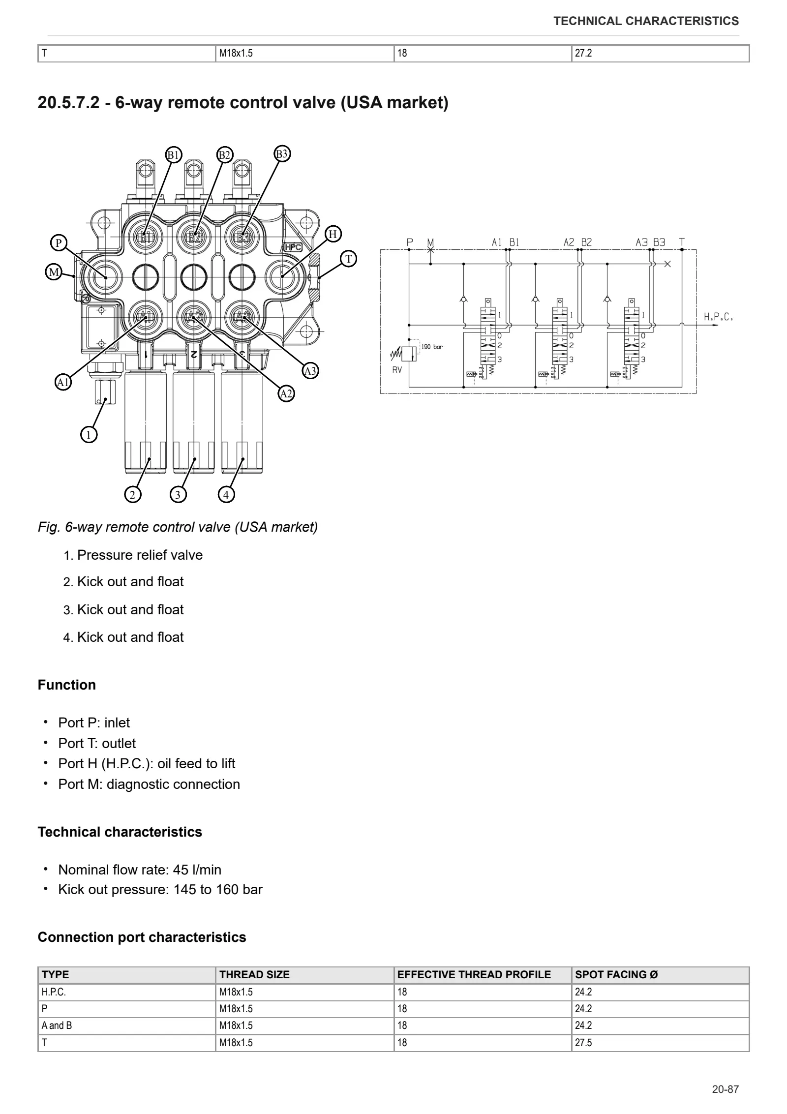
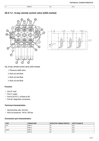
- 6-way auxiliary control valve
- Base hydraulic circuit
- Optional hydraulic circuit 2
Rear lift
- Rear lift
Calibrations and electronic diagnosis
Diagnostic tools
- D-TECH App
ECU alarms
- SDF Severity of alarms
- ECU ALARMS
Software management
- ECUs firmware update
- Download Dataset FARMotion & Flash ECU
- ECUs
- On-board instruments (Cluster/Display) flashing
Method of intervention
B0 – Engine
- Tightening procedure for engine components
- Adjusting oil pump gear backlash
- Aligning water pump and crankshaft pulleys
- Power take off gear backlash adjustment
- Test of the thermostat valve
- Engine block-gearbox connector flange
- Cooling jets
- Engine flywheel
- Belt tensioner mounting plate.
- Automatic belt tensioner
- Air compressor belt
- Ancillary utility belt
- Crankshaft pulley and tone wheel
- Crankshaft pulley complete with tone wheel
- Crankshaft
- Disassembling pistons and connecting rods
- Cylinder sleeves
- Power take off drive
- Front timing cover
- Rear flange
- Cylinder head covers
- Pushrods
- Cylinder heads
- Intermediate gear and timing
- Disassembling the cylinder heads
- Engine oil and filter
- Turbocharger oil pipes
- Blow-by filter
- Blow-by oil vapour pipe
- Oil sump
- Oil pump
- Oil vapour pipe
- Electro-injectors and common rail
- Thermostat valve
- Coolant manifold
- Oil heat exchanger
- Engine coolant pump
- EGR exhaust gas recirculation pipe
- EGR exhaust gas cooling pipe
- EGR manifold
- Disassembly of the EGR manifold
- Exhaust gas pressure line
- Exhaust manifold
- Intake manifold
- Turbocharger
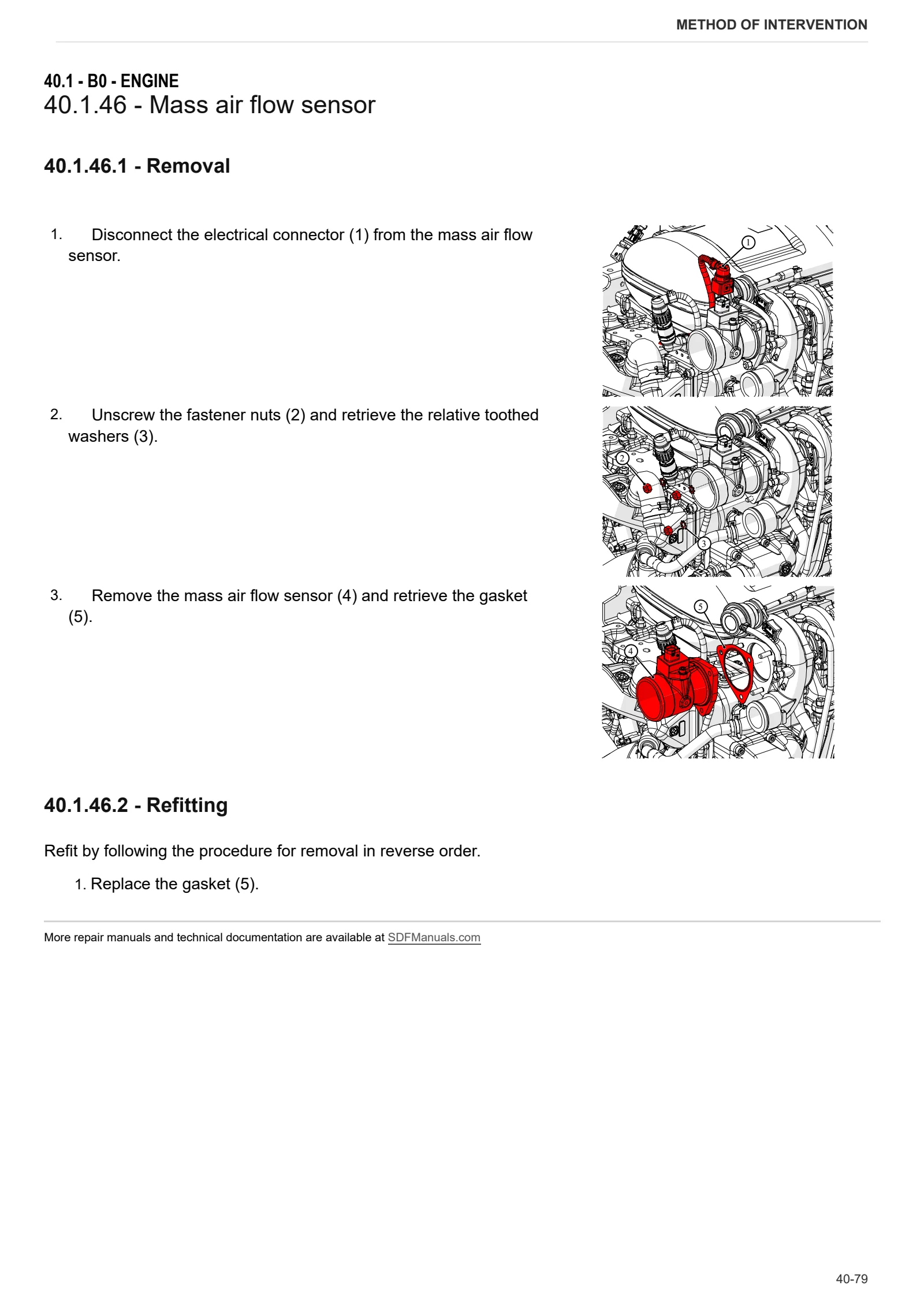
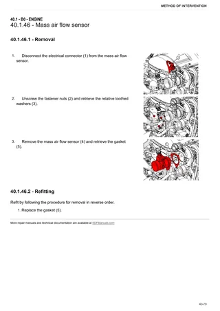
- Mass air flow sensor
- EGR valve
- AdBlue injector
- NOx sensor
- DOC outlet side exhaust temperature sensor
- DOC inlet side exhaust temperature sensor
- Exhaust gas pressure sensor
- Throttle valve actuator
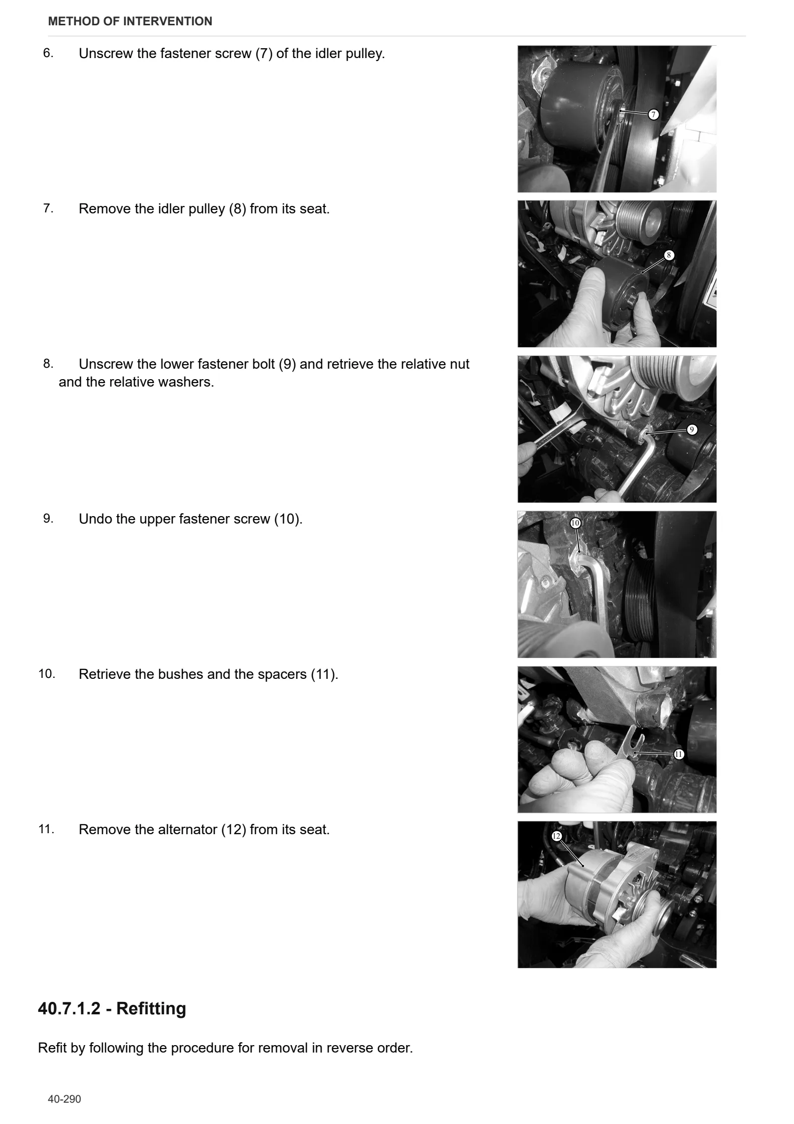
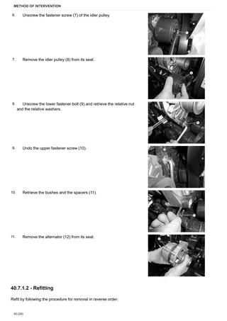
- Alternator
- Boost pressure sensor and air temperature sensor
- Mass air flow sensor
- Crankshaft speed sensor
- Camshaft timing sensor
- Engine oil pressure switch
- Coolant temperature sensor
- Engine oil temperature sensor
- Fuel pressure sensor
- Water in fuel sensor
C0 – Engine accessories
- Alternator mount
- Transverse plate
- Mounting brackets
- Fuel pump
- Fuel prefilter
- Fuel filter
- Filter mounting plate
- High pressure fuel pump
- Glow plug
- Preheat relay
- Starter motor
- Exhaust pipe
- DOC outlet side exhaust flange
- DOC inlet side exhaust flange
- DOC exhaust silencer
- Air compressor
- Replacing the coolant
- Bleeding the fuel circuit
- Diesel fuel tank
D0 – Transmission
- Draining and filling the transmission oil
- Separating front gearbox housing from rear gearbox housing
- Clutch plate wear check
- Clutch plates
- Thrust plate assembly
- Assembly of the HI-LO unit in the front gearbox housing
- Internal PTO drive shaft
- Disassembling the gearbox input shaft
- Disassembly of the main shaft
- Disassembling the secondary shaft
- Adjusting endfloat of the secondary shaft gears
- Complete gearbox assembly
- Range selector rod cover
- Disassembling the gear selector rod
- Pinion
- Range reduction gearbox shaft
- Bevel gear adjustments
- PTO input shaft
- PTO input shaft disassembly
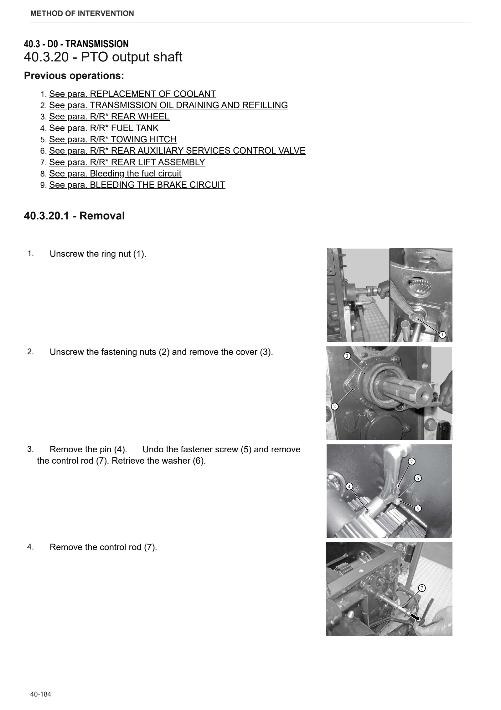
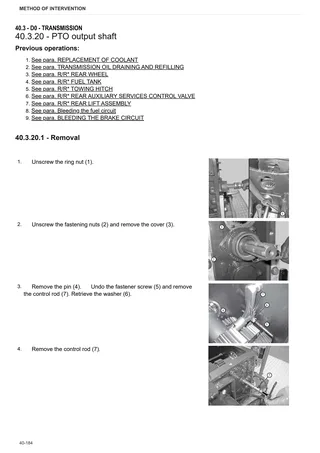
- PTO output shaft
- Assembly of PTO output shaft ring nut
- Ground speed PTO shaft
- Parking brake disc sectors
- Disassembling the parking brake lever
- 4WD engagement device
- 4WD output shaft in transmission.
- Disassembly of dual traction output shaft
- Parking brake unit assembly
E0 – Rear axle
- Bleeding air from the hydraulic brake system
- Rear axle
- Left-hand rear axle
- Disassembling rear axle
- Planet gear carrier
- Disassembling the planetary gear unit
- Rear brake discs
- Brake housing
- Rear differential lock control fork
- Rear differential
- Removing the rear differential
F0 – Front axle
- 4WD shaft
- Carrier with front axle
- Front axle
- Adjusting front axle endfloat
- Steering cylinders
- Disassembling the steering cylinder
- Pinion-differential assembly
- Differential lock
- Differential lock device adjustment
- Disassembling the bevel gear set
- Disassembling the front axle differential – Complete assembly
- Adjustment of the differential preload
- Adjusting pinion position
- Adjusting pinion/crown wheel backlash
- Adjusting pinion bearing preload
- Planetary reduction gearbox
- Disassembly of the planetary reduction gearbox
- Complete steering knuckle housing
- Adjusting bearing preload
- Front brake discs
- Front axle brake piston
H0 – Hydraulic system
- Ancillary pump
- Power steering pump
- Hydrostatic steering (orbitrol)
- Rear ancillary distributor
- Disassembling the rear ancillary utility distributor
L0 – Electrical system
- Alternator
- Engine control unit
- FARMotion engine sensors
- Sensors and components of the FARMotion engine exhaust system
- FARMotion engine components
- Engine wiring loom
- Electro-injector wiring loom
- Preheat glow plug wiring loom
R0 – Rear lift
- 3-point linkage
- Rear lift
- Distributor for mechanical SAC
- Rear lift – Complete assembly
- Disassembling the lift cylinder
- Replacing bushes
- Hitch control distributor
- Disassembling the lift control distributor
- Adjusting the SAC, low range 50 HP version
- Mechanical draft sensor
- Mechanical draft sensor disassembly
S0 – Wheels
- Front Wheels
- Rear wheels
V0 – Ballast – towing hitches
- Front ballasts and support
- Rear wheel ballasts
- Rear tow hitch
Wiring diagrams
- Wiring looms
- W-TECH – ELECTRICAL SECTION
Service Info
A0 – TRACTOR
- Diagnostics 2026 subscription
- After-sales 2026 subscription
- SERVICE NEWS RESEARCH GUIDE
- Diagnostics 2025 subscription
- After-sales 2025 subscription
B0 – ENGINE
- FARMotion seal ring leakage
- Belt Tensioner FarMotion Engine
C0 – ENGINE ACCESSORIES
- Diagnostic protocol – AdBlue – Float level unit
F0 – FRONT AXLE
- Bevel gear set loosing screws
G0 – BODYWORK – CAB
- SERVICE NEWS – Brake Fluid Reservoir vent missing
- Oil leakage from easy-lift cylinder 0.036.2115.4
H0 – HYDRAULIC AND PNEUMATIC SYSTEM|
- Hydraulic CUNA trailer braking kit (ITALY)
- Single connection hydraulic braking kit availability update – only for EUROPEAN market
L0 – ELECTRIC AL SYSTEM
- SERVICE NEWS – M334-M335-M430-M28-M427 New Engine SW release A09 (FarMotion Stage 5)
- PTO switch not working
V1 – AFTERMARKET KITS
- Check correct installation of braking KIT
- Instructions for kit aftersales