

Document overview
Workshop Manual for DEUTZ FAHR AGROTRON 6170 TTV → WSXKP10200LD10001 from the Series 6 Agrotron TTV (STAGE 3A – STAGE 4) family. Digital PDF in English with 1,242 pages.
The corresponding English table of contents contains 43 sections and 494 individual topics.
Main sections included
- Introduction
- Safety
- Technical characteristics
- Calibrations and electronic diagnosis
- Method of intervention
- Wiring diagrams
- Service Info
Document details
- Brand: DEUTZ FAHR
- Family: Series 6 Agrotron TTV (STAGE 3A – STAGE 4)
- Model: AGROTRON 6170 TTV
- Starting serial number: WSXKP10200LD10001
- Document type: Workshop Manual
- Language: English
- Pages: 1,242
- File size: 586.63 MiB
- Format: Digital PDF download
Compatibility
Before purchasing, verify that your machine model and reference code match DEUTZ FAHR AGROTRON 6170 TTV → WSXKP10200LD10001.
Complete table of contents
Introduction
- Tightening Torques
- Wheel rim to hub screws and nuts tightening torques
- Tightening torques for nuts and bolts of electrical connections
- Installation of solenoid valves and cartridge valves
- Installation of quick couplers
- One-way valves
- Spool valves
Safety
Preface
- Important notes concerning safety
Important safety information
- Recognising hazards
- Indications for persons in contact with the tractor
Safety rules
- Risks during tractor preparation
- Risks during maintenance
- Work on machine systems
- Special disassembly/assembly/inspection procedures
Safety pictograms
- Replacing safety pictograms
Environmental risks
- Hazards associated with the operating environment
Technical characteristics
- External views
- Viste interni cabina
- Dimensions and weights of the tractor
- Main technical data
Engine
- Motor description – construction type
- Engine description – Images of engine
- Engine description – Lubricant oil diagram
- Engine description – Fuel circuit diagram
- Engine description – Coolant diagram
- Engine description – Exhaust gas recovery
- Engine description – Exhaust gas after-treatment
- Engine description – Electrical/electronic system
- Technical data – Engine data and adjustment data
- Faults – Engine management
Engine accessories
- Technical data – Pressure transducer
- Technical data – Pressure sensor
- Technical data – Pressure/temperature transmitter
- Technical data – Temperature transmitter
- Technical data – Temperature transmitter
- Technical data – Temperature sender
- Technical data – Speed indicator
- Technical data – Speed indicator
- Technical data – Level transducer/temperature sender
Transmission
- Gearshift pattern
- Hydrostatic unit
- Shifting drum
- Layout of rear axle
- Assisted parking brake APB
- PTO shaft
- Control block for system pressure
- Control block for clutches
- Hydraulic diagram
- Data sheet
- Oil Quantity
- Oil sump temperatures
- Diagnostic levels of the transmission control unit
- Definition of system reaction of the transmission control unit
- Setting the assisted parking brake for initial operation
Bodywork – Cab – Platform
- Roof panel
- Provision for radio
- Air conditioning system
- Air conditioning system compressor
- Air conditioning condenser
- Ballasts – Technical data
- Ballasts
- Drawbar
Front PTO
- Front PTO
Front lift
- Front lift
Rear lift
- Rear lift
- Rear 3-point linkage
Calibrations and electronic diagnosis
Diagnostic tools
- D-Tech and diagnostic ports
- D-TECH App
ECU alarms
- SDF Severity of alarms
- ECU ALARMS
Method of intervention
- Tools for engine disassembly and reassembly
- Workshop tools for engine disassembly and reassembly (Lv.2)
B0 – Engine
- Checking crankcase pressure
- Disassembling and assembling crankcase breather
- Pipe (crankcase breather)
- Replace the crankshaft O-ring (flywheel end)
- Replacing the crankshaft O-ring (opposite end to flywheel)
- Disassembling/assembling crankshaft wear sleeve (side opposite flywheel)
- Disassembling and assembling the front cover (fixing elements)
- Blanking elements
- Blanking tool (crankcase)
- Blanking elements
- Blanking elements
- Blanking tools (crankcase, electronic engine governor)
- Blanking elements (crankcase, PTO-A)
- Blanking elements (crankcase, PTO-A)
- Blanking elements (PTO-B)
- Blanking elements (PTO-B)
- Oil dipstick
- Oil filler neck
- Oil filler neck
- Disassembling and assembling the lubricant oil sump (pressed steel sump)
- Removing and fitting lubricant oil sump (heavy version)
- Removing and fitting lubricant oil sump (heavy version)
- Removing and fitting lubricant oil sump (heavy version)
- Removing and fitting lubricant oil sump (heavy version)
- Disassembling and assembling the oil suction pipe
- Removing and fitting the V belt pulley/poly-V belt pulley
- Disassembling and assembling the torsional vibration damper
- Disassembling and assembling the torsional vibration damper
- Disassembling and assembling the flywheel (fixing elements)
- Replacing the starter motor ring gear on the flywheel
- Compression test
- Removing and fitting the cylinder head cover
- Disassembling and assembling the cylinder head (fasteners)
- Measuring piston protrusion
- Assembly and disassembly of the valves
- Checking valves, valve guides, valve springs and valve recess
- Blanking elements (cylinder head)
- Blanking elements
- Eye-bolt for transporting (cylinder head)
- Removing and fitting the lubricant oil radiator housing
- Disassembling and assembling the oil cooler
- Disassembling and assembling the lubricant oil radiator (blanking elements)
- Removal and refitting of oil cooler (auxiliary services)
- Disassembling and assembling the lube oil cooler housing
- Removing and refitting lubricant oil cooler housing (fastener elements)
- Heater connector (Lubricant oil cooler housing)
- Removing and fitting the reservoir
- Blanking elements (lubricant oil cooler housing)
- Blanking elements (lubricant oil cooler housing)
- Disassembly and assembly of the fuel control unit (fastening elements)
- Disassembly and assembly of the fuel control unit (fastening elements)
- Disassembly and completion of the fuel control unit
- Disassembling and assembling the high pressure pump (fastener elements)
- Disassembling and assembling the injector (1600 bar injection system)
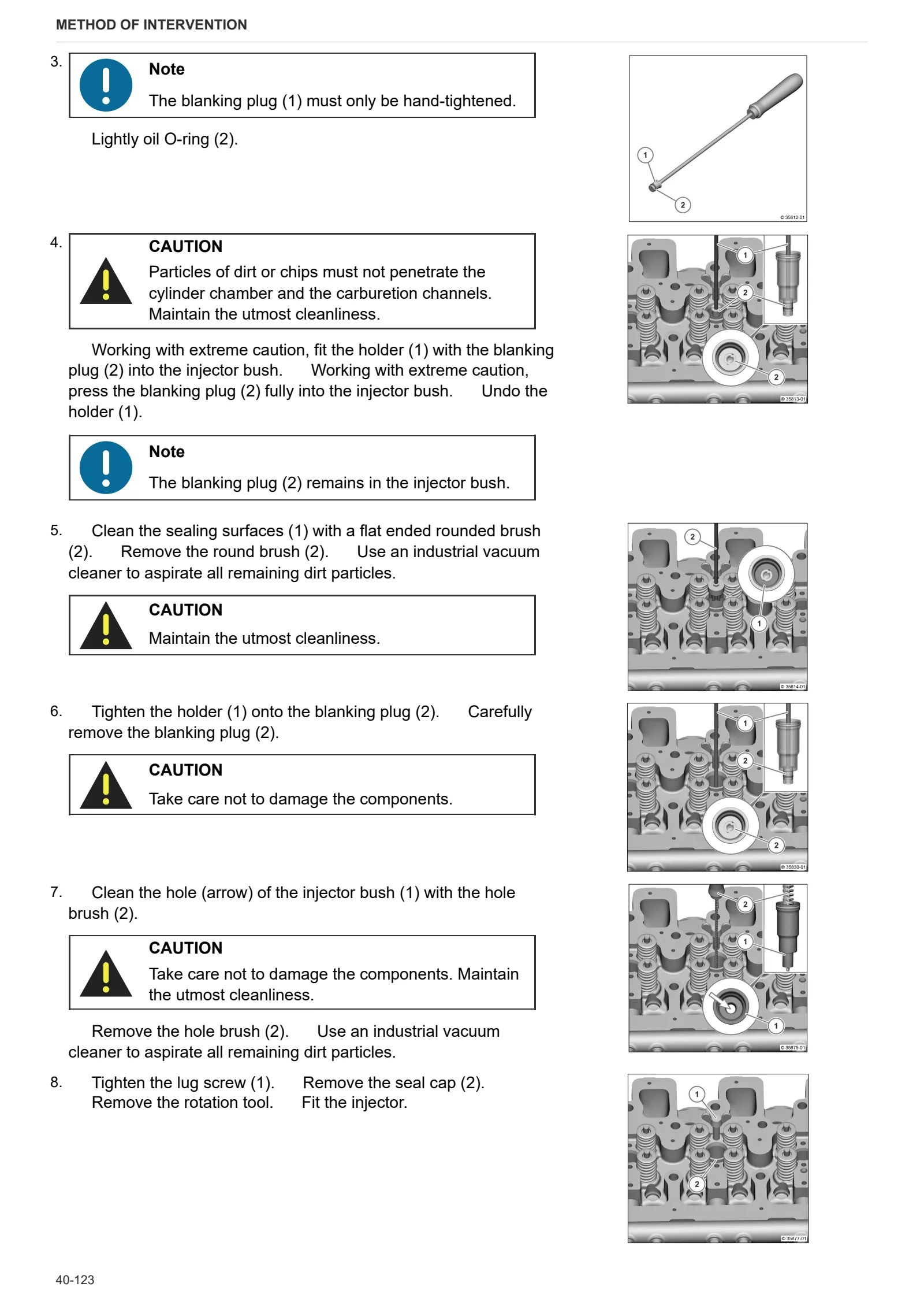
- Replacing the injector bush
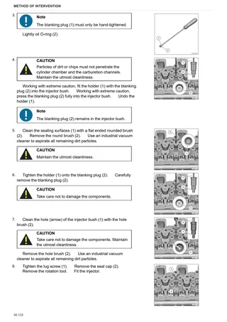
- Clean the injector bush
- Clean the injector bush seat
- Disassembling and assembling the rail (1600 bar injection system)
- Disassembling and assembling the rail (1600 bar injection system)
- Removing and fitting the pressure cut-off valve (rail)
- Removing and fitting the rail pressure sensor
- Removing and fitting the coolant pump
- Transmission components (coolant pump)
- Assembling and disassembling the thermostat
- Disassembling and assembling the thermostat
- Check the thermostat (after removing)
- Check the thermostat (after removing)
- Removal and installation of the thermostat housing
- Removal and installation of the thermostat housing
- Check the seal of the cooling system
- Blanking elements (coolant pump – thermostat housing)
- Blanking elements (thermostat housing)
- Blanking elements (thermostat housing)
- Blanking elements (thermostat housing)
- Blanking elements (thermostat housing)
- Blanking screws (thermostat housing)
- Hose connector (thermostat housing)
- Connection (Compensation tank)
- Disassembly and refitting of the belt tensioner (ribbed V-belt, level 1)
- Removing and fitting the mounting plate (ribbed V-belt, level 1)
- Removing and installing the support console (Level 1)
- Removing and installing the belt tensioner (Level 2)
- Removing and installing the vee-groove pulley (#1)
- Removing and installing the vee-groove pulley (#2)
- Removing and installing the support console (Level 2)
- Removing and installing the console (Level 1)
- Disassembling and assembling the console (ribbed V-belt, level 1)
- Disassembling and assembling the exhaust manifold
- Disassembling and assembling the exhaust manifold
- Blanking elements (exhaust pipe)
- Intake manifold (exhaust gas turbocharger)
- Disassembling and assembling the turbocharger
- Disassembling and assembling the connector housing
- Cover (connector casing)
- Cover (connector casing)
- Cover (connector casing)
- Assembly and disassembly of piston cooling nozzles
- Removing and refitting crankshaft bearing cap
- Assembly and disassembly of the crankshaft bearing
- Removing and fitting the crankshaft
- Check the crankshaft
- Check the endfloat of the crankshaft
- Check the crankshaft bearings
- Disassembly and reassembly of connecting rod shank
- Check the connecting rod shank
- Disassembling and assembling the piston
- Check the piston
- Disassembling and assembling the piston rings
- Check the piston rings
- Check the piston rings
- Disassembling and assembling the gearbox
- Assembly and disassembly of the camshaft
- Check the camshaft
- Checking the camshaft bearing
- Assembly and disassembly of the distribution valve
- Removing and refitting the valve timing system
- Disassembly and assembly of the control elements
- Checking and setting valve clearance (6 cylinder)
- Fitting and removing the rotation device
C0 – Engine accessories
- Oil measuring device
- Sleeve
- Cover
- Belt drive
- Engine suspension
- Engine suspension (cylinder head)
- Removing and fitting the fuel delivery pump (fastener elements)
- Disassembling and assembling the fuel delivery pump (fastener elements)
- Manual fuel pump
- Fuel prefilter
- Fuel filter
- Fuel filter
- Assembly of the pressure transducer (fuel pressure)
- Fuel pipe (fuel control unit)
- Removal and refitting of fuel lines (fuel lift pump – pilot block)
- Removing and fitting the fuel pipe (fuel control block – high pressure pump)
- Disassembling and assembling the fuel line (fuel control block – high pressure pumps)
- Fuel pipe (fuel delivery pump, fuel filter, fuel control block, rail, cylinder head)
- Fuel pipes (fuel delivery pump, fuel filter, fuel control block, rail, cylinder head)
- Removing and fitting fuel lines (fuel delivery pump, fuel filter, fuel control unit, rail, cylinder head)
- Removal and installation of the exhaust pipe (auxiliaries)
- Disassembly and assembly of the alternator (ribbed V-belt, level 1).
- Disassembly and assembly of the alternator (ribbed V-belt, level 1).
- Disassembling and assembling alternator (poly-V-belt, level 1)
- Alternator
- Alternator
- Removing and fitting the V belt pulley/poly-V belt pulley (alternator)
- Removing and fitting the starter (fastener elements)
- Connection (Starter)
- Connection (Starter)
- Shield plate
- Shield plate (starter)
- Starter (fasteners)
- Mount (Assembly foot, side opposite of the flywheel)
- Mount (assembly foot, side opposite of the flywheel)
- Mount (assembly foot, flywheel side)
- Components
- Components
- Fastening elements
- Removing and refitting the crankshaft speed sensor
- Removing and fitting the camshaft speed sensor (ancillaries)
- Disassembling and assembling the camshaft speed sensor (ancillaries)
- Disassembly and refitting of the intake air pressure/temperature sender
- Wiring harness (fasteners)
- Wiring harness (fasteners)
- Mount (fasteners)
- Temperature sender (coolant)
- Fitting the pressure transducer (fuel pressure / lubricant oil pressure)
- Relay (heater, thermo-starter, glow plugs)
- Heater (connector line)
- Mount (relay)
- Temperature sender
- Covering case
- Covering case
- Removing and fitting the NOx sensor
- Disassembling and assembling the NOx sensor
- Assembling the SCR (Selective Catalytic Reduction) metering unit
- SCR delivery pump (Selective Catalytic Reduction)
- Flushing the SCR delivery pump (Selective Catalytic Reduction)
- Flushing/Checking SCR (Selective Catalytic Reduction) metering unit
- Flushing the SCR (Selective Catalytic Reduction) pipe (delivery pump – metering unit)
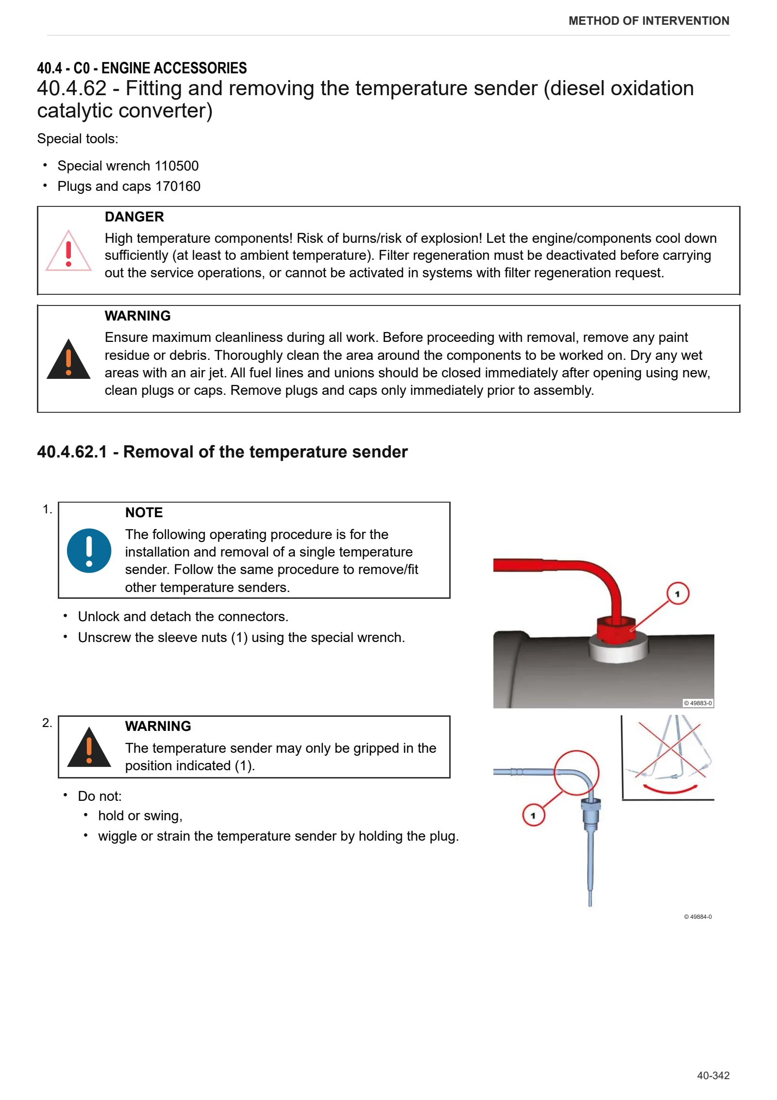
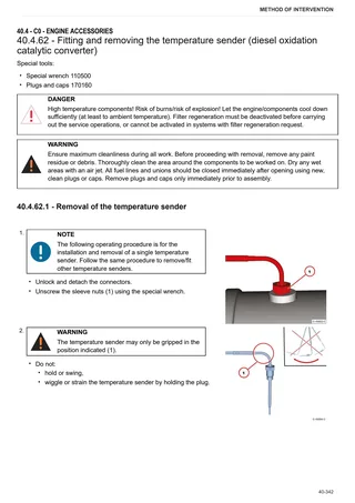
- Fitting and removing the temperature sender (diesel oxidation catalytic converter)
- Temperature sender (exhaust gas)
- Temperature sender (inlet air and ambient air temperature)
- Closing components
- Closing components
- Closing components
- Shield plate
- Fastener elements (wiring bundle)
- Fastener elements (wiring bundle)
- Support plate (on the charge air pipe)
- Mounting plate (on boost air hose)
- Cable harness (fastener elements)
- Protective cap (relay)
- Flushing the SCR (Selective Catalytic Reduction) delivery pump
- Flushing/Checking SCR (Selective Catalytic Reduction) metering unit
- Cover guard (Differential pressure transducer)
- Mount (exhaust backpressure sensor)
- Disassembling and assembling the heater
- Disassembling and assembling the heater
- Removing and fitting the charge air elbow pipe
- Disassembling and assembling the mixer pipe
- Disassembling and assembling the mixer pipe
- Disassembling and assembling the butterfly valve
- Disassembling and assembling the butterfly valve
- Disassembly and assembly of the flange
- Fitting (starter motor)
- Fitting (starter motor)
- Shield plate (starter motor)
- Shield plate (starter)
- Removing and refitting the diesel particulate filter
- Removing and refitting the diesel particulate filter (module size 9.5″)
- Fastener elements (exhaust aftertreatment system) (NOx sensor, temperature sender, diesel particulate filter differential pressure sender)
- Mount (module size 9.5”)
- V-Band clamp.
- VBand clamp (3″ exhaust pipe)
- VBand clamp (4″ exhaust pipe)
- Inlet module (module size 9.5″)
- Outlet module (module size 9.5″)
- Mixer pipe (threaded connection)
- Mixer pipe (threaded connection) SCR (Selective Catalytic Reduction)
- Mixer pipe (fastening element) SCR (Selective Catalytic Reduction)
- Removing and fitting the V-belt pulley (version with locking cone)
- Disassembling and assembling the console (ribbed V-belt, level 1)
- Alternator
- Alternator
- Removing and fitting the rotational speed sensor (crankshaft)
- Disassembling and assembling the crankshaft speed sensor (fasteners)
- Disassembling and assembling the crankshaft speed sensor (fasteners)
- Disassembly and refitting of the intake air pressure/temperature sender
- Fitting the pressure transducer (fuel pressure / lubricant oil pressure)
- Heater relay
- Disassembling and assembling the pressure transducer (exhaust back-pressure)
- Differential pressure sender (diesel particulate filter)
- Differential pressure sender (diesel particulate filter)
- Temperature sender (upstream of the SCR catalytic converter)
- Temperature sender (ahead of and after diesel oxidation catalytic converter)
- SCR (Selective Catalytic Reduction) solenoid valve
- Complete cooling pack
- Removing and installing the support console (Level 2)
- Removal and refitting of the alternator (ribbed V-belt, level 1)
- Removal and installation of the fuel lift pump
- Removal and refitting of the alternator (ribbed V-belt, level 2)
- Removal and refitting of fuel lines (fuel lift pump – pilot block)
- Removal and refitting of fuel lines (pilot block – high pressure pump)
- Removal and refitting of the common rail
- Removal and refitting of fuel lines (pilot block – fuel lift pump)
- Removal and refitting of fuel lines (rail, cylinder head, pilot block – fuel filter)
D0 – Transmission
- Changing the transmission oil
- Torsionally flexible coupling
- Draining oil
- Removing the electronics and transmission control unit
- Removing the TPT cable (Variant 1)
- Removing the control unit (TCU) (Variant 1)
- Removing the TPT cable (Variant 2)
- Removing the control unit (TCU) (Variant 2)
- Removing the TPT cable (Variant 3)
- Removing the control unit (TCU) (Variant 3)
- Removing the TPT cable (Variant 4)
- Removing the control unit (TCU) (Variant 4)
- Separating rear axle from main transmission
- Removing input shaft
- Removing the clutch housing from the transmission housing
- Removing and dismantling bearing cover
- Removing the clutches from the clutch housing
- Dismantling clutch (K2/K1)
- Dismantling clutch (K4/K3)
- Dismantling clutch (K5/KR)
- Removing lubrication pressure relief valve
- Removing and dismantling hydraulic shift system
- Dismantling pump drive
- Removing and dismantling front wheel drive
- Removing and dismantling crawler gear shift and main clutch
- Removing the pressure regulator
- Removing and dismantling hydraulic shift system (IRS)
- Removing oil supply
- Removing shift system (IRS)
- Removing shift system (manual)
- Removing and dismantling main shaft
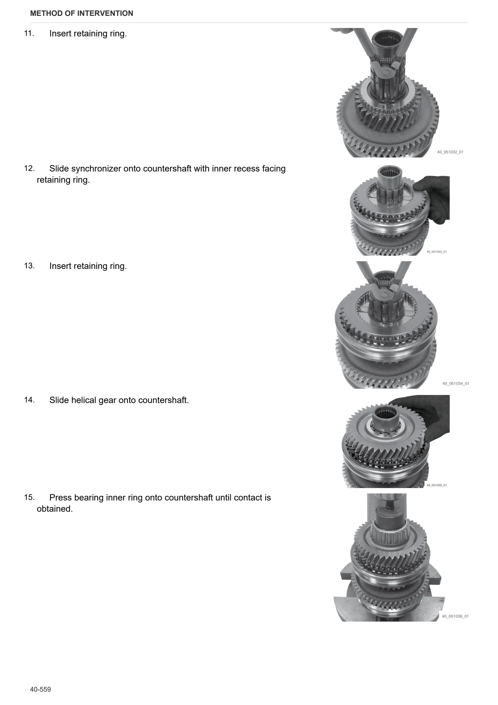
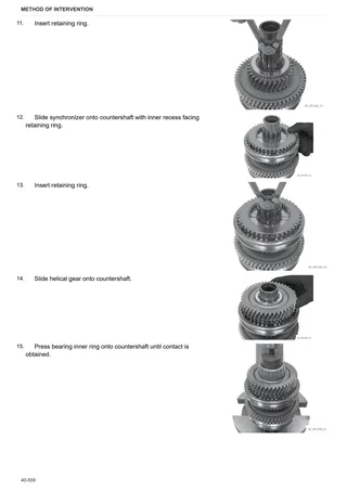
- Removing and dismantling countershaft
- Removing pump drive gear
- Assembling clutch (K2/K1)
- Assembling clutch (K4/K3)
- Assembling clutch (K5/KR)
- Installing clutches and mounting bearing cover
- Mounting and assembling hydraulic shift system
- Installing lubrication pressure relief valve
- Assembling the transmission housing
- Assembling and installing countershaft
- Installing main shaft
- Installing the shift system (IRS)
- Installing shift system (manual)
- Attaching the control unit (TUC)
- Assembling main clutch
- Installing main clutch and crawler gear shift system
- Assembling and installing front wheel drive
- Assembling and mounting pump drive
- Installing the pressure regulator and speed transmitter
- Assembling and installing hydraulic shift system (IRS)
- Mounting the clutch housing onto the transmission housing
- Installing input shaft
- Installing oil supply
- Adjusting crawler gear shift system
- Adjusting crawler gear shift system
- Closing components
- Mounting the electronics and the control unit
- Attaching the control unit (TUC) (variant 1)
- Installing the TPT cable (variant 1)
- Attaching the control unit (TUC) (variant 2)
- Installing the TPT cable (variant 2)
- Attaching the control unit (TUC) (variant 3)
- Installing the TPT cable (variant 3)
- Attaching the control unit (TUC) (variant 4)
- Installing the TPT cable (variant 4)
F0 – Front axle
- Safety precautions
- Oil Draining Mandatory Procedure
- Pivot brackets
- Planetary reduction gearbox and steering knuckle housing
- Stub axle and steering sensor
- Steering cylinders
- Differential assembly
- Conical pinion
- Oscillating pin
- Planetary reduction gearbox
- Stub axle and steering sensor
- Double universal joint
- Steering cylinder
- Bevel pinion
- Limited slip differential assembly
- Hydrolock differential assembly
- 4WD shaft
- Carrier with rear axle
- Under-sump reinforcement
G0 – Bodywork – Cab – Platform
- Cab – Configuration A
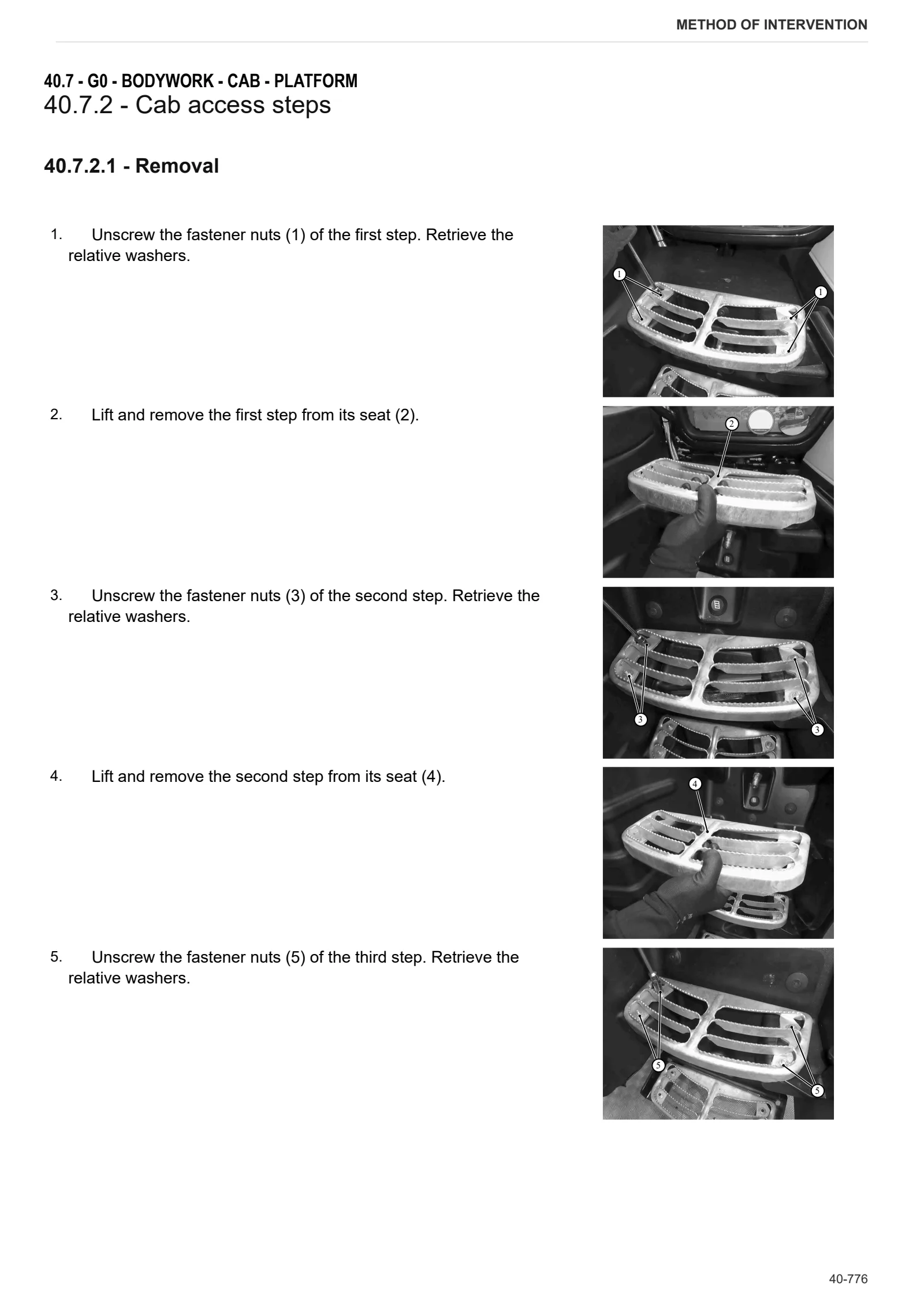
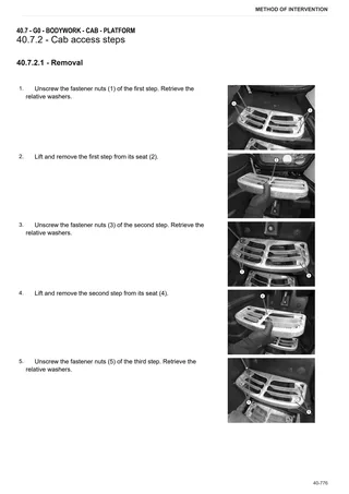
- Cab access steps
- Engine hood and front hood panels
- Battery mount
- Front mudguards
- Mat
- Under-seat mat
- Right hand console – Configuration A
- Left hand console
- Left hand pillar cover
- Right hand pillar cover
- Dashboard
- Instrument panel
- Roof panel
- Rear windscreen wiper motor
- Windscreen wiper electric motor
- Door handle
- Seat
- Passenger seat
- Empty and charge the air conditioning system
- A/C unit
- A.C. Electronic Control Unit replacement
- Air conditioner unit compressor
- Disassembling the A/C system compressor
- Air conditioning condenser
- Dehydrator filter
- Electronic throttle control
- Disassembling the electronic throttle control
- Clutch pedal
- Brake pedals
- Steering column
- Steering wheel
- Master cylinder
- Auxiliary utility distributor control levers
- Rear PTO control levers
H0 – Hydraulic system
- Hydrostatic steering (orbitrol)
- Front axle suspension solenoid valve block
- Brake system accumulator
- Disassembling the rear auxiliary utility distributors
- Brake control valve
- Steering system resonator
- Air braking system air filter
- Pneumatic trailer braking solenoid valves
- Right hand compressed air tank
- Left hand compressed air tank
L0 – Electrical system
- Connector cable (relay – alternator)
- Connector cable (relay – heater)
M0 – Front PTO
- Front PTO
- Front PTO shaft
N0 – Front lift
- Front lift
- Front lift arm carrier
- Front lift cylinders
- Front top link
R0 – Rear lift
- Aligning lift carriers
- Fitting lift position sensor
- Rear lift
- Rear lift hydraulic cylinders
- Rear lift arms
- Rear three-point linkage with hydraulic tie-rod
- Rear top link carrier
S0 – Wheels
- Front Wheels
- Rear wheel
V0 – Ballast – towing hitches
- Tow hook
Wiring diagrams
Wiring harnesses
- Wiring looms
Service Info
A0 – TRACTOR
- Diagnostics 2026 subscription
- After-sales 2026 subscription
- SERVICE NEWS RESEARCH GUIDE
- Diagnostics 2025 subscription
- After-sales 2025 subscription
- Diagnostics 2024 subscription
- After-sales 2024 subscription
C0 – ENGINE ACCESSORIES
- Possible Dust entry at air duct sleeve
- Diagnostic protocol – AdBlue – Float level unit
- Filter and prefilter tool p/n 5.9035.865.0
F0 – FRONT AXLE
- Bevel gear set loosing screws
G0 – BODYWORK – CAB
- MIRROR SUPPORT BREAKAGE
- Brake booster pump internal damage
H0 – HYDRAULIC AND PNEUMATIC SYSTEM|
- SERVICE NEWS – HPT – Front axle suspension – Damaged 2.8l accumulator
- Hydraulic CUNA trailer braking kit (ITALY)
- Single connection hydraulic braking kit availability update – only for EUROPEAN market
L0 – ELECTRIC AL SYSTEM
- SERVICE NEWS – New fixation for LED driving lights
- SERVICE NEWS – Software package release 2026-02
- Air pressure sensor malfunction
- PTO switch not working
R0 – REAR LIFT
- SERVICE NEWS – Series 6 TTV – introduction of longer WALTERSCHEID hydraulic toplink
- SERVICE NEWS – Series 6 TTV – Longer clevis for hydraulic toplink
- Series 6 TTV/TPT – Broken side stabilizer support screws
V0 – BALLAST, TOWING HITCHES
- SERVICE NEWS – Rear Hitch drawbar hole position
V1 – AFTERMARKET KITS
- Check correct installation of braking KIT
- Instructions for kit aftersales