Document overview
Workshop Manual for SAME SOLARIS 55 → ZKDAK40200MS30001 from the SOLARIS (STAGE 3A) family. Digital PDF in English with 819 pages.
The corresponding English table of contents contains 44 sections and 309 individual topics.
Main sections included
- Introduction
- Safety
- Technical characteristics
- Calibrations and electronic diagnosis
- Method of intervention
- Wiring diagrams
- Service Info
Document details
- Brand: SAME
- Family: SOLARIS (STAGE 3A)
- Model: SOLARIS 55
- Starting serial number: ZKDAK40200MS30001
- Document type: Workshop Manual
- Language: English
- Pages: 819
- File size: 187.97 MiB
- Format: Digital PDF download
Compatibility
Before purchasing, verify that your machine model and reference code match SAME SOLARIS 55 → ZKDAK40200MS30001.
Complete table of contents
Introduction
- Tightening Torques
- Pump tightening torques
- Wheel rim to hub screws and nuts tightening torques
- Tightening torques for nuts and bolts of electrical connections
- Installation of solenoid valves and cartridge valves
- Installation of quick couplers
- One-way valves
- Fixing the steering wheel
- Units of measurement and conversion factors
- Spool valves
Safety
Preface
- Important notes concerning safety
Important safety information
- Recognising hazards
- Indications for persons in contact with the tractor
Safety rules
- Risks during tractor preparation
- Risks during maintenance
- Work on machine systems
- Special disassembly/assembly/inspection procedures
Safety pictograms
- Replacing safety pictograms
Environmental risks
- Hazards associated with the operating environment
Technical characteristics
Transmission
- Transmission
- Rear PTO and Mid PTO
Rear axle
- Brakes and rear axle assembly
Front axle
- Front axle
Bodywork – Cab – Platform
- A/C system – Version with standard roof
- General introduction to the A/C system
- Changes of the state of matter
Hydraulic system
- STEERING/TRANSMISSION/UTILITIES hydraulic circuits
- Gear pump
- Differential lock control assembly
- Steering circuit
- Power steering valve
- Remote control valve
- Hydraulic lift control valve
Calibrations and electronic diagnosis
ECU alarms
- SDF Severity of alarms
- ECU ALARMS
Method of intervention
B0 – Engine
- PREPARATION FOR DISASSEMBLY
- Complete engine
- Separating engine from transmission
- Compression test
- engine block, crankshaft, pistons and sump
- Inspection of the engine monobloc
- Inspection of the crankshaft
- Fan – alternator drivebelt
- A/C fan – compressor drivebelt
- Crankshaft pulley
- Engine flywheel
- Flywheel bearing
- Timing gears and flywheel
- Inspection of the flywheel and ring gear
- Inspection of the pistons, piston rings and gudgeon pins
- Inspection of the connecting rods
- Inspection of the camshaft
- Inspection of the camshaft
- Inspection of the idler gear
- Inspection of the valves, valve guides and valve seats
- Valve clearances
- Inspection of the rocker arms and rocker shaft
- Cylinder head and valve train components
- Inspection of the cylinder head
- Inspection of the valve springs
- Inspection of the valve pushrods
- Renewal of the jets
- Lubrication System
- Inspection of the lubrication system
- Fuel System
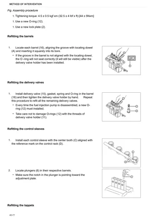
- Inspection and adjustment of the fuel system
- Inspection of the fuel lift pump
- Injection pump
- Inspection of the fuel injection pump camshaft
- Inspection of the fuel injection pump camshaft
- Fuel injection nozzle
- Maintenance of the injector nozzles
- Governor
- Cooling system
- Inspection of the cooling system
- Intake and exhaust systems
- Inspection of the air intake and exhaust system
C0 – Engine accessories
- Replacing the coolant
- Engine fan
- Coolant radiator
- Compensation tank
- Air filter box
- Air filter pipe
- Main fuel tank
- Main fuel tank float
- Auxiliary fuel tank
- Starter motor
- Starter motor
- Disassembly of the starter motor
- Alternator
- Alternator
- Engine stop keyswitch
- Engine stop keyswitch
- Exhaust silencer
- Exhaust pipe
D0 – Transmission
- Changing the transmission oil
- Disassembly of the gearbox input shaft
- Gearbox input shaft – oil seal renewal
- Disassembly of the main shaft
- Disassembly of the secondary shaft
- Range reduction gearbox shaft
- Front gearbox from its rear part
- Gearbox and shuttle assembly – complete unit
- Connector housing
- Creeper – synchronizer renewal
- Separating the gearbox housing from the rear gearbox housing
- Clutch unit
- Checking clutch plate wear
- Clutch release bearing
- Clutch release forks
- Bevel gear pair
- Adjustment of the bevel gear pair
- Disassembly of 4WD output shaft and groundspeed PTO
- PTO output shaft.
- Disassembly of the PTO output shaft.
- Removal of the PTO output shaft
- Parking brake
- Adjusting the parking brake
E0 – Rear axle
- Right-hand rear axle
- Left-hand rear axle
- Disassembly of LH/RH rear axle
- Rear differential
- Disassembly of the rear differential
- Rear axle brake discs
F0 – Front axle
- 4WD shaft
- Support with front axle
- Front axle
- Steering cylinder
- Steering cylinders disassembly
- Pinion-differential assembly
- Disassembly of the bevel gear pair
- Front half-axle
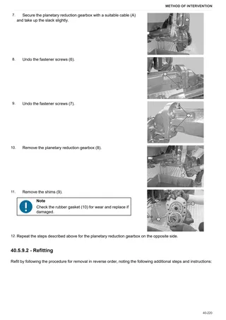
- Planetary reduction gearbox
- Disassembly of the planetary reduction gear
- Adjusting steering angle
G0 – Bodywork – Cab – Platform
- Cab
- Platform
- Lower hood guard
- Engine hood
- Engine hood mount
- Footboard guards
- Cab access steps
- Roll bar and mounts
- Battery mount
- Adjustable front fenders
- Cab door lock – tie-rod
- RH rear cab pillar trim
- Left-hand rear cab pillar – screenwash reservoir
- Instrument panel
- A/C system air intake filters
- Right hand console
- Remote valve control levers
- Adjusting brake pedal travel
- Adjusting the rear PTO clutch lever
- Clutch pedal adjustment
- Adjusting gear lever
- Adjustment of the lift control valve levers
- Instrument cluster
- Instrument cluster
- Lower instrument cluster
- Cab roof
- Air conditioning compressor
- Condenser
- Receiver-dryer
- Evaporator assembly
- Air conditioner fan
- Bistable pressure switch for compressor clutch engagement/disengagement
- Seat
- Steering wheel
H0 – Hydraulic system
- Lift, utilities and hydraulic steering pump
- Transmission oil filter assembly
- Power steering valve – Complete assembly
- Power steering disassembly
- Pressure relief valve – lift control valve
- Lift locking shut-off valve
- Remote control valve
- Remote control valve
- Control rods
- Double/single acting conversion valve
L0 – Electrical system
- Battery
- Fuse and relay assembly
- Electric clutch unit
- Parking brake switch
- Adjustment of the parking brake switch
- Brake lights switches
- Adjustment of the brake light switches
- Lateral light unit
- Steering column switch
M0 – Front PTO
- Pump – clutch assembly – brake
- PTO output shaft
- Solenoid valve
N0 – Front lift
- Front lift – version with front PTO –
- Cylinder
R0 – Rear lift
- Complete rear lift
- Rear lift – complete assembly
- Adjustment of the rear lift
- Sensing device mount
- Adjusting the sensing device tie-rod
- Lift cylinders
- Lift cylinders
- Renewal of the rear lift bush
- Lift arms
- Hydraulic lift control valve
- Disassembly of the lift control valve
- Three-point linkage with mechanical adjustment
S0 – Wheels
- Front Wheels
- Rear wheels
V0 – Ballast – towing hitches
- Rear towing hitch and carrier
- Support and towing hitch
Wiring diagrams
Introduction
- Introduction
- Basic electronics for mechanics (1/2)
- Basic electronics for mechanics (2/2)
- Electrical and electronic components (1/2)
- Electrical and electronic components (2/2)
Components
- A – Starting and charging
- B – Valves, fuses
- C – Grounds
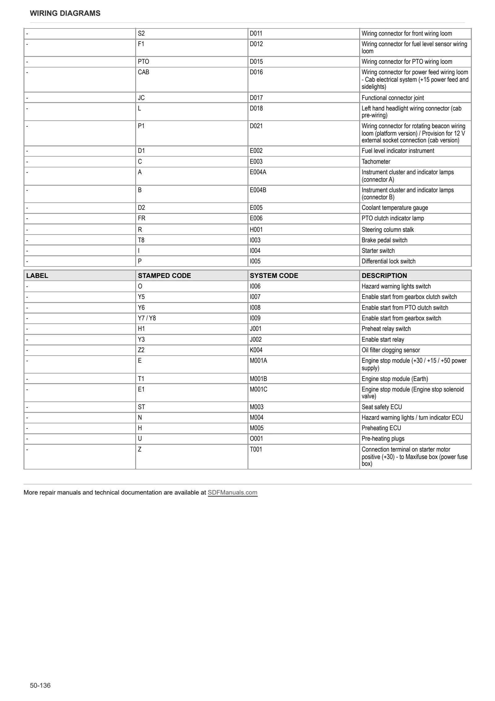
- D – Intermediate connections
- E – On-board instruments and visual and audible indicators
- F – External lights
- G – Interior lights
- H – Electrical and manual controls
- I – Circuit breakers
- J – Relays
- K – Sensors and transmitters
- L – Electromagnets and solenoid valves
- M – Electrical/electronic devices, flasher units and timers
- N – Electric motors/electronic devices, flasher units and timers
- O – Resistors and rheostats
- P – Various services
- Q – Safety devices
- T – Power supply points
Systems
- S001 – Power
- S002 – Starter
- S003 – Engine cooling (BARUFFALDI)
- S004 – Front lights / horn
- S005A – Rear lights (platform version)
- S005B – Rear lights (cab version)
- S006A – Turn indicators / hazard warning lights (platform version)
- S006B – Turn indicators / hazard warning lights (cab version)
- S007A – Work lights / rotating beacon (platform version)
- S007B – Work lights / rotating beacon (cab version)
- S008 – Front wiper (cab version)
- S009 – Rear wiper (cab version)
- S010 – Air conditioner (cab version)
- S011 – Internal lighting / radio / clock (cab version)
- S012 – Instrument cluster / indicators
- S013 – PTO
- S014 – Brake system
- S015 – Trailer socket
- S016 – Differential / 4WD
Wiring harnesses
- Wire colour reference table
- 0.012.6951.4/70 – Front wiring loom
- 0.012.6955.4 – PTO distribution
- 0.014.2645.4/10 – Front PTO
- 0.014.7599.4 – Front lights
- 0.015.0030.4 – Baruffaldi ECU
- 0.012.6949.4/40 – Central wiring loom
- 0.013.9918.4 – Fuel level sensors
- 0.013.1452.4/20 – Rear wiring loom
- 0.014.7593.4/20 – Cab
- 0.014.7594.4/10 – Cab power supply
- 0.014.7596.4 – Air conditioner
- 0.014.7601.4 – Air conditioning compressor
- 0.015.0031.4 – Ground cable for platform – cab interconnection
- 0.018.3547.4 – Seat wiring
- 0.008.0361.3 – Work light (platform version)
- 0.014.7595.4/10 – Cab lights
- 0.014.7598.4/10 – Windscreen wiper
- 0.014.7600.4 – Radio and ceiling light unit
- 0.007.6724.3/20 – Number plate light (platform version)
- 0.010.0003.3 – Rear lights (platform version)
- 0.014.7602.4 – Rear lights (cab version)
- 0.013.2605.4 – Rotating beacon (platform version)
- 0.014.7597.4 – Rotating beacon (cab version)
Service Info
A0 – TRACTOR
- Diagnostics 2026 subscription
- After-sales 2026 subscription
- SERVICE NEWS RESEARCH GUIDE
- Diagnostics 2025 subscription
- After-sales 2025 subscription
- Diagnostics 2023 subscription
- Diagnostics 2024 subscription
- Diagnostics 2022 subscription
- Diagnostics 2021 subscription
- After-sales 2024 subscription
- After-sales 2023 subscription
- After-sales 2022 subscription
- After-sales 2021 subscription
- After-sales 2019 subscription
- SDF Parts and SDF Service DVV 04/2014, version 26
- New function: Download PDF manuals
- Diagnostics – 2020 subscription
- After-sales – 2020 subscription
- After-sales – 2018 subscription
- Service and Spare Parts – 2017 Subscription
- SDF Parts and SDF Service DVDs 05/2014 version 25
B0 – ENGINE
- Flushing the lubrication circuit
- Deutz AG engine oil specifications
C0 – ENGINE ACCESSORIES
- Diagnostic protocol – AdBlue – Float level unit
- Filter and prefilter tool p/n 5.9035.865.0
D0 – TRANSMISSION
- Solaris input shaft oil seal leakages
E0 – REAR AXLE
- Solaris brake boot new P/N
F0 – FRONT AXLE
- Check the front axle steering knuckles for wear
- Steering behavior check procedure
G0 – BODYWORK – CAB
- Range lever accidental release – 2.0
- Range lever accidental release
- Air conditioning system recharging
H0 – HYDRAULIC AND PNEUMATIC SYSTEM|
- Hydraulic CUNA trailer braking kit (ITALY)
- Single connection hydraulic braking kit availability update – only for EUROPEAN market
- L0 – ELECTRIC AL SYSTEM