Document overview
Workshop Manual for SAME EXPLORER³ 85 T → ZKDR0202W0TS05001 from the EXPLORER³ T-TB (STAGE 3A) family. Digital PDF in English with 1,094 pages.
The corresponding English table of contents contains 36 sections and 333 individual topics.
Main sections included
- Introduction
- Safety
- Technical characteristics
- Method of intervention
- Service Info
Document details
- Brand: SAME
- Family: EXPLORER³ T-TB (STAGE 3A)
- Model: EXPLORER³ 85 T
- Starting serial number: ZKDR0202W0TS05001
- Document type: Workshop Manual
- Language: English
- Pages: 1,094
- File size: 169.80 MiB
- Format: Digital PDF download
Compatibility
Before purchasing, verify that your machine model and reference code match SAME EXPLORER³ 85 T → ZKDR0202W0TS05001.
Complete table of contents
Introduction
- Tightening Torques
- Pump tightening torques
- Wheel rim to hub screws and nuts tightening torques
- Tightening torques for nuts and bolts of electrical connections
- Installation of solenoid valves and cartridge valves
- Installation of quick couplers
- Units of measurement and conversion factors
Safety
Preface
- Important notes concerning safety
Important safety information
- Recognising hazards
- Indications for persons in contact with the tractor
Safety rules
- Risks during tractor preparation
- Risks during maintenance
- Work on machine systems
- Special disassembly/assembly/inspection procedures
Safety pictograms
- Replacing safety pictograms
Environmental risks
- Hazards associated with the operating environment
Technical characteristics
Engine
- Components of the 2012 2V UPS engine
- Test data and settings
- Tightening requirements 2012 2V UPS engine
- Components of the TCD 2012 L04/L06 2V DCR engine
- Test and adjustment data (L3)
- Tightening requirements TCD 2012 L04/L06 2V DCR engine
Transmission
- Transmission
- Transmission
- 2 and 4-speed PTO and Groundspeed PTO
- Hydraulic reverse shuttle
- Rear P.T.O.
Rear axle
- Rear differential
- Rear axle
Front axle
- Front axle 4 WD
Hydraulic system
- Braking system
- Separate-Brakes valve
- Trailer braking valve
- Power steering 125 cc
- Transfer pump
- Ancillary oil pump
- Power steering pump
- Suction pump filter
- Delivery line filter
- Distributor unit
- Pressure regulator valve unit
- Service valve unit
- Reverse shuttle control valve block
- Rear PTO
- Transmission hydraulic circuits
- Transmission hydraulic circuits
- Hydraulic distributor circuit
- Mechanical rear lift
Rear lift
- Rear lift distributor
Method of intervention
B0 – Engine
- Air conditioning compressor drive belt
- Tension adjustment of the fan and air conditioning compressor drive belt
- Alternator, fuel pump and water pump drive belt
- Tension adjustment of the alternator, fuel pump and water pump drive belt
- Check the compression value (L3)
- Assembly and disassembly of the engine on the assembly stand (L3)
- Valve clearance adjustment (with the exhaust gas recirculation module absent or removed) (L3)
- Valve clearance adjustment (with the exhaust gas recirculation module installed) (L3)
- Disassembly and assembly of the rocker and support (L3)
- Disassemble and complete the rocker and support, check
- Disassembly and assembly of the cylinder head (L3)
- Valve assembly and disassembly (L3)
- Valve check (L3)
- Check the valve guide (L3)
- Check the valve residual (L3)
- Crankshaft check (L3)
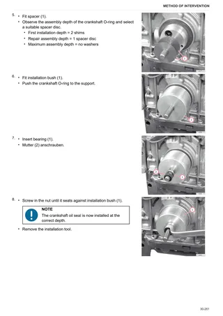
- Replace the crankshaft O-ring (flywheel end) (L3)
- Replace the crankshaft O-ring (opposite end to flywheel) (L3)
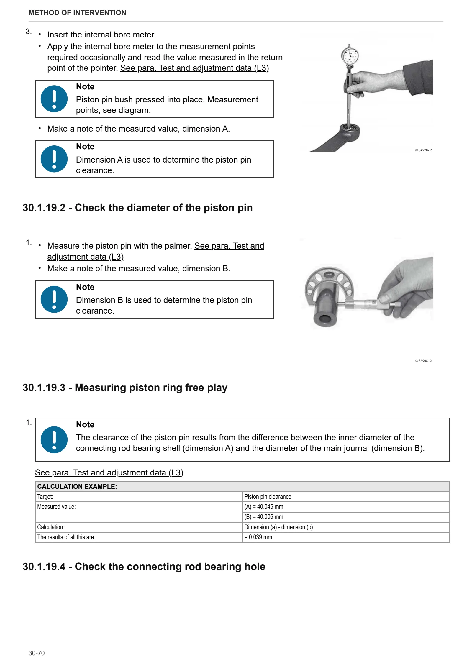
- Connecting rod drum check (L3)
- Assembly and disassembly of the crankshaft (L3)
- Disassembly and assembly of the piston and connecting rod drum (L3)
- Check the piston (L3)
- Check the piston rings and piston grooves (L3)
- Assembly and disassembly of the piston cooling nozzles (L3)
- Removing and fitting crankcase breather (L3)
- Checking cylinder (L3)
- Removal and refitting of the front cover (opposite end to flywheel) (L3)
- Disassembly and assembly of the connector box (L3)
- Disassembly and assembly of the gear case cover (L3)
- Assembly and disassembly of the camshaft (L3)
- Check the camshaft (L3)
- Disassembly and assembly of the turbocharger (L3)
- Disassembly and assembly of the turbocharging air duct (L3)
- Fitting and removing the exhaust gas recovery module (L3)
- Removing and fitting the fuel delivery pump (driven by ribbed V-belt) (L3)
- Removing and fitting the fuel control unit (L3)
- Removing and fitting high pressure pump (installation position A) (L3)
- Removing and fitting high pressure pump (installation position B) (L3)
- Removing and fitting the common rail system (L3)
- Removing and fitting injector (L3)
- Removing and fitting the pressure cut-off valve (L3)
- Removing and fitting the fuel pressure transducer (L3)
- Assembly and disassembly of the oil intake pipe (L3)
- Disassembly and assembly of the lubricant oil sump (L3)
- Disassembly and assembly of the oil radiator (L3)
- Removing and fitting the lubricant oil cooler housing (L3)
- Removing and fitting the lubricant oil filter (L3)
- Removing and fitting the oil pressure switch (L3)
- Removing and fitting reservoir (L3)
- Removing and fitting the coolant pump (driven by ribbed V-belt) (L3)
- Removing and refitting fan motor (L3)
- Removing and fitting fan motor (L3)
- Removing and fitting fan mount (L3)
- Disassembly and assembly of the torsional vibration damper (L3)
- Removing and fitting belt tensioner (ribbed V-belt) (L3)
- Assembly and disassembly of the flywheel (L3)
- Compression test
- Assembly and disassembly of the engine on the assembly stand
- Adjustment of valve clearance
- Removal and refitting of the rocker arms and pedestals
- Disassemble and complete the rocker and support, check
- Disassembly and assembly of the cylinder head
- Grinding the cylinder head seal surface
- Measuring piston protrusion
- Valve assembly and disassembly
- Valve check
- Check the valve guide
- Replacing the valve guide (oversized – cast)
- Check the valve residual
- Replacing the lined valve seat (oversized)
- Check the endfloat of the crankshaft
- Check the crankshaft
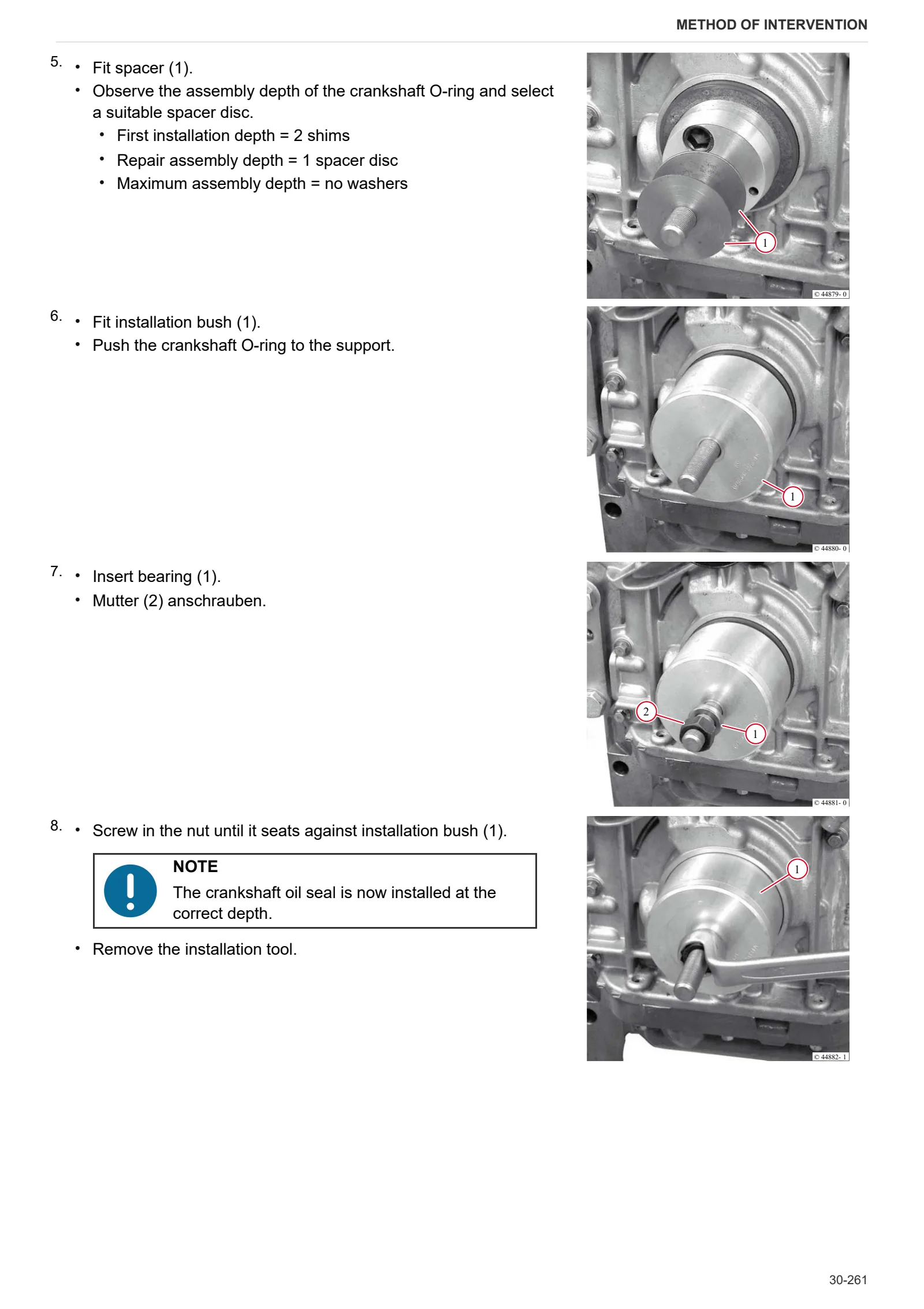
- Replace the crankshaft O-ring (flywheel end)
- Replacing the crankshaft O-ring (opposite end to flywheel)
- Check the connecting rod drum
- Fitting and removing piston pin bush
- Assembly and disassembly of the crankshaft
- Fitting and removing counterweight shafts, checking
- Disassembly and assembly of the piston and connecting rod drum
- Check the piston
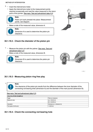
- Check the piston rings and piston grooves
- Assembly and disassembly of piston cooling nozzles
- Removal and refitting of the crankcase breather
- Check the cylinder
- Removal and refitting of the front cover (opposite end to flywheel)
- Disassembly and assembly of the connector box
- Fitting and removing the camshaft bearings, checking
- Disassembly and assembly of the gear case cover
- Assembly and disassembly of the camshaft
- Check the camshaft
- Removal and refitting of the rotation device
- Removing and fitting the V-belt pulley
- Fitting, removing, checking and setting adjuster rod
- Removal and refitting of the turbocharger
- Removal and refitting of the charge air duct
- Fitting and removing injection pump
- Determine the thickness of the shim (engine without injection advance variator)
- Determine the thickness of the shim (engine with injection advance variator)
- Determination of the overall dimensions of the injection pump (engine without the injection advance variator)
- Determination of the overall dimensions of the injection pump (engine with the injection advance variator)
- Fitting and removing injection valves
- Checking the injection valves
- Removal and refitting of the fuel lift pump
- Removal and refitting of the oil pickup pipe
- Removing and fitting the lubricant oil sump pan (cast iron lubricant oil sump)
- Disassembly and assembly of the lubricant oil sump (lubricant oil sump-plate)
- Removal and refitting of the oil cooler
- Disassembly and assembly of the oil radiator housing
- Removal and refitting of the oil pressure switch
- Removal and refitting of the water pump
- Removal and assembly of the fan support
- Removal and refitting of the fan support
- Removal and refitting of the flywheel
- Replacing the starter motor ring gear on the flywheel
C0 – Engine accessories
- Engine coolant replacement
- Engine cooling fan
- Engine coolant radiator
- Radiator assembly
- Expansion tank
- Transmission oil radiator and intercooler
- Air filter container
- Fuel tank
- Exhaust silencer
- Exhaust pipe
- Removing and refitting the exhaust manifold (L3)
- Removal and refitting of the exhaust manifold
- Removal and refitting of the alternator (with drivebelt)
- Removing and fitting the engine governor
- Disassembly and assembly of the starter
- Disassembly and assembly of the starter (L3)
- Removing and fitting the alternator (driven by ribbed V-belt) (L3)
- Fitting and removing the solenoid valve (exhaust gas recovery module) (L3)
- Fitting and removing the glow plugs (L3)
- Removal and refitting of the supply air pressure/temperature sender (L3)
- Removing and fitting the fuel filter mount (L3)
- Assembly and disassembly of the temperature sender (L3)
D0 – Transmission
- Changing the transmission oil
- Gearbox and shuttle assy. – complete unit
- Disassembling the range selector assembly
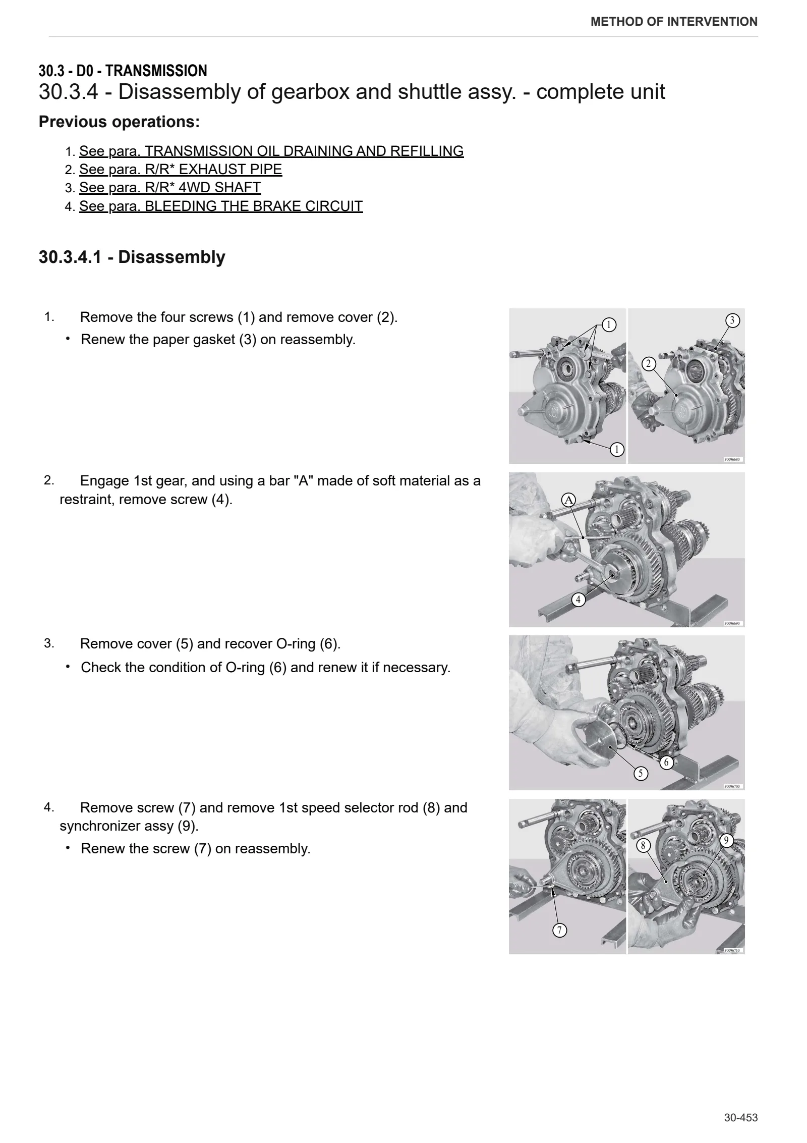
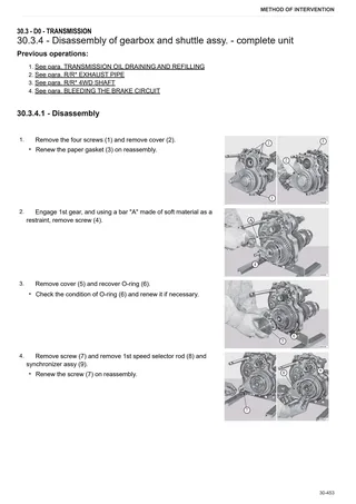
- Disassembly of gearbox and shuttle assy. – complete unit
- Clutch plate
- Shuttle shaft
- Gearbox internal cover
- Disassembling the primary shaft – Version without range selection
- Disassembly of the secondary shaft – Version without Hi-Lo
- Adjustment of the differential – Bevel gear set
- Removing the rear pinion – 2-range version
- PTO clutch
- PTO clutch disassembly
- Rear PTO output flange shaft
- Adjustment of the Differential – Bevel gear pair
- Gearbox support and gear selector rods
- Clutch housing – assembly
- DT shaft in transmission
- Removing dual traction output shaft 2-range version
- Range selector assembly
- Differential – Bevel gear set
- Clutch housing – Separation from transmission
- Pump drive PTO – Inner gear
- Pump drive PTO – Outer gear
- PTO output shaft – 2 speed version
- Disassembly of the PTO output shaft – 2-speed version
- Disassembly of the PTO output shaft – 4-speed version
- Parking brake
- Disassembly of the parking brake
- 4WD engagement device
E0 – Rear axle
- Bleeding air from the hydraulic circuit of the front and rear brakes
- Rear axle brake discs
- Disassembly of the rear axle brake piston
- LH rear axle
- RH rear axle
- Disassembly of LH/RH rear axle
- Disassembly of the planet carrier
- Disassembly of the rear differential
- Rear differential
F0 – Front axle
- 4WD shaft
- Separating front carrier from engine
- Front axle (4WD)
- Steering cylinders
- Removing steering cylinders
- Differential assembly
- Disassembling the differential assembly
- Bevel gear set
- Disassembly of the differential
- Adjustment of the bevel gear set
- Differential assembly adjustment
- Front axle adjusting endfloat
- Planetary reduction gearbox
- Disassembly of the planetary reduction gearbox
- Steering knuckle housing and half-shaft
- Adjustment of steering knuckle housing and axle shaft
- Front brake discs
- Front axle brake piston
G0 – Bodywork – Cab – Platform
- Roll bar
- Mat and footboards
- Engine cowl
- Engine hood mount
- Cowl frame
- Battery mount
- Driver access steps
- Right hand console
- Lift control levers
- Rear mudguard
- Seat
- Seat mounting plate
- Steering wheel
- Instrument cluster
- Steering column
- Front mudguards
- Brake master cylinder
H0 – Hydraulic system
- Lift and ancillary utility distributor circuit pump.
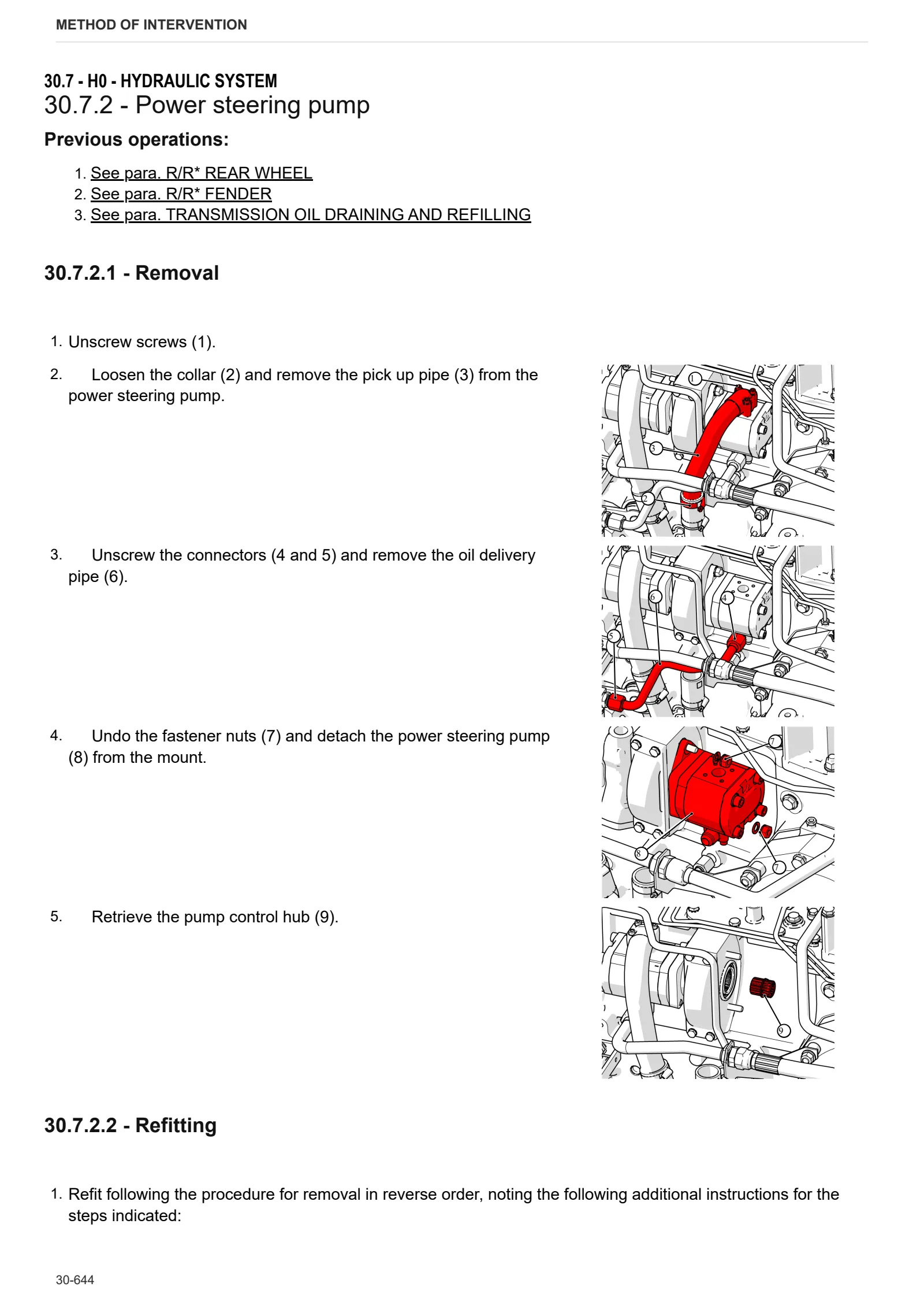
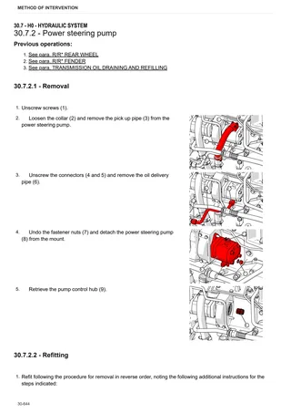
- Power steering pump
- Transmission oil transfer pump
- Power steering
- Rear ancillary distributor
- Ancillary solenoid valve block
- Disassembling the ancillary solenoid valve block
- Shuttle solenoid valves assembly
- Disassembling shuttle solenoid valve block
- Trailer hydraulic braking valve
- Bleeding the braking circuit
L0 – Electrical system
- Alternator
- Battery – Version without front PTO
- Clutch pedal potentiometer
- Throttle pedal potentiometer
- Hydraulic reverse shuttle output speed sensor
- Instrument cluster
- Battery master switch
- Steering column stalk
- Reverse shuttle control unit and drive direction selector
R0 – Rear lift
- Mechanical rear hitch control
- Disassembly of the lift – complete assembly
- Auxiliary lift cylinders
- Rear ancillary distributor
- Disassembly of the lift control valve
- Mechanical draft sensor
- Mechanical draft sensor disassembly
- Replacing positioning for automatic release
- 3-point linkage
S0 – Wheels
- Front wheel
- Rear wheel
V0 – Ballast – towing hitches
- Swinging rear tow hitch
V1 – AFTERMARKET KITS
- Head and pin kit assembly procedure for automatic hitch
Service Info
A0 – TRACTOR
- Diagnostics 2026 subscription
- After-sales 2026 subscription
- SERVICE NEWS RESEARCH GUIDE
- Diagnostics 2025 subscription
- After-sales 2025 subscription
- Diagnostics 2023 subscription
- Diagnostics 2024 subscription
- Diagnostics 2022 subscription
- Diagnostics 2021 subscription
- Technical Documentation DVD 06/2009
- SDF LUBRICANTS: Lubricant oils and coolant fluids
- After-sales 2024 subscription
- After-sales 2023 subscription
- After-sales 2022 subscription
- After-sales 2021 subscription
- After-sales 2019 subscription
- SDF Parts and SDF Service DVV 04/2014, version 26
- Technical Documentation DVD 03/2010
- New function: Download PDF manuals
- Diagnostics – 2020 subscription
- After-sales – 2020 subscription
- After-sales – 2018 subscription
- Service and Spare Parts – 2017 Subscription
- SDF Parts and SDF Service DVDs 05/2014 version 25
- SDF Parts and SDF Service DVDs 03/2013 version 24
B0 – ENGINE
- Flushing the lubrication circuit
- Deutz AG engine oil specifications
- SerDia 2010 updating license file
- POSSIBLE LEAKAGE OF FUEL INTO THE ENGINE SUMP (LEVEL RISE)
C0 – ENGINE ACCESSORIES
- Diagnostic protocol – AdBlue – Float level unit
- Filter and prefilter tool p/n 5.9035.865.0
- Additive for diesel fuel
D0 – TRANSMISSION
- Twisted parking brake lever
- Bushes on shuttle input shafts
F0 – FRONT AXLE
- Check the front axle steering knuckles for wear
- Steering behavior check procedure
G0 – BODYWORK – CAB
- Clutch pedal potentiometer actuator pin
- Air conditioning system recharging
H0 – HYDRAULIC AND PNEUMATIC SYSTEM|
- Hydraulic CUNA trailer braking kit (ITALY)
- Single connection hydraulic braking kit availability update – only for EUROPEAN market
- Assembly instructions for solenoid valves and cartridge valves
- L0 – ELECTRIC AL SYSTEM