

Document overview
Digital Workshop Manual documentation for model LAMBORGHINI TCD 4.1 L04 Stage 4 (3B) from the Tractor components – Engine – DEUTZ AG Stage 3 family. Language: English; 944 pages.
The corresponding English table of contents contains 12 sections and 340 individual topics.
Main sections included
- Introduction
- Technical characteristics
- Calibrations and electronic diagnosis
- Method of intervention
Document details
- Brand: LAMBORGHINI
- Family: Tractor components – Engine – DEUTZ AG Stage 3
- Model: TCD 4.1 L04 Stage 4 (3B)
- Document type: Workshop Manual
- Language: English
- Pages: 944
- File size: 107.78 MiB
- Format: Digital PDF download
Compatibility
Before purchasing, verify that your machine model and reference code match LAMBORGHINI TCD 4.1 L04 Stage 4 (3B).
Complete table of contents
Introduction
- Introduction – Engines
- Tightening Torques
Technical characteristics
Engine
- Motor description – construction type
- Engine description – Images of engine
- Engine description – Lubricant oil diagram
- Engine description – Fuel circuit diagram
- Engine description – Coolant diagram
- Engine description – Exhaust gas recovery
- Engine description – Exhaust gas after-treatment
- Engine description – Electrical/electronic system
- Use – Environmental conditions
- Use – First start-up
- Usage – Starting procedure
- Usage – Controlling engine operation
- Use – exhaust gas after-treatment systems
- Usage – Active regeneration
- Usage – Passive regeneration
- Use – Stop procedure
- Operating materials – lubricant oil
- Operating materials – Fuel
- Operating materials – Coolant
- Fluids – SCR reduction agent
- Maintenance – Maintenance schedule
- Care and maintenance work – Lubricant oil system
- Care and maintenance work – Fuel distribution system
- Care and maintenance – SCR
- Care and maintenance work – Cooling system
- Care and maintenance work – Engine cleaning
- Care and maintenance work – Intake system
- Care and maintenance work – Belt transmissions
- Care and maintenance – Adjustments and settings
- Care and maintenance work – Electrical system
- Malfunctions – Malfunction table
- Faults – Engine management
- Transport and storage – Transport
- Transport and storage – Transport and storage
- Technical data – Engine data and adjustment data
Engine accessories
- Pressure transducer (L3)
- Technical data – Pressure transducer
- Pressure sensor (L3)
- Technical data – Pressure sensor
- Technical data – Pressure/temperature transmitter
- Temperature sender (L3)
- Technical data – Temperature transmitter
- Temperature sender (L3)
- Technical data – Temperature transmitter
- Temperature sender (L3)
- Technical data – Temperature sender
- Speed indicator (L3)
- Technical data – Speed indicator
- Technical data – Speed indicator
- NOx sensor (L3)
- NOx sensor (L3)
- Technical data – NOx sensor
- technical specifications – NOx sensor (12 V)
- Temperature sender (L3)
Calibrations and electronic diagnosis
Diagnostic tools
Serdia 2010
- Safety-Hints
- Common Hints
- Common Hints – Start and Communication
- Common Hints – Disposability
- Introduction
- Error Hints (FAQ)
- Connection establishment
- Software handling
- Software handling – Topper elements
- Global Programfunctionality – Dataset management
- Global Programfunctionality – Error memory
- Global Programfunctionality – Graphical display
- Global Programfunctionality – Program adjustments
- UseCases EMR4
- Engine settings
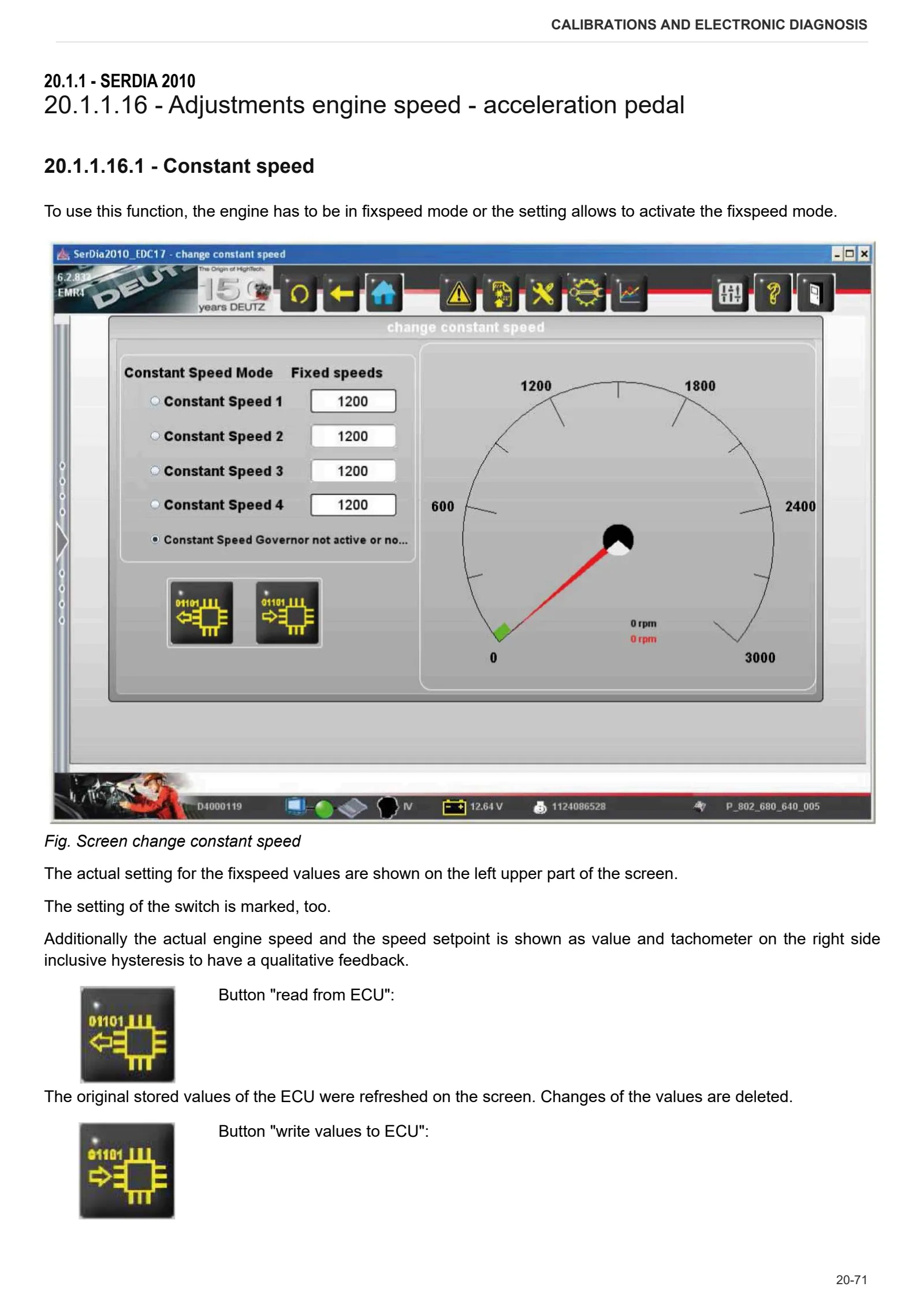
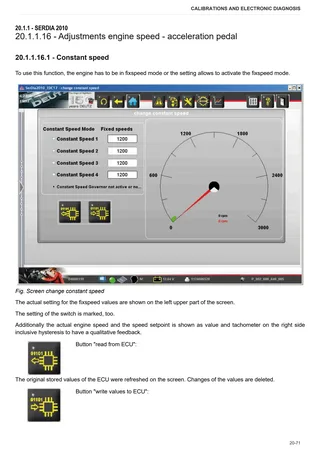
- Adjustments engine speed – acceleration pedal
- Exhaust after treatment
- CRT – TIER4 interim
- DPF – Burner – TIER4 interim
- SCR – TIER4 interim
- SCRT -TIER4 final
- EOL Test (Tier4F)
- SCR service routines
- DPF service routines
- Service Routines DPF (DOC/SCR)
- Service-Cases
- Other
- UseCases EMR3
- UseCases EMR2
- Programm options
ECU alarms
Engine alarms
- Engine ECU Alarms: SPN 000016-000175
- Engine ECU Alarms: SPN 000190-001188
- Engine ECU Alarms: SPN 001231-003520
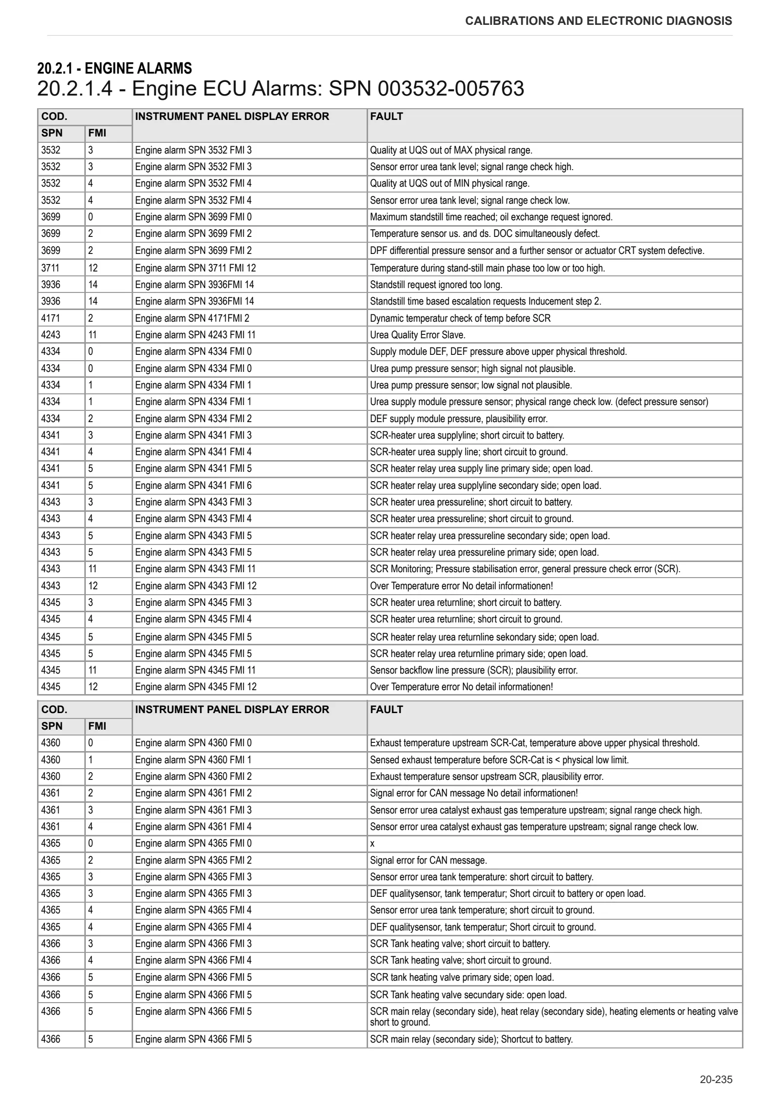
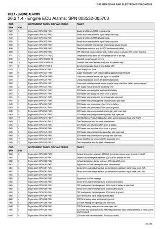
- Engine ECU Alarms: SPN 003532-005763
- Engine ECU Alarms: SPN 520521-523632
- Engine ECU Alarms: SPN 523633-523918
- Engine ECU Alarms: SPN 523919-524030
- Engine ECU Alarms: SPN 524031-524108
- Engine ECU Alarms: SPN 524109-524267
Method of intervention
- Tools for engine disassembly and reassembly
- Workshop tools for engine disassembly and reassembly (Lv.2)
B0 – Engine
- Checking crankcase pressure
- Removal and refitting of the crankcase breather
- Removal and refitting of the crankcase breather
- Disassembling and assembling crankcase breather
- Removing and fitting breather pipe (crankcase breather)
- Pipe (crankcase breather)
- Replacing crankshaft ring seals
- Replace the crankshaft O-ring (flywheel end)
- Replacing the crankshaft O-ring (opposite end to flywheel)
- Fitting/removing shaft sleeve from crankshaft
- Disassembling/assembling crankshaft wear sleeve (side opposite flywheel)
- Removal and refitting of the front cover (fixing elements)
- Disassembling and assembling the front cover (fixing elements)
- Closing components
- Blanking tool (crankcase)
- Blanking tool (crankcase)
- Blanking tools (crankcase, electronic engine governor)
- Blanking elements (crankcase, PTO-A)
- Blanking elements (crankcase, PTO-A)
- Blanking elements (PTO-B)
- Blanking elements (PTO-B)
- Oil filler neck
- Disassembly and assembly of the lubricant oil sump (lubricant oil sump-plate)
- Removing and fitting lubricant oil sump (heavy version)
- Removing and fitting lubricant oil sump (heavy version)
- Removing and fitting lubricant oil sump (heavy version)
- Disassembling and assembling the oil suction pipe
- Removal and refitting of the V-belt pulley
- Removal and refitting of the V-belt pulley
- Removing and fitting the V belt pulley/poly-V belt pulley
- Removal and refitting of the flywheel (fixing elements)
- Removal and refitting of the flywheel (fixing elements)
- Disassembling and assembling the flywheel (fixing elements)
- Replacing the starter ring gear on the flywheel (L3)
- Replacing the starter motor ring gear on the flywheel
- Compression test
- Compression test
- Removal and refitting of the cylinder head cover
- Removing and fitting the cylinder head cover
- Disassembly and assembly the cylinder head (fastening elements) (L3)
- Disassembling and assembling the cylinder head (fasteners)
- Measuring piston protrusion (L3)
- Measuring piston protrusion
- Assembly and disassembly of the valves
- Checking valves, valve guides, valve springs and valve recess
- Blanking elements (cylinder head)
- Blanking elements
- Eye-bolt for transporting (cylinder head)
- Disassembling and assembling the lubricant oil cooler
- Removing and fitting the oil radiator (fastener elements)
- Removal and refitting of the lube oil cooler housing
- Disassembling and assembling the lube oil cooler housing
- Removing and refitting lubricant oil cooler housing (fastener elements)
- Fitting the pressure transducer (lubricant oil pressure)
- Blanking elements (lubricant oil cooler housing)
- Heater connector (Lubricant oil cooler housing)
- Disassembly and assembly of the fuel control unit (fastening elements)
- Disassembly and assembly of the fuel control unit (fastening elements)
- Disassembly and assembly of the fuel control unit (fastening elements)
- Disassembly and assembly of the fuel control unit (fastening elements)
- Disassembly and completion of the pilot unit (L3)
- Disassembly and completion of the fuel control unit
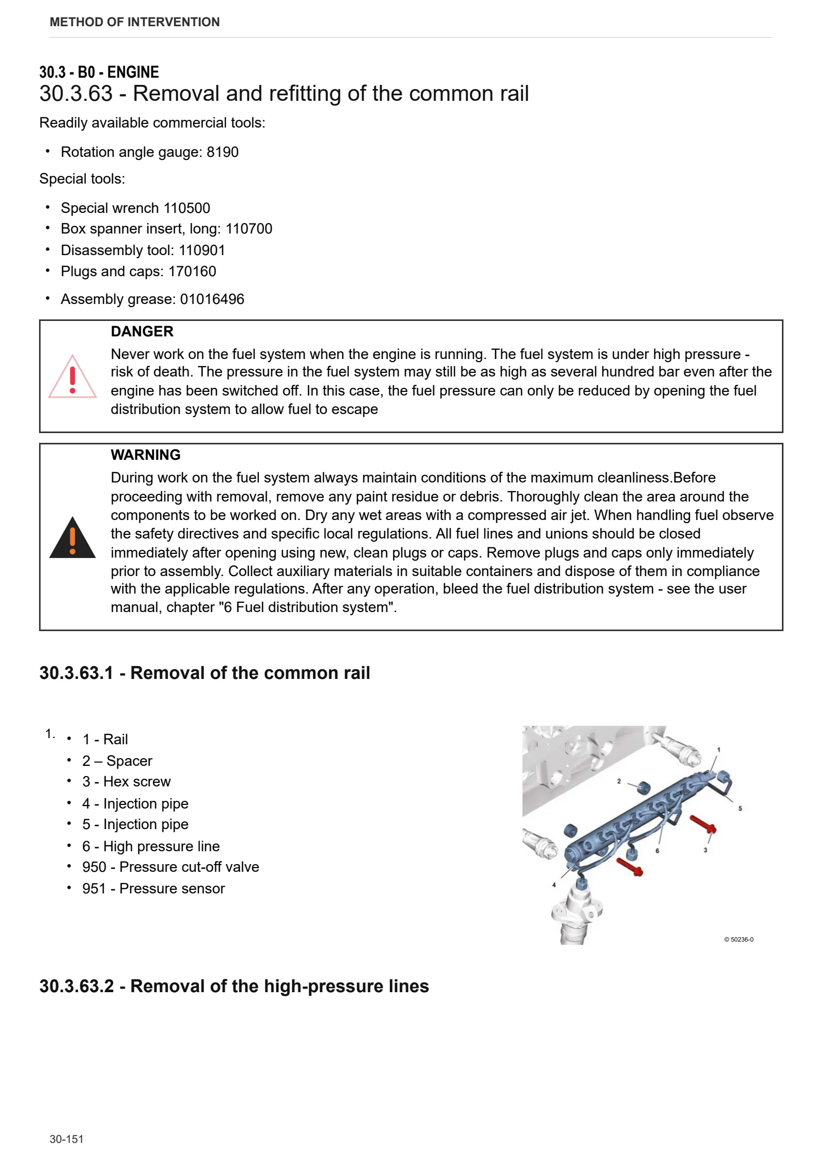
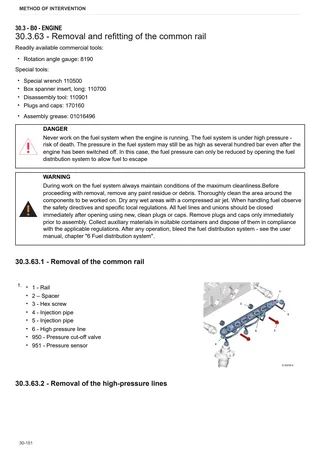
- Removal and refitting of the common rail
- Disassembling and assembling the rail (1600 bar injection system)
- Removing and fitting the pressure cut-off valve (rail)
- Removing and fitting the rail pressure sensor
- Fitting and removing the high pressure pump (fastener elements)
- Disassembling and assembling the high pressure pump (fastener elements)
- Removal and refitting of the injectors
- Removal and refitting of the injectors
- Disassembling and assembling the injector (1600 bar injection system)
- Replacing the injector bush
- Clean the injector bush
- Clean the injector bush seat
- Removal and refitting of the charge air duct
- Disassembling and assembling charge air pipe
- Removal and refitting of the charge air manifold
- Removal and refitting of the water pump
- Removing and fitting the coolant pump
- Transmission components (coolant pump)
- Removing and fitting the coolant pump (fastener elements)
- Mount (cylinder head, exhaust gas recovery, coolant pipe)
- Removal and refitting of the thermostat
- Assembling and disassembling the thermostat
- Testing the thermostat (after removal)
- Check the thermostat (after removing)
- Removal and installation of the thermostat housing
- Removal and installation of the thermostat housing
- Removing and fitting the thermostat housing (fastener elements)
- Blanking elements (thermostat housing)
- Blanking elements (thermostat housing)
- Blanking elements (thermostat housing)
- Blanking screws (thermostat housing)
- Hose connector (thermostat housing)
- Connection (Compensation tank)
- Removal and refitting of the belt tensioner (ribbed V-belt, level 1)
- Removal and refitting of the belt tensioner (ribbed V-belt, level 1)
- Disassembly and refitting of the belt tensioner (ribbed V-belt, level 1)
- Removing and fitting the mounting plate (ribbed V-belt, level 1)
- Removing and fitting the mounting plate (ribbed V-belt, level 1)
- Disassembling and assembling the console (ribbed V-belt, level 1)
- Removing and fitting the fan mount (fastener elements)
- Removing and fitting the fan mount (fastener elements)
- Removal and assembly of the fan support
- Removal and assembly of the fan support
- Removal and assembly of the fan support
- Removal and assembly of the fan support
- Disassembling and assembling the exhaust manifold
- Intake manifold (exhaust gas turbocharger)
- Removal and refitting of the turbocharger
- Disassembling and assembling the turbocharger
- Removal and refitting of the lubricating oil pipe (exhaust gas turbocharger)
- Removal and refitting of the lubricating oil pipe (exhaust gas turbocharger)
- Disassembling and assembling the lubricating oil pipe (exhaust gas turbocharger)
- Removal and refitting of the lubricating oil return pipe (exhaust gas turbocharger)
- Removing and refitting the lubricant oil return pipe – (upper section) – (turbocharger)
- Assembly and disassembly of the piston cooling nozzles (L3)
- Assembly and disassembly of piston cooling nozzles
- Assembly and disassembly of piston cooling nozzles
- Fitting and removing counterweight drive system, checking (L3)
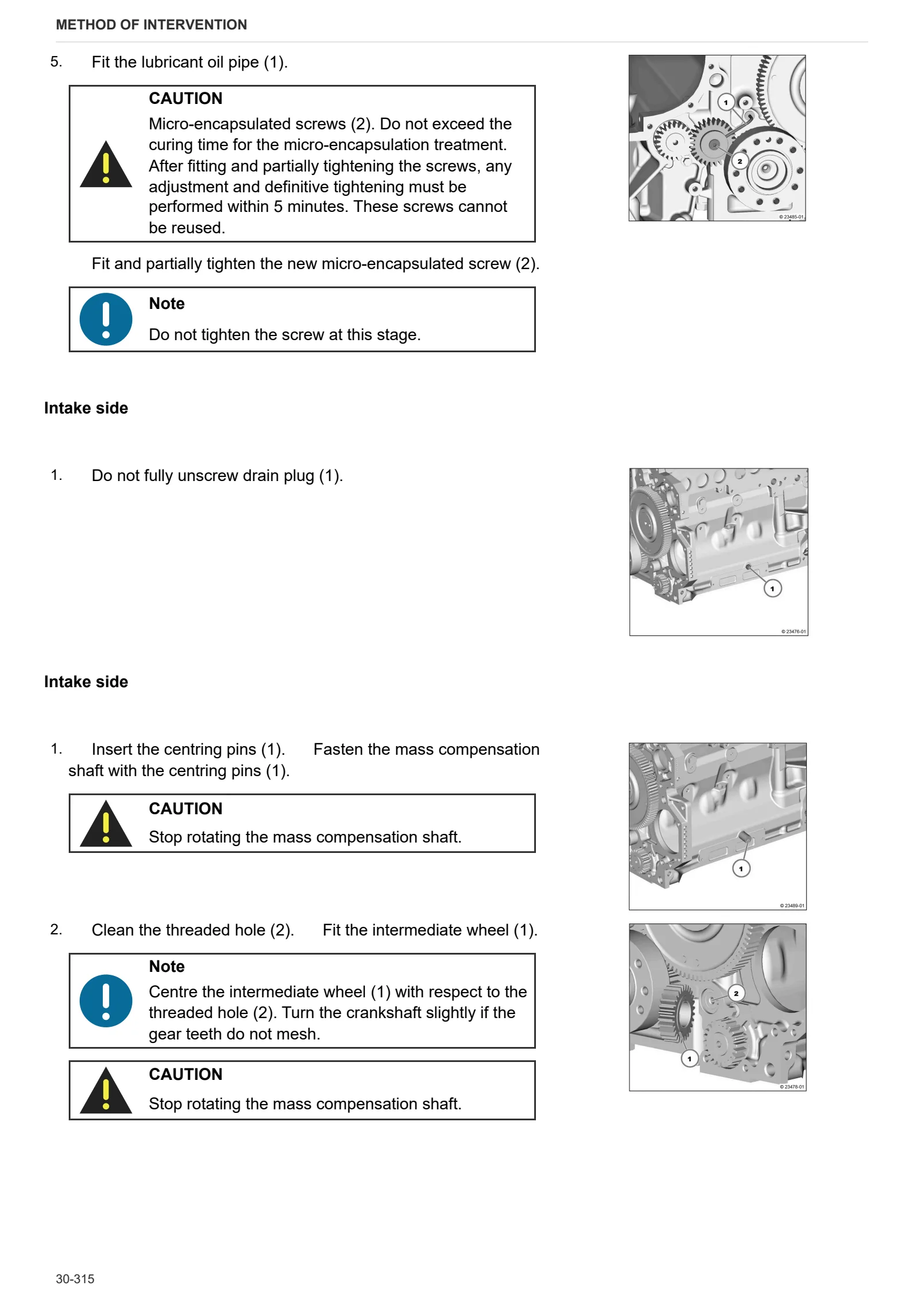
- Removing and fitting the counterweight shaft.
- Checking counterweight shafts
- Removing and fitting the counterweight drive shaft
- Disassembling and assembling the sensor wheel
- Assembly and disassembly of the crankshaft (L3)
- Removing and fitting the crankshaft
- Crankshaft check (L3)
- Check the crankshaft
- Check the endfloat of the crankshaft (L3)
- Check the endfloat of the crankshaft
- Fitting and removing crankshaft bearings (L3)
- Assembly and disassembly of the crankshaft bearing
- Check the crankshaft bearings (L3)
- Check the crankshaft bearings
- Assembly and disassembly of the connecting rod drum (L3)
- Disassembly and reassembly of connecting rod shank
- Connecting rod drum check (L3)
- Check the connecting rod shank
- Disassembling and assembling the piston
- Check the piston
- Disassembling and assembling the piston rings
- Check the piston rings
- Check the piston rings
- Disassembly and assembly of the gear box (L3)
- Disassembly and assembly of the gear box (L3)
- Disassembling and assembling the gearbox
- Assembly and disassembly of the camshaft (L3)
- Assembly and disassembly of the camshaft
- Check the camshaft (L3)
- Check the camshaft
- Checking the camshaft bearing
- Assembly and disassembly of the distribution valve (L3)
- Removing and fitting the valve timing system
- Removing and refitting the valve timing system
- Assembly and disassembly of the control elements (L3)
- Disassembly and assembly of the control elements
- Check and adjust valve clearances
- Checking and setting valve clearance (4 cylinder)
- Closing components
- Closing components
- Closing components
- Removal and refitting of the heater
- Removing and fitting the heater
- Disassembling and assembling the heater
- Disassembling and assembling the heater
- Actuating elements
- Hole blanking screw
- Port
- Fastening elements
- Pipe (burner, exhaust gas back-pressure sensor)
- Disassembly and assembly of the connector box
- Disassembly and assembly of the connector box
- Mount (exhaust gas back-pressure sensor)
- Fitting and removing the rotation device
C0 – Engine accessories
- Oil measuring device
- Sleeve
- Cover
- Belt drive
- Engine suspension
- Engine suspension (cylinder head)
- Removing and fitting the fuel delivery pump (fastener elements)
- Disassembling and assembling the fuel delivery pump (fastener elements)
- Manual fuel pump
- Fuel prefilter
- Fuel filter
- Fuel filter
- Assembly of the pressure transducer (fuel pressure)
- Fuel pipe (fuel control unit)
- Removal and refitting of fuel lines (fuel lift pump – pilot block)
- Removing and fitting the fuel pipe (fuel control block – high pressure pump)
- Disassembling and assembling the fuel line (fuel control block – high pressure pumps)
- Fuel pipe (fuel delivery pump, fuel filter, fuel control block, rail, cylinder head)
- Fuel pipes (fuel delivery pump, fuel filter, fuel control block, rail, cylinder head)
- Removing and fitting fuel lines (fuel delivery pump, fuel filter, fuel control unit, rail, cylinder head)
- Removal and installation of the exhaust pipe (auxiliaries)
- Disassembly and assembly of the alternator (ribbed V-belt, level 1).
- Disassembly and assembly of the alternator (ribbed V-belt, level 1).
- Disassembling and assembling alternator (poly-V-belt, level 1)
- Alternator
- Alternator
- Removing and fitting the V belt pulley/poly-V belt pulley (alternator)
- Removing and fitting the starter (fastener elements)
- Connection (Starter)
- Connection (Starter)
- Shield plate
- Shield plate (starter)
- Starter (fasteners)
- Mount (Assembly foot, side opposite of the flywheel)
- Mount (assembly foot, side opposite of the flywheel)
- Mount (assembly foot, flywheel side)
- Components
- Components
- Fastening elements
- Removing and refitting the crankshaft speed sensor
- Removing and fitting the camshaft speed sensor (ancillaries)
- Disassembling and assembling the camshaft speed sensor (ancillaries)
- Disassembly and refitting of the intake air pressure/temperature sender
- Wiring harness (fasteners)
- Wiring harness (fasteners)
- Mount (fasteners)
- Temperature sender (coolant)
- Fitting the pressure transducer (fuel pressure / lubricant oil pressure)
- Disassembling and assembling the thermostat
- Relay (heater, thermo-starter, glow plugs)
- Heater (connector line)
- Mount (relay)
- Temperature sender
- Covering case
- Covering case
- Removing and fitting the NOx sensor
- Disassembling and assembling the NOx sensor
- Assembling the SCR (Selective Catalytic Reduction) metering unit
- SCR delivery pump (Selective Catalytic Reduction)
- Flushing the SCR delivery pump (Selective Catalytic Reduction)
- Flushing/Checking SCR (Selective Catalytic Reduction) metering unit
- Flushing the SCR (Selective Catalytic Reduction) pipe (delivery pump – metering unit)
- Fitting and removing the temperature sender (diesel oxidation catalytic converter)
- Temperature sender (exhaust gas)
- Temperature sender (inlet air and ambient air temperature)
- Closing components
- Closing components
- Closing components
- Shield plate