
Document overview
Workshop Manual PDF for LAMBORGHINI TCD 2013 L06 2V DCR Stage 3A, Tractor components – Engine – DEUTZ AG Stage 3 family. Document language: English; 357 pages.
The corresponding English table of contents contains 12 sections and 79 individual topics.
Main sections included
- Introduction
- Technical characteristics
- Calibrations and electronic diagnosis
- Method of intervention
- Wiring diagrams
Document details
- Brand: LAMBORGHINI
- Family: Tractor components – Engine – DEUTZ AG Stage 3
- Model: TCD 2013 L06 2V DCR Stage 3A
- Document type: Workshop Manual
- Language: English
- Pages: 357
- File size: 71.21 MiB
- Format: Digital PDF download
Compatibility
Before purchasing, verify that your machine model and reference code match LAMBORGHINI TCD 2013 L06 2V DCR Stage 3A.
Complete table of contents
Introduction
- Introduction – Engines
- Tightening Torques
Technical characteristics
Engine
- Engine 2013 components
Calibrations and electronic diagnosis
Diagnostic tools
Serdia 2000
- SERDIA 2000 level III” software
Method of intervention
- Commercially available tools
- Special tools
B0 – Engine
- Test data and settings
- Tightening torque
- Compression test
- Assembly and disassembly of the engine on the assembly stand
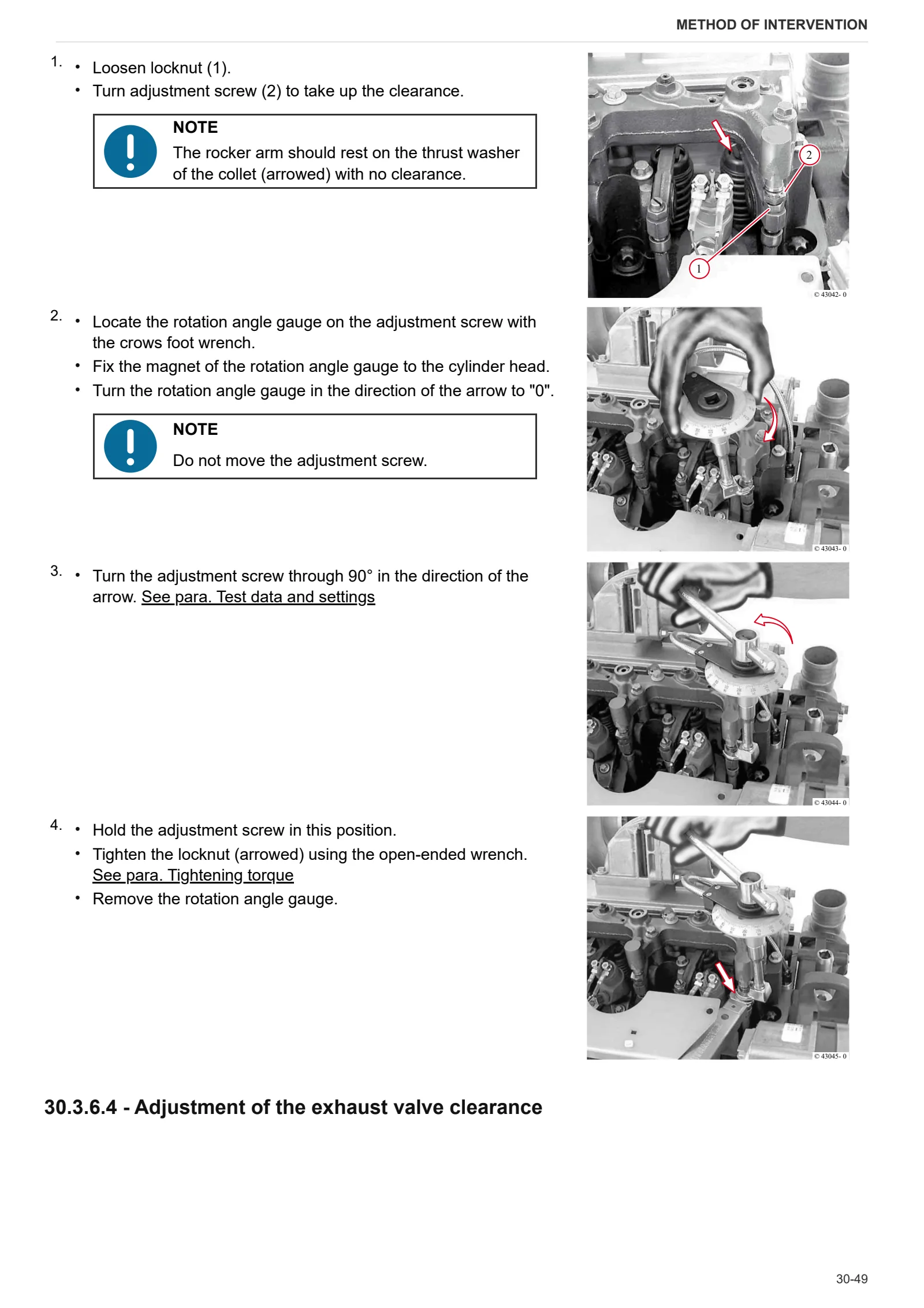
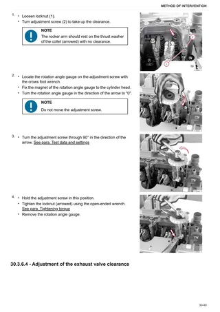
- Valve clearance adjustment (with the exhaust gas recirculation module absent or removed).
- Valve clearance adjustment (with the exhaust gas recirculation module installed).
- Removal and refitting of the rocker arms and pedestals
- Disassemble and complete the rocker and support, check
- Disassembly and assembly of the cylinder head
- Valve assembly and disassembly
- Valve check
- Check the valve guide
- Check the valve residual
- Check the endfloat of the crankshaft
- Check the crankshaft
- Replace the crankshaft O-ring (flywheel end)
- Replacing the crankshaft O-ring (opposite end to flywheel)
- Check the connecting rod drum
- Assembly and disassembly of the crankshaft
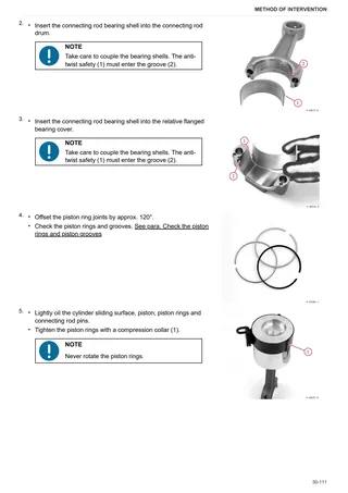
- Disassembly and assembly of the piston and connecting rod drum
- Check the piston
- Check the piston rings and piston grooves
- Assembly and disassembly of piston cooling nozzles
- Removal and refitting of the crankcase breather
- Cylinder liner check
- Fitting and removing the cylinder sleeve
- Check the protrusion of the cylinder liner
- Removal and refitting of the front cover (opposite end to flywheel)
- Disassembly and assembly of the connector box
- Disassembly and assembly of the gear case cover
- Assembly and disassembly of the camshaft
- Check the camshaft
- Removal and refitting of the turbocharger
- Removal and refitting of the charge air duct
- Fitting and removing the exhaust gas recirculation module
- Removing and fitting the fuel pump (driven by toothed belt)
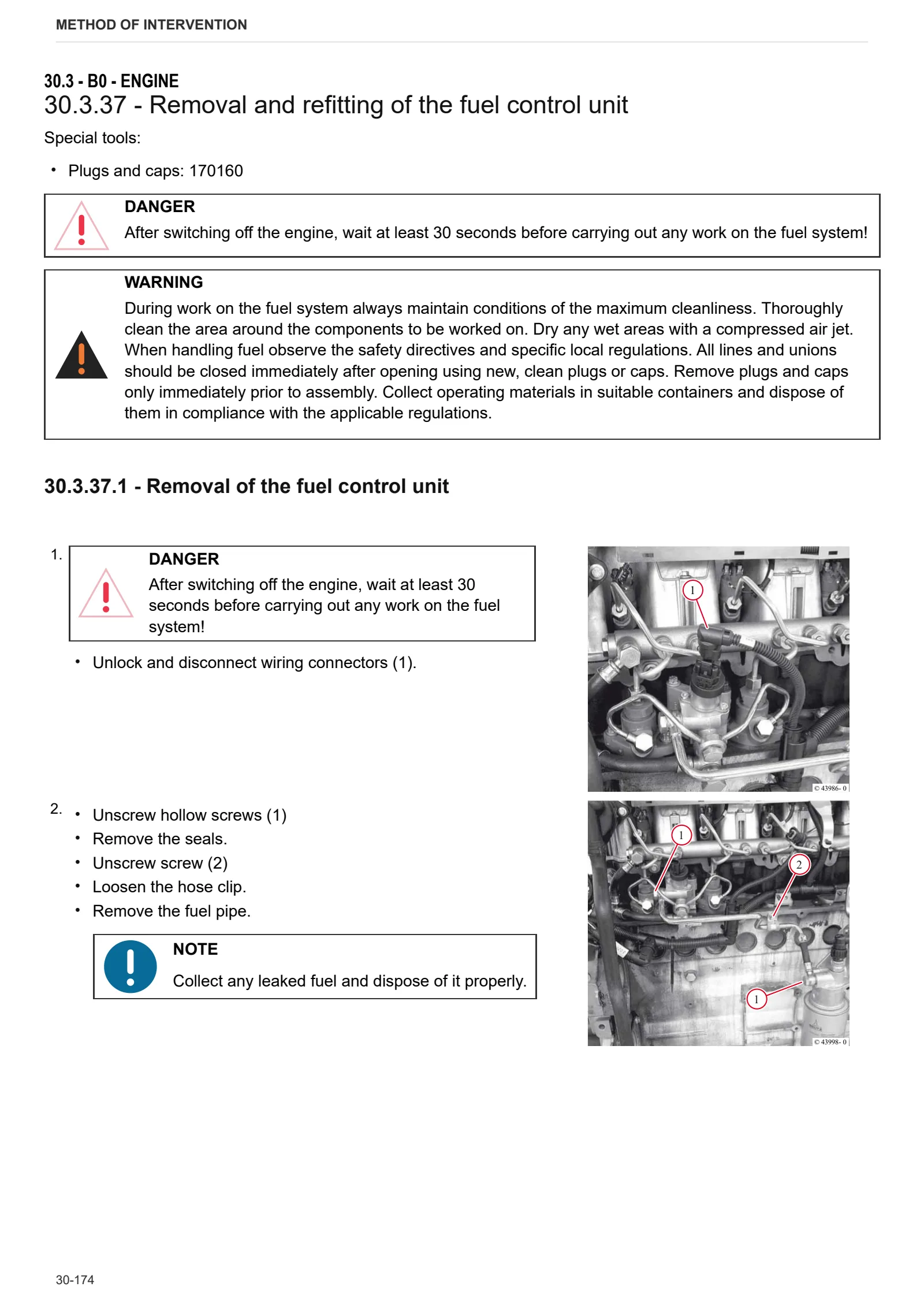
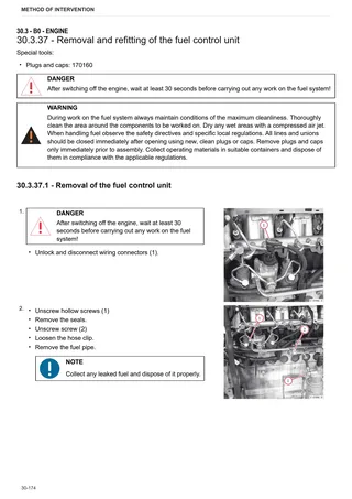
- Removal and refitting of the fuel control unit
- Removal and refitting of the high-pressure pump (installation position A)
- Removal and refitting of the high-pressure pump (installation position B)
- Removal and refitting of the common rail
- Removal and refitting of the injectors
- Removal and refitting of the pressure cut-off valve
- Removal and refitting of the fuel pressure sensor
- Disassembly and assembly of the gear case cover
- Removal and refitting of the oil sump pan.
- Removal and refitting of the oil cooler
- Disassembly and assembly of the oil radiator housing
- Removal and refitting of the oil pressure switch
- Fitting and removing the fuel pressure regulator valve
- Removing and fitting the coolant pump (driven by toothed belt)
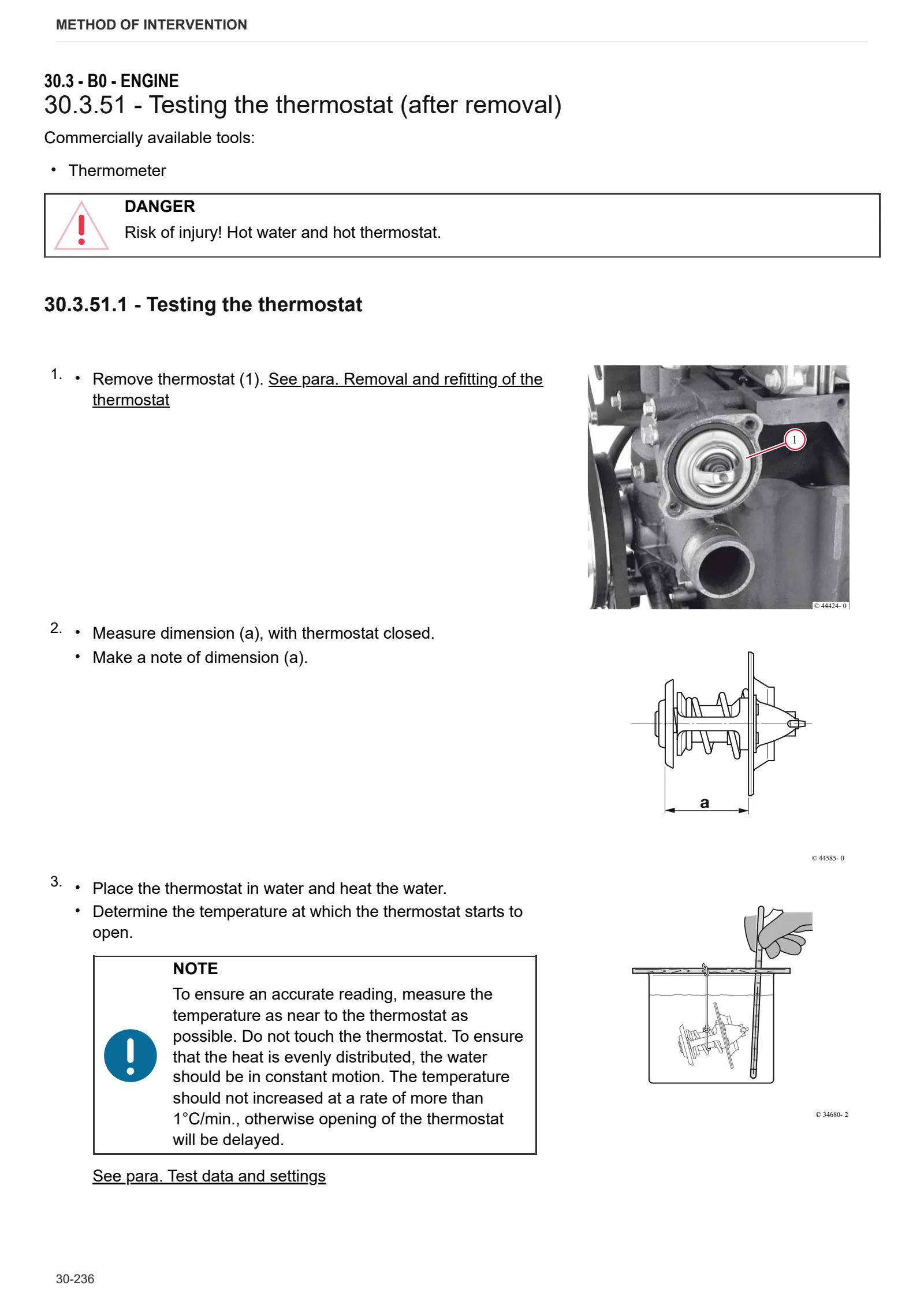
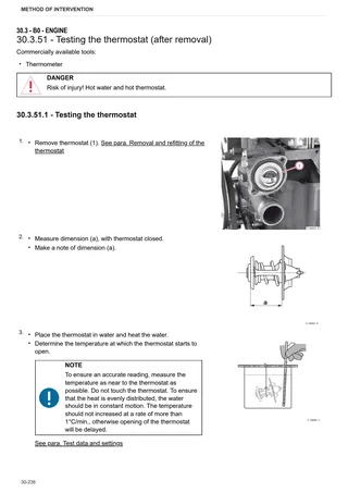
- Testing the thermostat (after removal)
- Removal and refitting of the thermostat
- Fitting and removing the thermostat housing
- Removing and refitting the torsional vibration damper (toothed belt drive)
- Removing and fitting the V-belt, V-belt pulley
- Removal and refitting of the flywheel
C0 – Engine accessories
- Disassembly and assembly of the speed indicator (crankshaft)
- Removal and refitting of the camshaft speed sensor
- Removal and refitting of the exhaust manifold
- Fitting and removing the solenoid valve (exhaust gas recovery module)
- Removal and refitting of the fuel filter head.
- Removal and refitting of the rail pressure sensor
- Assembly and disassembly of the temperature sender
- Removal and refitting of the engine wiring loom
- Removal and refitting of the alternator (with drivebelt)
- Disassembly and assembly of the starter
- Removal and refitting of the supply air pressure/temperature sender
Wiring diagrams
Introduction
- Introduction
- Basic electronics for mechanics (1/2)
- Basic electronics for mechanics (2/2)
- Electrical and electronic components (1/2)
- Electrical and electronic components (2/2)
Wiring harnesses
- 0421.4895 – Engine wiring