
Document overview
Workshop Manual for LAMBORGHINI Strike C 115 → ZKDEJ51500TL10001 from the STRIKE C (FARMOTION STAGE 3B) family. Digital PDF in English with 686 pages.
The corresponding English table of contents contains 35 sections and 292 individual topics.
Main sections included
- Introduction
- Technical characteristics
- Calibrations and electronic diagnosis
- Method of intervention
- Wiring diagrams
- Service Info
Document details
- Brand: LAMBORGHINI
- Family: STRIKE C (FARMOTION STAGE 3B)
- Model: Strike C 115
- Starting serial number: ZKDEJ51500TL10001
- Document type: Workshop Manual
- Language: English
- Pages: 686
- File size: 270.78 MiB
- Format: Digital PDF download
Compatibility
Before purchasing, verify that your machine model and reference code match LAMBORGHINI Strike C 115 → ZKDEJ51500TL10001.
Complete table of contents
Introduction
- Introduction
- Tightening torques
- Pump tightening torques
- Tightening torques for nuts and bolts of electrical connections
- Solenoid valves and cartridge valves
- Installation of quick couplers
Technical characteristics
Engine
- Technical data: cylinder block
- Technical data: crankshaft
- Technical data: pistons – piston rings
- Technical data: rockers
- Camshaft technical data
- Technical data: timing system gears
- Technical data: counter-rotating masses
- Technical data and dimensions: valves – valve springs
- Technical data and dimensions: heads – valve guides – valve seats
- Technical data, rockers – tappets
- Automatic tensioner
Engine accessories
- Starter motor
- Compensation tank
- Exhaust gas recirculation valve (EGR)
- Manual fuel pump
- Heater
- Fuel filter
- Fuel pre-filter
- Air filter
- Coolant radiator
- Intercooler
- Fuel radiator
- Gearbox oil radiator
- Viscostatic fan
- Exhaust silencer – Catalytic converter (DOC)
- Fuel tanks
Transmission
- Clutch
- Transmission
- Transmission diagram
- Rear power take off
- Hydraulic rear PTO clutch
- Rear power take off
Rear axle
- Rear axle
- Rear brakes
Hydraulic system
- Transmission hydraulic circuit
- Auxiliary hydraulic circuit, base version
- Auxiliary hydraulic circuit, optional version
- Hydraulic pumps
- Steering control valve
- Hydrostatic steering pump
- Auxiliary control valve
Electrical equipment
- Battery
- Alternator
- Alternator
- FARMotion engine sensors and components
Rear lift
- Rear lift
Crawler undercarriage
- Steering clutch
Ballast – Towing hitches
- Rear drawbar
- Ballasting
Calibrations and electronic diagnosis
Diagnostic instrument
- ECUs
- D-Tech and diagnostic ports
- D-TECH App
Commissioning and calibrating the tractor
- Commissioning procedure (EOL)
- ECU Reset
- Set vehicle model
ECU alarms
- SDF Severity of alarms
- ECU ALARMS
Software management
- ECUs firmware update
- Download Dataset FARMotion & Flash ECU
Method of intervention
B0 – Engine
- Preliminary operations before removing engine from vehicle
- Complete engine
- Engine- separation from the transmission
- Cylinder sleeves
- Engine-transmission mating flange
- Crankshaft pulley and tone wheel
- Crankshaft pulley
- Rear flange
- Ancillary utility belt
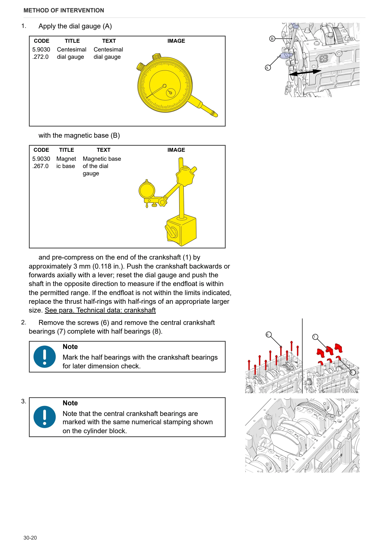
- Crankshaft
- Installing automatic belt tensioner
- Disassembling pistons and connecting rods
- Front timing cover
- Pushrods
- Intermediate gear and timing
- Power take off drive
- Counter-rotating masses
- Overhauling counter-rotating masses
- Cylinder head covers
- Cylinder heads
- Disassembling the cylinder heads
- Blow-by oil vapour recovery pipe
- Turbocharger oil pipes
- Blow-by filter
- Blow-by oil vapour pipe
- Cooling jets
- Oil filter
- Oil sump
- Adjusting oil pump gear backlash
- Oil pump
- Electro-injectors and common rail
- Oil heat exchanger
- Thermostat valve
- Aligning water pump and crankshaft pulleys
- EGR exhaust gas cooling pipes
- Coolant manifold
- Engine coolant pump
- Checking the thermostat valve
- EGR exhaust gas recirculation pipe
- EGR manifold
- EGR valve
- Disassembly of the EGR manifold
- Exhaust manifold
- Intake manifold
- Turbocharger
C0 – Engine accessories
- Coolant radiator
- Replacing the coolant
- Complete radiator-heat exchanger pack
- Compensation tank
- Engine air intake fan
- Intercooler
- Air filter
- Intercooler, oil and fuel exchangers
- Rigid air filter pipe
- High pressure fuel pump
- Fuel prefilter
- Fuel filter
- LH fuel tank float switch
- Right hand fuel tank
- Left hand fuel tank
- Manual fuel pump
- Fuel radiator
- Starter motor
- Mounting brackets
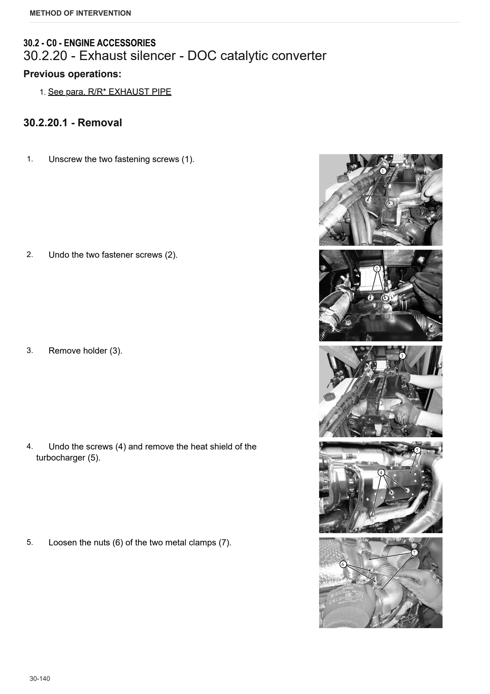
- Exhaust silencer – DOC catalytic converter
- Exhaust pipe
- Power take off gear backlash adjustment
- Bleeding the fuel circuit
D0 – Transmission
- Checking the transmission oil level
- Changing the transmission oil
- Engine clutch mount and thrust bearing
- Main clutch controls
- Connector housing
- Torsionally flexible coupling and flywheel
- Gearbox input shaft and the oil seal
- Gearbox input shaft shoe adjustment
- Reverse shuttle shaft
- Creeper or underdrive gear
- Primary shaft
- Complete transmission
- Internal gear controls
- Internal reverse shuttle controls
- Gear selector rod cover
- Internal creeper or underdrive controls
- Rear pinion (secondary shaft)
- Disassembling the secondary shaft (rear pinion)
- Adjustment of the bevel gear pair
- PTO hydraulic clutch
- Disassembling the rear PTO hydraulic clutch
- PTO hydraulic clutch adjustment
- Hydraulic pump drive
- Disassembling the power steering pump and ancillary pump carrier
- Adjusting power steering pump and ancillary pump carrier gear free play
- Rear PTO output shaft
- Rear PTO gears
E0 – Rear axle
- Draining oil from the rear crawler track final drive units
- Crawler track final drive unit cover
- Crawler track final drive unit pinion
- Disassembling the crawler track final drive unit
- Rear differential
- Disassembling the crawler track drive clutch
- Right hand crawler track final drive unit
- Left hand crawler track final drive unit
- Crawler track drive clutch
- Crawler track drive clutch – Clutch piston
- Disassembling the steering clutch piston
- Brake actuator piston
- Disassembling the brake actuator piston
- Adjusting the brake band
- Disassembling the brake drum and brake band
F0 – Front axle
- Front mount
G0 – Bodywork – Cab – Platform
- Engine hood and front hood panels
- Engine hood mount
- Lower hood guard
- Battery mount
- Platform
- Lift control instrument cluster
- Right hand mudguard
- Left hand mudguard
- Centre footboard
- Mat and footboards
- Instrument cluster
- Instrument cluster
- Seat
- Clutch pedal
- Brake pedals
- Procedure for brake pedals adjustment
- Steering pump levers
- Creeper or underdrive external controls
- Hydraulic control lever assembly
- Tool box
- Roll bar and mounts
H0 – Hydraulic system
- Auxiliary utilities hydraulic pump
- Disassembling the hydraulic ancillary pump
- Power steering pump
- Steering pumps
- Disassembling the steering pump
- Transmission oil filter
- Hydraulic circuit pressure holding valve
- Hydraulic circuit pressure holding valve disassembly
- Calibrating the hydraulic circuit pressure holding valve
- Transmission oil radiator
L0 – Electrical system
- Battery
- Alternator
- Engine wiring loom
- Electro-injector wiring loom
- Preheat relay
- Engine ECU
- Charge pressure and air temperature sensor
- Coolant temperature sensor
- Crankshaft speed sensor
- Camshaft timing sensor
- Engine oil pressure switch
- Engine oil temperature sensor
- Fuel pressure and temperature sensor
- Fuel pressure sensor
- Water in fuel sensor
R0 – Rear lift
- Complete rear lift
- Disassembling the lift and the relative components
- Lift control valve
- Disassembling the lift distributor
- Rear lift cylinders
- Replacing the lift cylinder gaskets
- 3-point linkage
T0 – Tracks
- Driving sprocket
- Front idler wheel
- Crawler track carrier roller
- Idler wheels
- Track tensioner cylinder
- Track tensioner spring
- Opening-closing the track chain
- Setting track chain tension
- Complete undercarriage
- Track roller frame alignment
V0 – Ballast – towing hitches
- Drawbar
- Front ballast
Wiring diagrams
Components
- Engine control unit
- MLHP Control Unit
- Seat safety ECU
- A – Starting and charging
- B – Fuses
- C – Grounds
- D – Intermediate connections
- E – On-board instruments
- F – External lights (rotating beacon)
- H – Manual electrical controls (steering column stalk)
- I – Circuit breakers
- J – Relays
- K – Sensors and transmitters
- L – Electromagnets and solenoid valves
- M – Electrical/electronic devices, Flasher units and Timers
- N – Electric motors and actuators
- O – Resistors and rheostats
- P – Various services
- R – Diagnostics
Systems
- S001 – Engine governor
- S002 – Preheating
- S003 – Activation and charging
- S004 – Lights
- S005 – Work lights
- S006 – Power take off (PTO)
- S007 – CAN line and diagnostics
- S008 – Instrument panel
Wiring harnesses
- 0.011.7840.4 – Rotating beacon
- 0.021.1217.4 – Heater
- 0.023.1280.4/20 – Engine – 4 cylinder version
- 0.023.1282.4 – Injectors – 4 cylinder version
- 0.024.2826.4/10 – Alternator – preheat
- 0.028.1600.4 – Battery negative
- 0.028.1601.4 – Control unit power supply
- 0.028.1604.4/10 – Front – 4 cylinder version
- 0.028.1605.4 – Battery – 3 cylinder version power supply
- 0.028.1606.4 – Battery – 4 cylinder version power supply
- 0.028.1610.4/10 – Central wiring loom
- 0.028.1611.4 – Power supply for platform without cab
- 0.028.1612.4 – Power supply for platform with cab
- 0.028.1613.4/10 – Rear wiring loom
- 0.028.1614.4 – Cowl lights
- 0.028.1616.4 – Work lights H9
- 0.028.1617.4 – Led work lights
- 0.028.1618.4/10 – Cab roof lights control
- 0.028.1619.4/10 – work lights
- 0.028.1620.4/10 – Throttle pedal
Service Info
D0 – TRANSMISSION
- PTO collar breakage
- Underdrive ball bearing breakage
T0 – CRAWLER TRACKS
- SERVICE NEWS – Front crosspiece p.n. 0.029.4843.2 – Improvement
- Oil leakage from crawler idler wheel