
Document overview
Workshop Manual for LAMBORGHINI SPARK 175 VRT → WSXFS50200LL50001 from the SPARK VRT (STAGE 5) family. Digital PDF in English with 2,500 pages.
The corresponding English table of contents contains 47 sections and 971 individual topics.
Main sections included
- Introduction
- Safety
- Technical characteristics
- Calibrations and electronic diagnosis
- Method of intervention
- Wiring diagrams
- Service Info
Document details
- Brand: LAMBORGHINI
- Family: SPARK VRT (STAGE 5)
- Model: SPARK 175 VRT
- Starting serial number: WSXFS50200LL50001
- Document type: Workshop Manual
- Language: English
- Pages: 2,500
- File size: 693.44 MiB
- Format: Digital PDF download
Compatibility
Before purchasing, verify that your machine model and reference code match LAMBORGHINI SPARK 175 VRT → WSXFS50200LL50001.
Complete table of contents
Introduction
- Tightening torques
- Pump tightening torques
- Installation of solenoid valves and cartridge valves
- Installation of quick couplers
- Units of measurement and conversion factors
Safety
Preface
- Important notes concerning safety
Important safety information
- Recognising hazards
- Indications for persons in contact with the tractor
Safety rules
- Risks during tractor preparation
- Risks during maintenance
- Work on machine systems
- Special disassembly/assembly/inspection procedures
Safety pictograms
- Replacing safety pictograms
Environmental risks
- Hazards associated with the operating environment
Technical characteristics
Engine
- Technical data – Pressure/temperature transmitter
- Technical data – Pressure transducer
- Pressure transducer
- Technical data – Pressure transducer
- Pressure sensor
- Technical data – Pressure transducer
- Pressure transducer
- Technical data – Pressure sensor
- Technical data – Temperature transmitter
- Technical data – Temperature transmitter
- Technical data – Temperature transmitter
- Temperature sender
- Technical data – Temperature transmitter
- Technical data – Temperature transmitter
- Technical data – Speed indicator
- Technical data – Speed indicator
- Technical data – Speed indicator
- technical specifications – NOx sensor (24 V)
- technical specifications – NOx sensor (12 V)
- Pressure transducer (exhaust gas backpressure) – (B60)
- Pressure transducer (ahead of SCR catalytic converter) – (B88)
- Differential pressure transducer (diesel particulate filter) – (B61)
- Differential pressure transducer (diesel particulate filter) – (B58)
- Pressure sensor (Rail) – (B49)
- Pressure transducer (lubricant oil) – (B6) / (fuel) – (B51)
- Pressure transducer (ahead of SCR catalytic converter) – (B88)
- Pressure transducer
- Pressure transducer
- Pressure/temperature sender (engine intake air) – (B48)
- Pressure/temperature sender (engine intake air) – (B48)
- Temperature sender (exhaust gas recirculation) – (B64)
- Temperature sender (intake air, ambient air) – (B74)
- Temperature sender (ahead of and after diesel oxidation catalyst) – (B65)
- Temperature sender (ahead of and after diesel oxidation catalyst) – (B65)
- Temperature sender (ahead of SCR catalytic converter) – (B78)
- Temperature sender (ahead of SCR catalytic converter) – (B78)
- Speed sensor (crankshaft) – (B40.2)
- Speed sensor (camshaft) – (B40.1) / (crankshaft) – (B40.2)
- Speed sensor (camshaft) – (B40.1)
- NOx sensor (SCR ahead of catalytic converter) – (B54)
- NOx sensor (SCR ahead of catalytic converter) – (B54)
- NOx sensor (SCR ahead of catalytic converter) – (B54)
- NOx sensor (SCR after catalytic converter) – (B56)
Transmission
- Transmission
- Rear PTO
Rear axle
- Rear axle
Front axle
- General information
- Special tools
- Safety information
- General characteristics
- Troubleshooting
Bodywork – Cab – Platform
- Brake master cylinders
- Air conditioning system
- Air conditioning system
- Air conditioning system – Diagnostics
- General introduction to the A/C system
- Compressor
- Condenser
- Filter-dryer
- Expansion valve
Hydraulic system
- Hydraulic System
- Ancillary utility distributor – 8-way version
- Ancillary utility distributor – 10-way version
- Variable displacement pump
- Variable displacement pump (63cc/rev)
- Gear pump for steering system (19 cc/rev)
- Gear pump for steering system (22.5 cc/rev)
- Priority valve
- Front suspension system – INTEGRAL accumulators
- Hydraulic power steering (OSPD)
- LS hydraulic power steering (OSPEDC)
- Hydraulic front axle suspension
- Servo-brake valve for front axle
- Servo-brake valve for front axle – Version with front brakes
- Braking system
- Master cylinder
- Rear lift distributor
- TRANSMISSION circuit, base version (“Mother Regulation”)
- TRANSMISSION circuit, optional version (“Mother Regulation”)
- TRANSMISSION circuit, optional version 2 (“Mother Regulation”)
- Agrosky circuit
- Ancillary utility distributor – Version for front lift
- Hydraulic trailer braking system – Italy version
- Hydraulic trailer braking system – Export version
- Hydraulic pump
- Load sensing valve, pressure cut-off valve
- Bistable valve block
- Suction line filter
- Delivery line filter
- Oil return filter
- Oil filter
- Pump filter
- LS variable displacement pump filter
- Logic block – brakes
- Compressor
- Pressure limiting valve
- Trailer air braking valve (2-way)
- Trailer air braking valve (1-way)
- Trailer air brake boost solenoid valve
- Trailer parking brake control solenoid valve
- Quick pressure release valve
Front PTO
- Front PTO
Calibrations and electronic diagnosis
- ECUs
Diagnostic tools
- D-Tech and diagnostic ports
- D-TECH App
Commissioning and calibrating the tractor
- Commissioning procedure (EOL)
- ECU Reset
- Set vehicle model
- Transmission Control Unit (TCU) initialization
- ECUs initialization
- Distributors configuration
- Maximum vehicle speed
- Tyre type
- Language
- Measurement unit
- Air brake
- Front Power Take-Off (PTO)
- Radar
- Automatic Air Conditioning
- iMonitor
- ISO 11786
- Isobus
- MMI (man machine interface)
- Agrosky
- Font Susp
- ASM (Automatic Steering Management)
- Front speed sensor
- Ext cylinders
- Oil pump displacement
- Stoll
- Engine brake
- Wet brake
- Pneumatic trailer brake
- Hydraulic trailer brake
- Distributors command calibration neutral
- Clutch pedal calibration
- Throttle pedal calibration
- Hand gas calibration
- Park brake parameter configuration
- Slope sensor calibration
- Water mix motor calibration
- Recirculation Motor calibration
- Draft sensor calibration
- Rear hitch position calibration
- Steering angle calibration
- Front hitch calibration
- Front suspension calibration
- Wheel angle sensor calibration
- PVED-CL Valve spool calibration
- Transmission calibration
- PTO calibration
- Front speed sensor calibration
ECU alarms
- SDF Severity of alarms
- ECU ALARMS
Software management
- Engine dataset upgrade
- ECUs firmware update
Method of intervention
- Tools for engine disassembly and reassembly
- Workshop tools for engine disassembly and reassembly (Lv.2)
- Workshop tools for disassembly and reassembly
B0 – Engine
- Engine
- Separating the engine from the transmission (1/2)
- Separating the engine from the transmission (2/2)
- Air conditioning compressor belt
- Water pump / alternator belt
- Disassembling and assembling alternator (poly-V-belt, level 1)
- Disassembling and assembling crankcase breather
- Replacing the crankshaft O-ring (opposite end to flywheel)
- Disassembling/assembling crankshaft wear sleeve (side opposite flywheel)
- Disassembling and assembling the front cover (fixing elements)
- Assembly and disassembly of piston cooling nozzles
- Assembly and disassembly of piston cooling nozzles
- Checking the camshaft bearing
- Removing and refitting crankshaft bearing cap
- Blanking elements
- Blanking elements
- Blanking elements
- Blanking elements
- Oil dipstick
- Oil dipstick
- Pipe (crankcase breather)
- Disassembling and assembling the lubricant oil sump (pressed steel sump)
- Removing and fitting lubricant oil sump (heavy version)
- Removing and fitting lubricant oil sump (heavy version)
- Removing and fitting lubricant oil sump (heavy version)
- Oil filler neck
- Disassembling and assembling the torsional vibration damper
- Disassembling and assembling the torsional vibration damper
- Disassembling and assembling the torsional vibration damper
- Disassembling and assembling the flywheel (fixing elements)
- Replacing the starter motor ring gear on the flywheel
- Removing and fitting the crankshaft
- Check the crankshaft
- Check the endfloat of the crankshaft
- Assembly and disassembly of the crankshaft bearing
- Check the crankshaft bearings
- Disassembly and reassembly of connecting rod shank
- Check the connecting rod shank
- Disassembling and assembling the piston
- Check the piston
- Check the piston
- Disassembling and assembling the piston rings
- Check the piston rings
- Check the piston rings
- Check the piston rings
- Compression test
- Disassembling and assembling the cylinder head cover
- Removing and fitting the cylinder head cover
- Disassembling and assembling the cylinder head (fasteners)
- Measuring piston protrusion
- Assembly and disassembly of the valves
- Checking valves, valve guides, valve springs and valve recess
- Replacing the injector bush
- Clean the injector bush
- Clean the injector bush seat
- Blanking elements (cylinder head)
- Eye-bolt for transporting (cylinder head)
- Eye-bolt for transporting (cylinder head)
- Replace the crankshaft O-ring (flywheel end)
- Disassembling and assembling the gearbox
- Assembly and disassembly of the camshaft
- Check the camshaft
- Checking and setting valve clearance (6 cylinder)
- Assembly and disassembly of the distribution valve
- Removing and refitting the valve timing system
- Disassembly and assembly of the control elements
- Disassembling and assembling the oil cooler
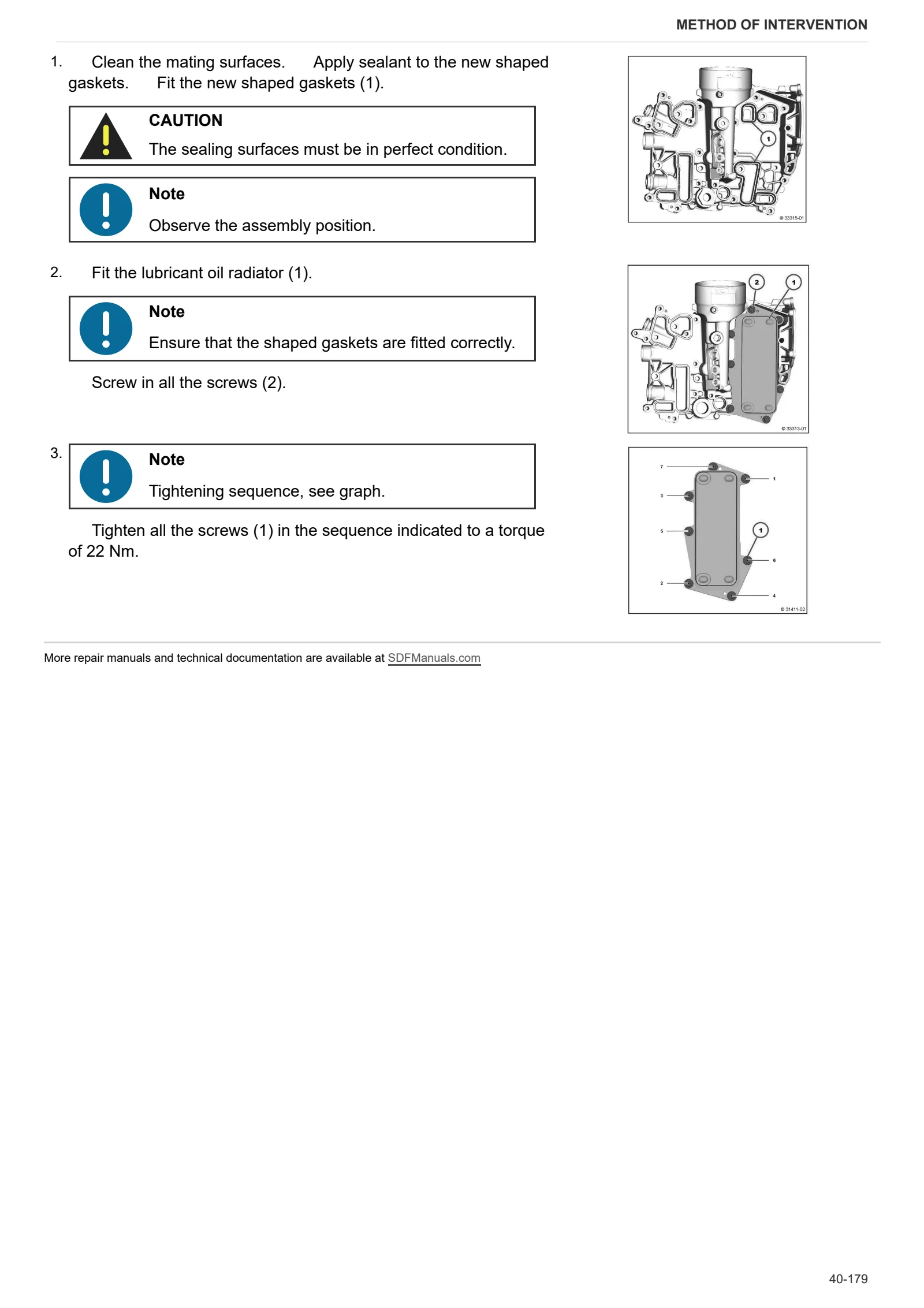
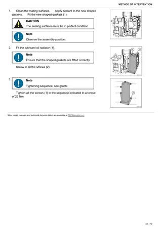
- Removing and fitting the lubricant oil radiator
- Removing and fitting the lubricant oil radiator
- Removing and fitting the lubricant oil radiator housing
- Disassembling and assembling the lubricant oil radiator (blanking elements)
- Removing and fitting the lubricant oil radiator housing (fastener elements)
- Blanking elements (lubricant oil cooler housing)
- Blanking elements (lubricant oil cooler housing)
- Coolant pipe (lubricant oil radiator housing – crankcase)
- Coolant pipe (Lubricant oil cooler – cylinder head)
- Disassembling and assembling the oil suction pipe
- Disassembly and assembly of the fuel control unit (fastening elements)
- Disassembly and completion of the fuel control unit
- Disassembling and completing assembly of the fuel control unit (2000 bar injection system)
- Disassembling and assembling the high pressure pump (fastener elements)
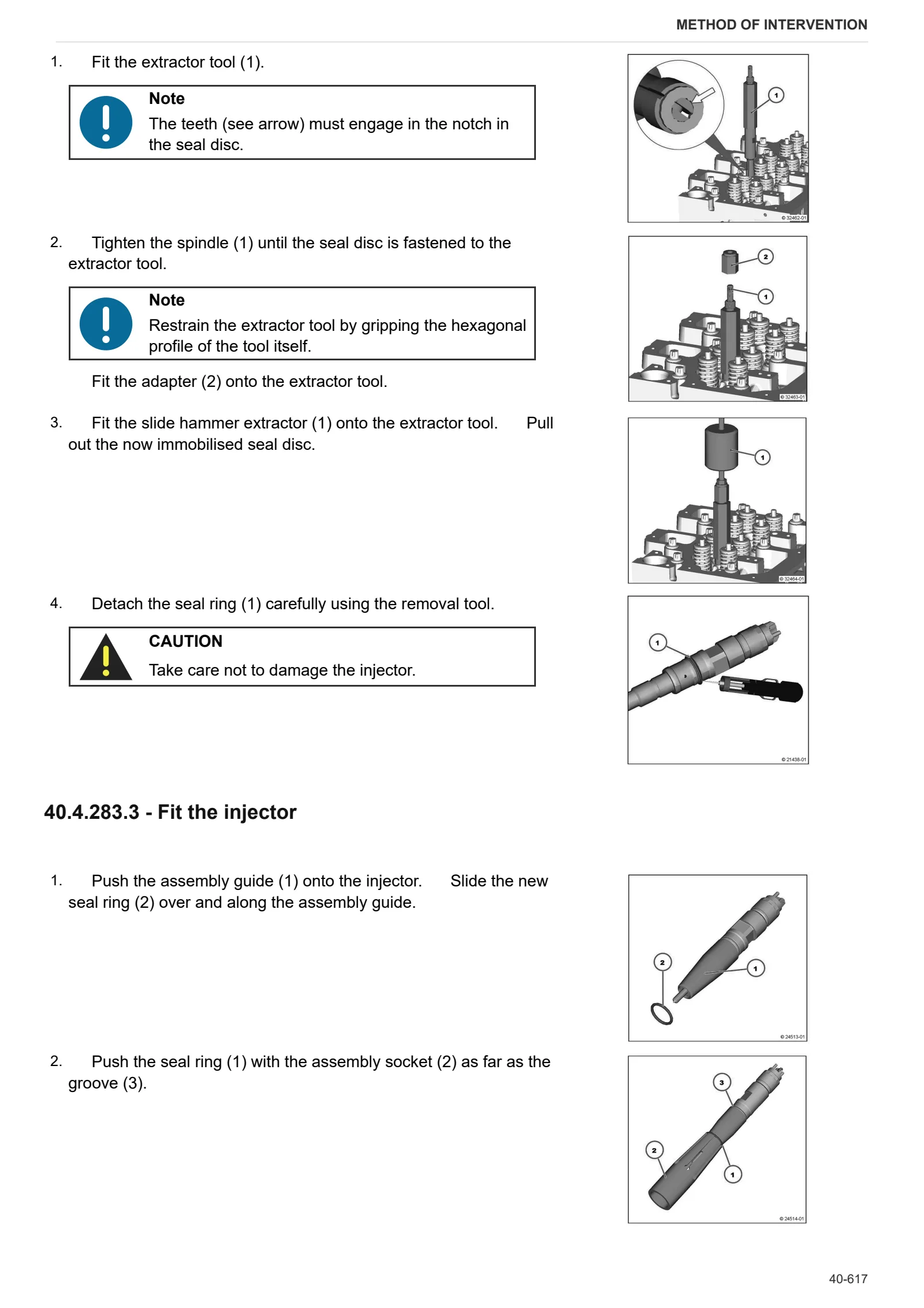
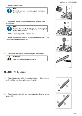
- Disassembling and assembling the injector (1600 bar injection system)
- Flexible hose connectors
- Disassembling and assembling the injector (1600 bar injection system)
- Connector plug (fuel delivery pump)
- Removing and refitting fuel lines (fuel delivery pump – pilot block)
- Disassembling and assembling the fuel line (fuel control block – high pressure pumps)
- Disassembling and assembling the rail (1600 bar injection system)
- Disassembling and assembling the rail (1600 bar injection system)
- Disassembling and assembling the rail (2000 bar injection system)
- Disassembling and assembling the pressure cut-off valve (rail)
- Disassembling and assembling the pressure cut-off valve (rail)
- Disassembly and assembly of the rail pressure sensor
- Disassembly and assembly of the rail pressure sensor
- Removing and refitting fuel lines (Rail, cylinder head, fuel control unit – fuel filter)
- Fuel pipes (Fuel pump, fuel filter, pilot lock)
- Fuel pipes (Rail, cylinder head, pilot lock- fuel filter)
- Vibration damper (installation position)
- Disassembling and assembling charge air pipe
- Disassembling and assembling charge air pipe
- Removing and fitting the coolant pump
- Disassembling and assembling coolant pipe (ribbed V-belt, level 1)
- Removing and fitting the coolant pump (fastening elements)
- Removing and refitting adapter (coolant pump – thermostat housing)
- Transmission components (coolant pump)
- V-belt pulley
- Assembling and disassembling the thermostat
- Assembling and disassembling the thermostat
- Disassembling and assembling the thermostat
- Check the thermostat (after removing)
- Check the thermostat (after removing)
- Removal and installation of the thermostat housing
- Removal and installation of the thermostat housing
- Removal and installation of the thermostat housing
- Disassembling and assembling the thermostat housing (fastener elements)
- Blanking elements (coolant pump – thermostat housing)
- Blanking elements (thermostat housing)
- Blanking elements (thermostat housing)
- Blanking elements (thermostat housing)
- Blanking elements (thermostat housing)
- Blanking elements (thermostat housing)
- Flexible hose fastening (Thermostat housing)
- Flexible hose connector (thermostat box)
- Connection (compensation line)
- Breather pipe (thermostat box – cooler)
- Pipes (AGR radiator cylinder head)
- Compensation line (thermostat box)
- Removing and fitting belt tensioner (ribbed V belt)
- Disassembly and refitting of the belt tensioner (ribbed V-belt, level 1)
- Disassembly and refitting of the belt tensioner (ribbed V-belt, level 1)
- Removal and assembly of the fan support
- Removal and assembly of the fan support
- Removal and assembly of the fan support
- Removal and assembly of the fan support
- Fastener elements (fan mount)
- Disassembling and assembling the exhaust manifold
- Disassembling and assembling the exhaust manifold
- Removal and installation of the exhaust pipe (auxiliaries)
- Disassembling and assembling the exhaust manifold
- Assembling and disassembling the console
- Disassembling and assembling the butterfly valve
- Disassembling and assembling the butterfly valves
- Disassembling and assembling the radiator
- Removing and fitting the exhaust gas recirculation (EGR) radiator
- Disassembling and assembling the regulator
- Disassembling and assembling the regulator
- Disassembling and assembling the Venturi pipe
- Disassembling and assembling the Venturi pipe
- Removing and fitting the pipes (cylinder head – radiator, radiator – cylinder head).
- Exhaust gas pipe (Venturi tubes – mixing tubes)
- Pipe (exhaust pipe – pressure transducer)
- Pipe (exhaust pipe – pressure transducer)
- Disassembling and assembling the turbocharger
- Disassembling and assembling the turbocharger
- Disassembling and assembling the turbocharger
- Disassembling and assembling the lubricating oil pipe (exhaust gas turbocharger)
- Disassembling and assembling the lubricating oil pipe (exhaust gas turbocharger)
- Removing and refitting the lubricant oil return pipe – (upper section) – (turbocharger)
- Removing and refitting the lubricant oil return pipe – (upper section) – (turbocharger)
- Disassembling and assembling the lubricating oil return pipe (turbocharger)
- Removing and refitting the lubricant oil return pipe – (lower section) – (turbocharger)
- Removing and refitting the lubricant oil return pipe – (lower section) – (turbocharger)
- Removing and refitting the lubricant oil return pipe – (lower section) – (turbocharger)
- Disassembling and assembling alternator (poly-V-belt, level 1)
- Disassembling and assembling alternator (poly-V-belt, level 1)
- Removing and fitting the V belt pulley/poly-V belt pulley (alternator)
- Disassembling and assembling the console (ribbed V-belt, level 1)
- Disassembling and assembling the console (ribbed V-belt, level 1)
- Disassembling and assembling the console (ribbed V-belt, level 1)
- Disassembling and assembling the console (ribbed V-belt, level 1)
- Fitting and removing the rotation device (PTOC)
- Fitting and removing the rotation device
- Disassembling and assembling the connector housing
- Cover (connector casing)
- Cover (connector casing)
- Cover (connector casing)
- Disassembling and assembling the heater
- Disassembling and assembling the heater
- Disassembling and assembling the heater
- Removing and fitting the charge air elbow pipe
- Disassembling and assembling the mixer pipe
- Disassembling and assembling the mixer pipe
- Disassembling and assembling the butterfly valve
- Disassembling and assembling the butterfly valve
- Disassembly and assembly of the flange
- Removing and refitting the diesel particulate filter
- Removing and fitting the diesel particulate filter (9.5 ” axial and radial system – removed)
- Disassembling and assembling the NOx sensor
- Pressure transducer (exhaust back-pressure).
- Fitting the SCR (Selective Catalytic Reduction) dosing unit
- Cleaning the SCR delivery pump (Selective Catalytic Reduction)
- Cleaning/Checking SCR (Selective Catalytic Reduction) metering unit
- Cleaning the SCR (Selective Catalytic Reduction) pipe (delivery pump – metering unit)
- Blanking elements (diesel oxidation catalytic converter/diesel particulate filter, SCR catalytic converter)
- Cover guard (Differential pressure transducer)
- Mount (Exhaust after-treatment system 9.5″)
- SCR (Selective Catalytic Reduction) urea solenoid valve
- SCR delivery pump (Selective Catalytic Reduction)
- Outlet module particulate filter
- Mixer pipe (threaded connection) SCR (Selective Catalytic Reduction)
- Mixer pipe (fastening element) SCR (Selective Catalytic Reduction)
- Blanking elements (crankcase, PTO-A)
- Closing elements (Power Take-Off PTO-B)
- Closing elements (Power Take-Off PTO-B)
- Blanking elements (gearbox, PTO-C)
- Blanking elements (gearbox, PTO-C)
- V-belt pulley
- Disassembly and assembly of fan mount
- Removing and fitting the belt tensioner (ribbed V-belt, level 2)
- Checking crankcase pressure
- Removing and fitting the crankcase breather
- Disassembling and assembling crankcase breather
- Removing and fitting the crankcase breather
- Removing and fitting the crankcase breather
- Removing and fitting the crankcase breather
- Removing and fitting the crankcase breather
- Blanking tools (crankcase, electronic engine governor)
- Fastener elements (crankcase)
- Blanking tool (crankcase)
- Mount (crankcase breather)
- Support (Assembly foot, opposite side to flywheel)
- Fitting and removing the rotation device (PTOC power take off)
- Blanking elements (crankcase, PTO-A)
- Blanking elements (crankcase, PTO-A)
- Fastener elements (gearbox, PTOC power take off)
- Fastener elements (gearbox, PTOC power take off)
- Fastener elements (PTO-B power take off)
- Blanking elements (PTO-B)
- Blanking elements (PTO-B)
- Cover (connector casing)
- Replacing crankshaft seal ring (side opposite flywheel).
- Fitting and removing the crankshaft sleeve (side opposite flywheel)
- Checking the camshaft bearing
- Removing and fitting and the crankshaft bearing cap
- Removing and fitting the V belt pulley/poly-V belt pulley
- Removing and fitting the torsional vibration damper
- Disassembling and assembling the torsional vibration damper
- Removing and fitting the torsional vibration damper
- Disassembling and assembling the flywheel (fixing elements)
- Replacing the starter motor ring gear of the flywheel
- Fitting and removing the crankshaft bearings
- Checking the crankshaft
- Check the endfloat of the crankshaft
- Fitting and removing the crankshaft bearings
- Checking the crankshaft bearings
- Removing and fitting the sensor wheel
- Replacing the crankshaft seal ring (flywheel side)
- Removing and fitting the connecting rod shank
- Checking the connecting rod shank
- Disassembling and assembling the piston rings
- Check the piston rings
- Measuring piston protrusion
- Disassembling and assembling the gearbox
- Checking the camshaft
- Checking compression
- Removing and fitting the cylinder head cover
- Removing and fitting the cylinder head cover
- Disassembling and assembling the cylinder head (fasteners)
- Removing and fitting the valves
- Transport eye-bolt (cylinder head)
- Transport eye-bolt (cylinder head)
- Transport eye-bolt (cylinder head)
- Oil dipstick
- Oil dipstick
- Removing and fitting the lubricant oil sump (pressed steel lubricant oil sump)
- Disassembling and assembling the lubricant oil sump (pressed steel sump)
- Removing and fitting lubricant oil cooler
- Removing and fitting lubricant oil cooler (fastener elements)
- Removing and fitting the lubricant oil cooler
- Removing and fitting lubricant oil cooler
- Removing and fitting the lubricant oil cooler housing
- Removing and fitting the lubricant oil cooler housing (fastener elements)
- Blanking elements (lubricant oil cooler housing)
- Fastener elements (lubricant oil cooler housing)
- Fastener elements (lubricant oil cooler housing)
- Coolant pipe (lubricant oil cooler – cylinder head)
- Removing and fitting the oil suction pipe
- Cleaning the injector bush
- Cleaning the injector bush seat
- Disassembly and assembly of the fuel control unit (fastening elements)
- Disassembling and completing assembly of the fuel control unit (2000 bar injection system)
- Disassembling and assembling the high pressure pump (fastener elements)
- Removing and fitting the injector (1600 bar injection system)
- Removing and fitting the injector (1600 bar injection system)
- Removing and fitting the injector (2000 bar injection system)
- Removing and fitting the fuel filter console (bowl)
- Removing and fitting the fuel pump (fastener elements)
- Fuel filter
- Fuel filter
- Fuel filter
- Fuel filter
- Removing and fitting the fuel lines (fuel pump – pilot block)
- Removing and fitting the fuel line (pilot block high pressure pumps)
- Removing and fitting the rail (1600 bar injection system)
- Removing and fitting the rail (1600 bar injection system)
- Fitting and removing the pressure limiting valve (Rail)
- Fitting and removing the pressure limiting valve (Rail)
- Fitting and removing the rail pressure sensor
- Fuel pipe (fuel filter – pilot block)
- Fuel pipe (rail, cylinder head, pilot block)
- Fuel pipe (fuel delivery pump, fuel filter, pilot block)
- Vibration damper (assembly position)
- Pressure transducer (exhaust gas backpressure)
- Pressure transducer (exhaust gas backpressure)
- Removing and fitting the coolant pump
- Removing and fitting the coolant pump (V-belt, level 1)
- Removing and fitting the coolant pump
- Removing and fitting the coolant pump
- Removing and fitting the thermostat
- Removing and fitting the thermostat
- Check the thermostat (after removing)
- Removing and fitting the thermostat housing (fastener elements)
- Fastener elements (coolant pump thermostat housing)
- Fastener elements (thermostat housing)
- Blanking elements (thermostat housing)
- Fastener elements (thermostat housing)
- Fastener elements (thermostat housing)
- Fitting (compensation line)
- Pipes (EGR radiator cylinder head)
- Pipes (EGR radiator cylinder head)
- Removing and fitting the boost air hose
- Removing and fitting the boost air hose
- Removing and fitting the exhaust pipe (auxiliary)
- Removing and fitting the exhaust pipe.
- Removing and fitting the radiator
- Removing and fitting the temperature sender
- Mount (exhaust gas recirculation radiator)
- Connector cable (intake air)
- Removing and refitting the diesel particulate filter
- Removing and fitting the turbocharger
- Removing and fitting the turbocharger
- Removing and fitting the turbocharger
- Removing and fitting the lubricant oil return pipe (upper section) (Turbocharger)
- Removing and fitting the lubricant oil return pipe (upper section) (Turbocharger)
- Removing and fitting the lubricant oil return pipe (upper section) (Turbocharger)
- Removing and fitting the lubricant oil return pipe (lower section) (Turbocharger)
- Removing and fitting the lubricant oil return pipe (lower section) (Turbocharger)
- Removing and fitting the lubricant oil return pipe (lower section) (Turbocharger)
- Disassembling and assembling the heater
- Disassembling and assembling alternator (poly-V-belt, level 1)
- Disassembling and assembling the crankshaft speed sensor (fasteners)
C0 – Engine accessories
- Engine coolant replacement
- AdBlue Connection Backflow – Inlet pipes
- AdBlue tank
- Intercooler, gearbox oil and fuel exchangers and condenser
- AdBlue pump module
- AdBlue 2 way solenoid valve
- Draining the fuel tanks
- Main fuel tank
- Auxiliary tank
- Auxiliary fuel tank mount
- Fuel prefilter
- Air compressor
- Air compressor disassembly
- Starter motor
- Catalytic exhaust silencer
- DOC (diesel oxidation catalyst) catalytic converter
- Complete radiator pack
- Cooler
- Compensation tank
- Fan
- Air filter cartridge
- Air filter container
- Removing and fitting the fuel filter head
- Disassembling and assembling the fuel delivery pump (fastener elements)
- Fuel filter
- Manual fuel pump
- Filter holder
- Assembly of the pressure transducer (fuel pressure)
- Disassembly and refitting of the intake air pressure/temperature sender
- Blanking elements (mixer pipe, intake air)
- Shield plate (exhaust gas back-pressure sensor)
- Turbocharger shield plate
- Support plate (exhaust gas back-pressure relay – sensor)
- Support (shield plate)
- Pressure transducer (exhaust back-pressure).
- Pressure transducer (exhaust back-pressure).
- Connector manifold (intake air)
- Connector manifold (intake air)
- Intake manifold (exhaust gas turbocharger)
- Removing and fitting the fan mount (fastener elements)
- Removing and fitting the fan mount (fastener elements)
- Removing and fitting the temperature sender
- Removing and fitting the pressure transducer
- Mount (radiator – exhaust gas recirculation)
- Mount (radiator – exhaust gas recirculation)
- Pressure transducer/Duct (exhaust gas back-pressure).
- Pressure transducer/Duct (exhaust gas back-pressure).
- Disassembling and assembling the pressure transducer (exhaust back-pressure)
- Connection (Starter)
- Connection (Starter)
- Shield plate (starter)
- Alternator
- Starter (fasteners)
- Mount (Assembly foot, side opposite of the flywheel)
- Mount (assembly foot, side opposite of the flywheel)
- Mount (assembly foot, flywheel side)
- Disassembling and assembling the crankshaft speed sensor (fastener elements)
- Disassembling and assembling the crankshaft speed sensor (fasteners)
- Disassembling and assembling the crankshaft speed sensor (fasteners)
- Disassembling and assembling the camshaft speed sensor (ancillaries)
- Disassembly and refitting of the intake air pressure/temperature sender
- Fastener elements (wiring bundle)
- Fastener elements (wiring bundle)
- Fastener elements (wiring bundle)
- Support plate (on the charge air pipe)
- Support (wiring harness)
- Temperature sender (coolant)
- Fitting the pressure transducer (fuel pressure / lubricant oil pressure)
- Relay (heater, thermo-starter, glow plugs)
- Connector cable (relay – alternator)
- Connector cable (relay – heater)
- Protective cap (relay)
- Heater (connector line)
- Check the seal of the cooling system
- Differential pressure sender (diesel particulate filter)
- Differential pressure sender (diesel particulate filter)
- Temperature sender (upstream of the SCR catalytic converter)
- Temperature sender (ahead of and after diesel oxidation catalytic converter)
- Temperature sender (exhaust gas)
- Temperature sender (inlet air and ambient air temperature)
- V-Band clamp.
- VBand clamp (4″ exhaust pipe)
- VBand clamp (turbocharger)
- Mount (exhaust gas back-pressure sensor)
- Assembly of the pressure transducer (fuel pressure)
- Check the seal of the cooling system
- Mount (fasteners)
- Mounting plate (on boost air hose)
- Cable harness (fastener elements)
- Flushing the SCR (Selective Catalytic Reduction) delivery pump
- Flushing/Checking SCR (Selective Catalytic Reduction) metering unit
- Flushing the SCR (Selective Catalytic Reduction) pipe (delivery pump – metering unit)
- Mount (exhaust backpressure sensor)
- Fitting (starter motor)
- Fitting (starter motor)
- Shield plate (starter motor)
- Removing and refitting the diesel particulate filter (module size 9.5″)
- Fastener elements (exhaust aftertreatment system) (NOx sensor, temperature sender, diesel particulate filter differential pressure sender)
- Mount (module size 9.5”)
- VBand clamp (3″ exhaust pipe)
- Inlet module (module size 9.5″)
- Outlet module (module size 9.5″)
- Mixer pipe (threaded connection)
- Removing and fitting the V-belt pulley (version with locking cone)
- Alternator
- Alternator
- Removing and fitting the rotational speed sensor (crankshaft)
- Disassembly and refitting of the intake air pressure/temperature sender
- Fitting the pressure transducer (fuel pressure / lubricant oil pressure)
- Heater relay
- Disassembling and assembling the NOx sensor
- Assembling the SCR (Selective Catalytic Reduction) metering unit
- Differential pressure sender (diesel particulate filter)
- SCR (Selective Catalytic Reduction) solenoid valve
D0 – Transmission
- Changing the transmission oil
- Torsionally flexible coupling and flywheel
- Connector housing
- Separating the gearbox housing from the rear gearbox housing
- Removal of transmission
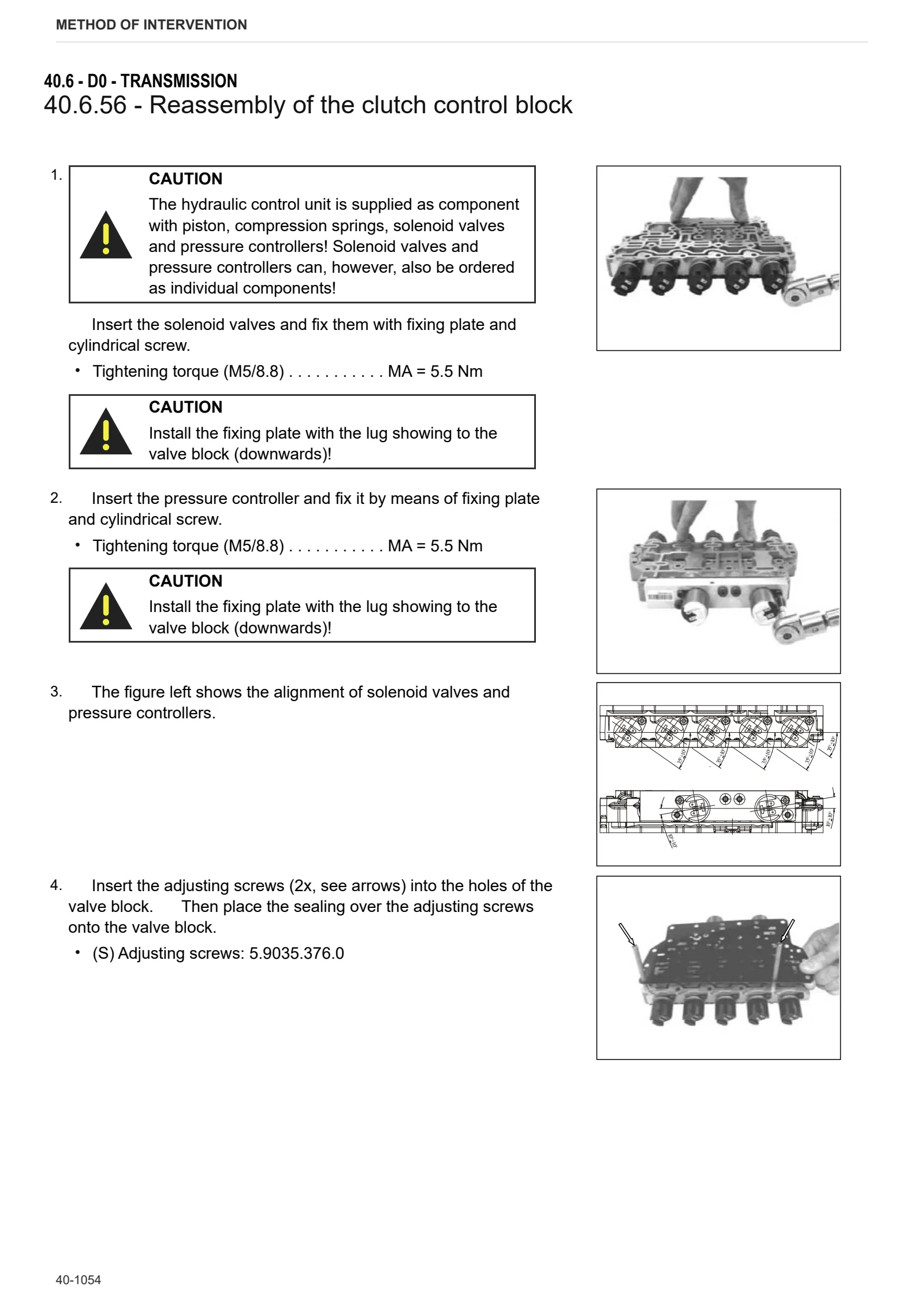
- Disassembly of the clutch control block
- Disassembly of the system control block
- Disassembly of the pump
- Separation of the transmission halves
- Disassembly of the intermediate housing
- Disassembly of the front wheel drive
- Disassembly of clutch KV/KR and double gear
- Disassembly of clutch KV
- Disassembly of clutch KR
- Disassembly of the output gear
- Disassembly of the input shaft (hydrostatic unit)
- Disassembly of the central shaft (clutch KV/KR)
- Disassembly of the intermediate gear
- Disassembly of the multi-disk brake (BG)
- Disassembly of the drum selector gear (planetary transmission)
- Disassembly of the ring gear P4/BG and clutch K3/K4
- Disassembly of planetary drive P4
- Disassembly of the central shaft
- Disassembly of clutch K1/K2
- Disassembly of planetary drive P3
- Disassembly of planetary drive P2
- Disassembly of planetary drive P1
- Disassembly of the hydrostatic unit
- Reassembly of the clutch housing
- Reassembly of the hydrostatic unit
- Reassembly of the drum selector gear (planetary transmission)
- Reassembly of planetary drive P1
- Reassembly of planetary drive P2
- Reassembly of planetary drive P3
- Reassembly of clutch K1/K2
- Reassembly of the central shaft
- Reassembly of planetary drive P4
- Reassembly of clutch K3/K4 and ring gear P4/BG
- Reassembly of the multi disk brake (BG)
- Reassembly of the intermediate housing
- Reassembly of the input shaft (hydrostatic unit)
- Reassembly of the intermediate gear
- Reassembly of the central shaft (clutch KV/KR)
- Reassembly of the output gear
- Reassembly of the pump
- Reassembly of clucth KV/KR
- Reassembly of clutch KV
- Reassembly of clutch KR
- Reassembly of the front wheel drive
- Joining of the preassembled transmission halves
- Setting of the axial play drum selector gear/quill shaft (KV/KR) – Axial play= 0.20 … 0.40 mm
- Setting of the axial play of the KV/KR bearing – Axial play= 0.00 … 0.08 mm
- Setting of the axial play of the double gear bearing – Axial play= 0.00 … 0.08 mm
- Setting of the axial play of the front wheel drive – Axial play= 0.025 … 0.1 mm
- Reassembly of the system control block
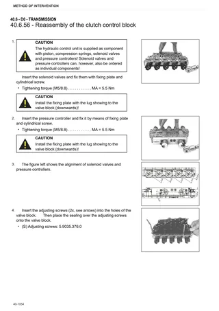
- Reassembly of the clutch control block
- Reassembly of the speed and inductive sensor
- Pump Drive flange
- Disassembly of the Pump Drive flange
- Adjusting bevel gear set ( … <- )
- Adjusting bevel gear set ( -> … )
- Removing the rear pinion
- PTO clutch
- Disassembling PTO control clutch
- Rear power take off unit
- Disassembling the rear power take off unit
- Adjustment of selector sleeve position
- Adjusting the handbrake device
E0 – Rear axle
- RH rear wheel carrier
- LH rear wheel carrier
- Disassembly of LH/RH rear axle
- Adjustment of rear half-shaft bearings
- Disassembly of the planet carrier
- Rear differential
- Disassembly of the rear differential
- Rear axle brake discs and braking assembly
- Renewal of brake seals
- Adjusting the EPB – Bowden assembly
- Rear brakes
F0 – Front axle
- Steering cylinder assembly
- 4WD shaft
- Planetary reduction gearbox unit
- Wheel hub assembly
- Beam assembly
- Carrier assembly
- Differential carrier assembly (Limited Slip)
- Differential carrier assembly (Wet Clutch)
- Differential assembly
- Pinion assembly
- Toe-in/steering angle
- Post-assembly tests
- Bevel gear set
- Wheel assembly
- Front carrier
G0 – Bodywork – Cab – Platform
- Empty and charge the air conditioning system
- Air conditioning compressor
- A.C. Electronic Control Unit replacement
- Condenser
- Front mudguards
- Main tank mount
- Battery mount
- Left hand cab access steps
- Right hand cab access steps
- Master cylinder
- Cab
- Engine hood
- Mat
- Under-seat mat
- Driver seat
- Passenger seat
- Left hand rear pillar cover
- Right hand rear pillar cover
- A/C unit
- Steering wheel
- Instrument cluster
- Right hand control console
- Left hand console
- Active carbon filter
- Cab roof panel trim
- Park brake control
- Rear power take off control levers
H0 – Hydraulic system
- Draining and filling the auxiliary utility oil tank
- Auxiliary utility oil tank
- Bleeding the braking circuit
- Power steering
- Power steering pump
- Front lift control valve
- Brake system accumulator
- Rear distributor unit
- Disassembly of the rear distributor unit (1/2)
- Disassembly of the rear distributor unit (2/2)
- Variable displacement L.S. pump
- Transmission L.S. hydraulic block
- Brake block
- Brake control valve
- Priority valve
- Resonator
- Oil delivery line filter
- Rear differential lock
- Transmission hydraulic plant heat exchanger
- Front auxiliary hydraulic distributor
- Front axle suspension solenoid valve block.
- Trailer air braking valve
- Air tanks
- Air braking system air filter
- Tightening the hydraulic power steering unit fastener screws
L0 – Electrical system
- Instrument cluster
- Radar
- Front lift position sensor
- Front suspension position sensor
- Inductive position sensor
- Pressure switch
- 35 Bar sensor
- Air filter clogged sensor
- Clutch pedal sensor
- Auxiliary utility oil tank pressure switch
- Auxiliary utility oil tank temperature sensor
- 63cc oil filter clogging pressure switch
- Rear lift position sensor
- Brake control switch
- Power steering delivery hydraulic system pressure switch
- Tightening torques for nuts and bolts of electrical connections
N0 – Front lift
- Front lift
R0 – Rear lift
- Lift cylinders
- Lift draft sensor
- Position sensor bushing
- 3-point linkage
S0 – Wheels
- Front Wheels
- Rear wheels
V0 – Ballast – towing hitches
- Tow hook sled
V1 – AFTERMARKET KITS
- Installation of the cab pillar filter frames kit (p.n. 9.AB386.91.0)
- Installation of the connector’s cover kit
Wiring diagrams
Components
- Location of ECUs
- Electronic Control Unit For Remote Controls
- Air Conditioning Control Unit
- Antenna Agrosky AGI4
- CTM/AM55 Control Unit
- Engine Control Unit – ECU
- TRANSMISSION CONTROL UNIT
- EPB – Control unit
- HLHP control unit (body)
- HLHP control unit (cab)
- Ad-Blue Control unit
- A – Engine start and charging
- B – Fuses
- C – Grounds
- D – Intermediate connections
- E – On-board instruments and visual and audible indicators
- F – External lights (rotating beacon)
- G – Interior lights
- H – Manual electrical controls (steering column stalk)
- I – Circuit breakers
- J – Relays
- K – Sensors and transmitters
- L – Electromagnets and solenoid valves
- M – Electrical/electronic devices, Flasher units and Timers
- N – Electric motors and actuators
- O – Resistors and rheostats
- P – Various services
- R – Diagnostics
Systems
- S002 – Starter
- S003 – Engine control
- S004 – Emissions control system
- S005 – Front lights
- S006 – Rear work lights
- S007 – Front work lights
- S008 – Sidelights and backlighting
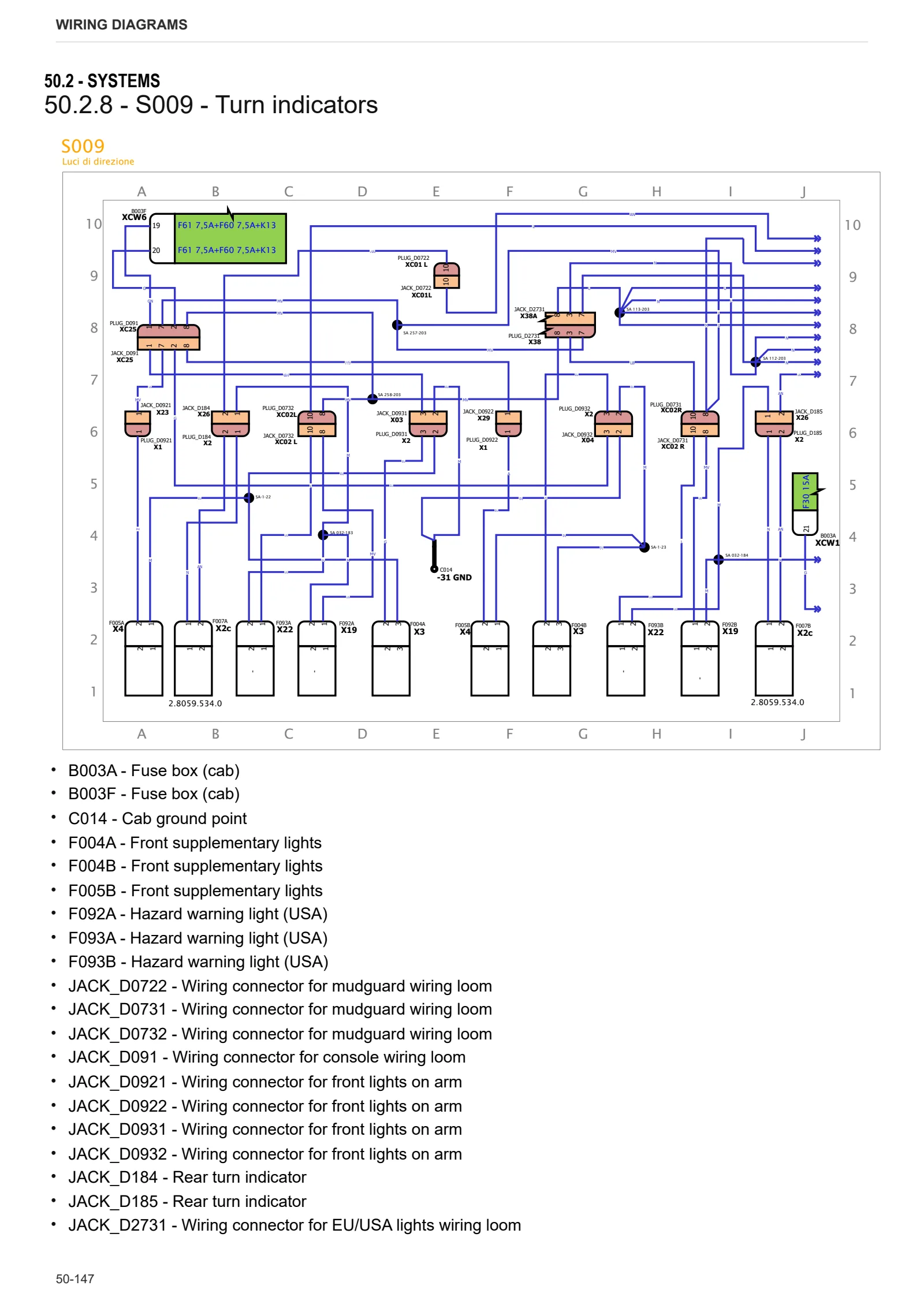
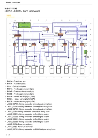
- S009 – Turn indicators
- S010 – Internal illumination
- S011 – Roof lights
- S012 – Defrost and wiper
- S013 – Horn
- S014 – Mirror adjustment
- S015 – Radio
- S016 – Power sockets and accessories
- S017 – Air conditioning
- S018 – Front lift
- S019 – Rear lift
- S020 – Braking system
- S021 – Trailer brake
- S022 – Transmission
- S024 – PTO
- S025 – Isobus
- S026 – AUX CAN line
- S027 – Vehicle CAN line
- S028 – Agrosky
- S029 – Instrument panel, work display
- S030 – Front axle
- S031 – Front loader
- S032 – Distributors
- S033 – Autoguidance CAN line
- S034 – Engine CAN line
- S035 – Distributor CAN line
- S037 – Serial CAN lines
Wiring harnesses
- 0.012.2018.4_20 – License plate light
- 0.014.1567.4_30 – Windscreen wiper motor wiring loom
- 0.016.8489.4A – Left hand engine brake
- 0.016.8489.4B – Right hand engine brake
- 0.017.0496.4_10A – H9 left hand lower front work lights
- 0.017.0496.4_10B – H9 right hand lower front work lights
- 0.017.0497.4_30A – H9 left hand lower rear work lights
- 0.017.0497.4_30B – H9 right hand lower rear work lights
- 0.017.8425.4/10 – Trailer socket, EU
- 0.017.8426.4 – Trailer socket, USA
- 0.017.9761.4_20 – Distributors 6_7
- 0.018.2800.4 – Hydraulic trailer braking
- 0.019.2379.4_20A – Front lights on left hand arm
- 0.019.2379.4_20A – Front lights on right hand arm
- 0.019.2380.4_50 – Hazard warning lights switch (USA)
- 0.019.2571.4_10 – ISO 11786
- 0.019.3659.4_30 – i-Monitor (Base version)
- 0.019.4559.4_10 – H9 rear work light (service)
- 0.019.4689.4/30 – H9 rear work lights on cab roof
- 0.019.4914.4_30 – LED rear work lights on cab roof
- 0.019.5311.4/10 – Automatic A/C system
- 0.019.9825.4_20 – Antenna – Inertial SRC40
- 0.019.9829.4_30 – Agrosky SR10 antenna
- 0.020.1009.4A – Front lights on left hand arm (USA)
- 0.020.1009.4B – Front lights on right hand arm (USA)
- 0.020.8862.4_30 – Roof
- 0.021.0490.4_10 – Trailer ABS
- 0.021.1028.4_10 – Agrosky adapter
- 0.021.3932.4_10 – ISOBUS module
- 0.021.5509.4 – Rear screen defrost adapter
- 0.021.8291.4A – LED left hand front work lights
- 0.021.8291.4B – LED right hand front work lights
- 0.021.8334.4A – LED left hand rear lights
- 0.021.8334.4B – LED right hand rear lights
- 0.023.0526.4_10 – Rear wiring loom, TTV7 MR
- 0.023.9007.4_30 – Front
- 0.023.9008.4_20 – Hood
- 0.023.9201.4_20 – Battery cables
- 0.023.9202.4/10 – Front axle steering sensor (Dana)
- 0.023.9204.4_10 – Electrohydraulic steering (Agrosky)
- 0.023.9205.4 – Electrohydraulic controls
- 0.023.9206.4 – Prewiring for external solenoid valve module
- 0.023.9207.4_10 – Cable adapter on front arm
- 0.023.9243.4_20 – Front ISOBUS socket
- 0.023.9244.4_20 – Rear ISOBUS socket
- 0.023.9246.4_10 – TECU wiring loom
- 0.023.9247.4/10 – Front loader
- 0.023.9248.4 – Viscostatic fan
- 0.023.9249.4 – Front loader module
- 0.023.9250.4_20A – LH rear mudguard
- 0.023.9250.4_20B – Right hand rear mudguard
- 0.023.9567.4_40 – Engine
- 0.023.9582.4_40 – LED front work lights on cab roof
- 0.023.9583.4_40 – H9 front work lights on cab roof
- 0.024.0765.4 – Rear screen defrost adapter
- 0.024.1909.4_10 – Engine (LRC)
- 0.024.3197.4_20 – Front axle
- 0.026.3703.4 – AdBlue quality sensor
- 0.026.6351.4 – Two-speed PTO
- 0.027.5208.4_20 – Front wiring loom
- 0.027.5210.4_10 – Rear wiring loom, TTV7
- 0.027.5214.4/30 – Battery wiring
- 0.027.5216.4_10 – Console wiring loom, TTV6
- 0.027.5538.4 – License plate light
- 0.027.6393.4_10 – Hydraulic trailer braking (MR)
- 0.027.6452.4 – Pneumatic trailer braking wiring loom adapter
- 0.030.9623.4 – Lateral lights
- 0.031.4657.4A – Left turn indicator adapter cable
- 0.031.4657.4B – Right turn indicator adapter cable
- 0.032.8553.4 – Cable for provision for Stoll
- 0.033.7178.4_10 – Agrosky SR20
- 0.033.8944.4_20A – Adapter for LED left hand front TOP lights
- 0.033.8944.4_20B – Adapter for LED right hand front TOP lights
- 04436707_10A – Left hand rotating beacon
- 04436707_10B – Right hand rotating beacon
Service Info
A0 – TRACTOR
- Diagnostics 2026 subscription
- After-sales 2026 subscription
- SERVICE NEWS RESEARCH GUIDE
- Diagnostics 2025 subscription
- After-sales 2025 subscription
- Diagnostics 2023 subscription
- Diagnostics 2024 subscription
- Diagnostics 2022 subscription
- Diagnostics 2021 subscription
- After-sales 2024 subscription
- After-sales 2023 subscription
- After-sales 2022 subscription
- After-sales 2021 subscription
- Diagnostics – 2020 subscription
- After-sales – 2020 subscription
B0 – ENGINE
- Deutz AG engine oil specifications
C0 – ENGINE ACCESSORIES
- SERVICE NEWS – DEF Unit – Wrong level indication
- Possible Dust entry at air duct sleeve
- Diagnostic protocol – AdBlue – Float level unit
- Filter and prefilter tool p/n 5.9035.865.0
- Series 61xx TTV fan improvements
- SCR AREA DAMAGED SENSORS
D0 – TRANSMISSION
- RA190 rear PTO rings damage
F0 – FRONT AXLE
- Bevel gear set loosing screws
- Check the front axle steering knuckles for wear
- Steering behavior check procedure
G0 – BODYWORK – CAB
- Brake booster pump internal damage
- Air conditioning system recharging
H0 – HYDRAULIC AND PNEUMATIC SYSTEM|
- SERVICE NEWS – Series 6 PS / TTV – noises from orbitrol
- SERVICE NEWS – HPT – Front axle suspension – Damaged 2.8l accumulator
- Hydraulic CUNA trailer braking kit (ITALY)
- Single connection hydraulic braking kit availability update – only for EUROPEAN market
- PVED-CLS replacement
- Rear axle lubrication system improvement
- L0 – ELECTRIC AL SYSTEM