Document overview
Workshop Manual for LAMBORGHINI R6.190 VRT DCR → WSXL010100LL10001 from the R6 VRT (STAGE 3A) family. Digital PDF in English with 1,691 pages.
The corresponding English table of contents contains 50 sections and 436 individual topics.
Main sections included
- Introduction
- Safety
- Technical characteristics
- Calibrations and electronic diagnosis
- Method of intervention
- Wiring diagrams
- Service Info
Document details
- Brand: LAMBORGHINI
- Family: R6 VRT (STAGE 3A)
- Model: R6.190 VRT DCR
- Starting serial number: WSXL010100LL10001
- Document type: Workshop Manual
- Language: English
- Pages: 1,691
- File size: 149.64 MiB
- Format: Digital PDF download
Compatibility
Before purchasing, verify that your machine model and reference code match LAMBORGHINI R6.190 VRT DCR → WSXL010100LL10001.
Complete table of contents
Introduction
- Tightening torques for nuts and bolts of electrical connections
- Wheel rim to hub screws and nuts tightening torques
- Tightening Torques
- Units of measurement and conversion factors
Safety
Preface
- Important notes concerning safety
Important safety information
- Recognising hazards
- Indications for persons in contact with the tractor
Safety rules
- Risks during tractor preparation
- Risks during maintenance
- Work on machine systems
- Special disassembly/assembly/inspection procedures
Safety pictograms
- Replacing safety pictograms
Environmental risks
- Hazards associated with the operating environment
Technical characteristics
Engine
- Technical data of Engine TCD 2012 4V
- Components of the TCD 2012 L04/L06 4V DCR engine
- Tightening requirements TCD 2012 L04/L06 4V DCR (Lv.2) engine
- Tightening requirements TCD 2012 L04/L06 4V DCR (Lv.3) engine
Transmission
- Transmission
- Transmission
- Hydrostatic unit- ZF 2097 004 005 – ZF 2097 004 010 – ZF 2097 004 009
- Hydrostatic unit – ZF 2097 004 001
- Rear PTO
Rear axle
- Rear axle
- Adjustment of the braking device
Front axle
- Front axle
Bodywork – Cab – Platform
- General introduction to the A/C system
- Air conditioning system
- Changes of the state of matter
- Compressor
- Condenser
- Filter-dryer
- Expansion valve
- Air conditioning system – Diagnostics
Hydraulic system
- Variable displacement pump
- Hydraulic pump
- Load sensing valve, pressure cut-off valve
- Priority valve
- Power steering
- Hydraulic front axle suspension
- Hydraulic trailer braking system – Italy version
- Hydraulic trailer braking system – Export version
- Hydraulic system
- Steering gear pump
- Remote control valve – 8-way version
- Remote control valve – 12-way version
- Remote control valve – 14-way version
- Air trailer braking system – Italy version
- Air trailer braking system – Export version
- Compressor
- Trailer air braking valve (2-way)
- Trailer air braking valve (1-way)
- Pilot solenoid valve for 1-way trailer air braking valve
Calibrations and electronic diagnosis
Diagnostic tools
SDF Analyser
- SDF Analyser
- SDF Analyser – Diagnostic socket connection
Serdia 2000
- Serdia
- SERDIA 2000 level III” software
- SERDIA – Diagnostic socket connection
Diagnostic tool screens
- ECU interrogation
- Engine control unit – Deutz EMR3
Commissioning and calibrating the tractor
- Renewal of HLHP ECU: Configuration of tractor model
- Renewal of HLHP ECU: Transmission Calibration
- Renewal of HLHP ECU: PTO Calibration
- Renewal of HLHP ECU: ASM Calibration
- Renewal of HLHP ECU: Lift Calibration
- Renewal of HLHP ECU: Suspension Calibration
- Renewal of HLHP ECU: System Calibration
- Renewal of HLHP ECU: Distributors Calibration
- Renewal of HLHP ECU: Engine Calibration
- Renewal of HLHP ECU: A/C Calibration
- Renewal of HLHP ECU: Agrosky Calibration
- Renewal of HLHP ECU: MR-D Cab Calibration
ECU alarms
- Key to the “ECU alarms” tables
- Alarms – List of semi-active cab alarms (MR-D)
Engine alarms
- Engine control unit alarms
Transmission alarms
- Transmission control unit alarms – SGR
- Transmission control unit alarms – FMGR
Armrest alarms
- Armrest control unit alarms
HLHP alarms
- HLHP control unit alarms
Electrohydraulic control valve alarms
- Remote valve control unit alarms
Method of intervention
- Tools for engine disassembly and reassembly
- Workshop tools for engine disassembly and reassembly
- Index Repair instructions
B0 – Engine
- Engine earth pin fixing
- A/C drive belt alignment and tension adjustment
- Removing and installing the crankcase bleeding
- Removing and installing torsional vibration damper
- Alternator, fuel pump, coolant pump and fan drivebelt
- Removing and installing the flywheel
- Removing and installing the belt tensioner (V-rib belt)
- Air conditioning compressor drivebelt
- Air conditioning compressor drivebelt tensioning
- Checking piston overhang
- Removing and installing the rocker arm housing
- Disassembling, assembling and checking the rocker arm and rocker arm bracket
- Checking and setting the valve clearance
- Changing the engine oil
- Checking that the radiator is clean
- Removing and installing the cooler (exhaust gas recirculation)
- Removing and installing the flutter valve (exhaust gas return)
- Checking the coolant thermostat when uninstalled
- Removing and installing the fan drive
- Removing and installing the actuator (exhaust gas return)
- Removing and installing the exhaust line
- Removing and installing the shutoff valve (exhaust gas recirculation)
- Setting the shut-off valve (exhaust return)
- Removing and installing the turbocharger
- Compression test
- Assembly and disassembly of the engine on the assembly stand
- Adjustment of valve clearance
- Fitting and removing rocker seat
- Removing and refitting rocker seat, checking
- Disassembly and assembly of the cylinder head
- Measuring piston protrusion
- Valve assembly and disassembly
- Valve check
- Check the valve guide
- Check the valve residual
- Test data and settings
- Check the endfloat of the crankshaft
- Check the crankshaft
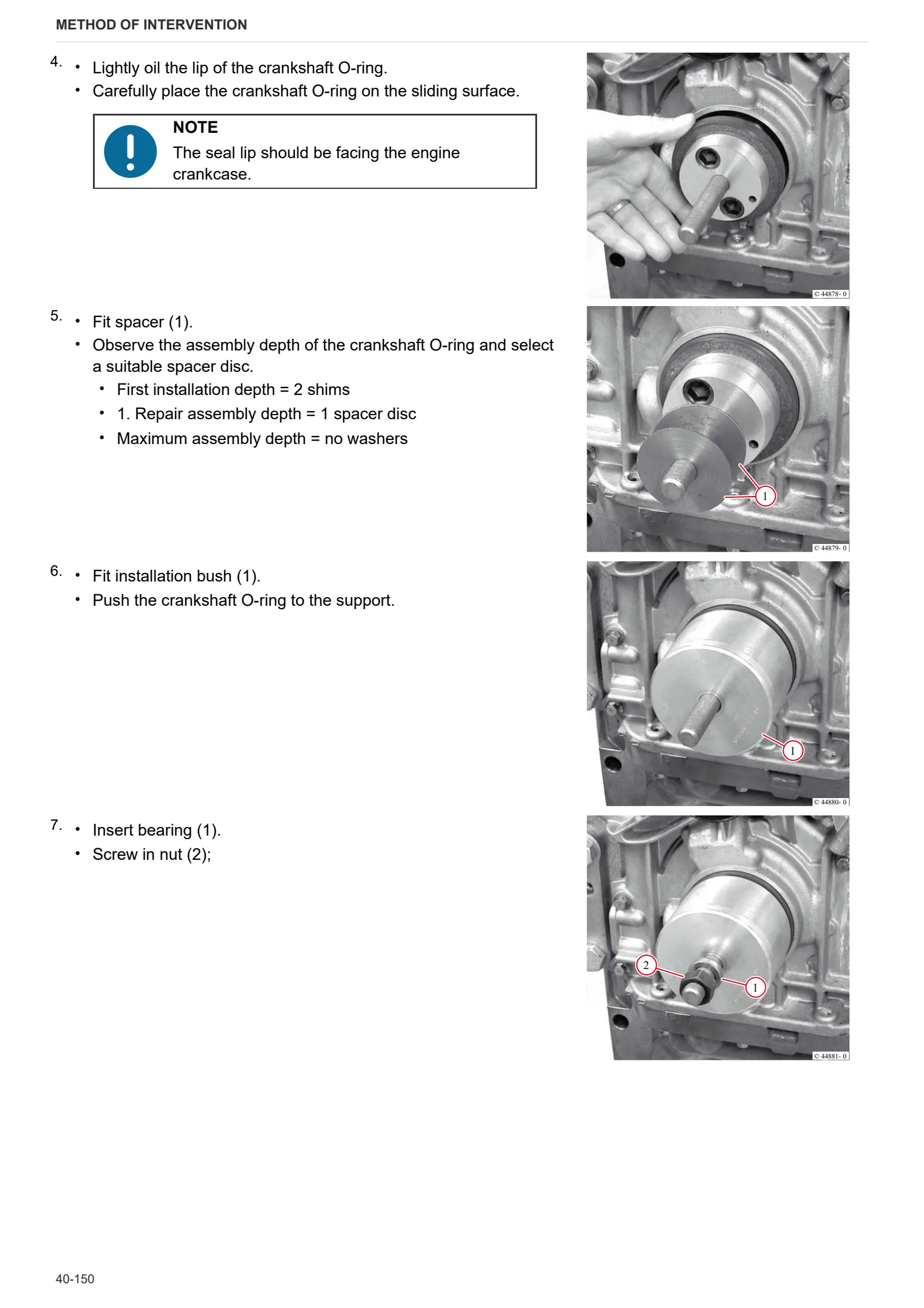
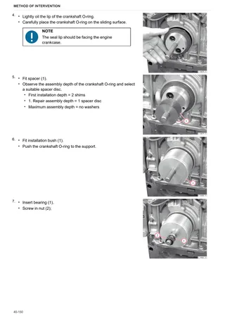
- Replace the crankshaft O-ring (flywheel end)
- Replacing the crankshaft O-ring (opposite end to flywheel)
- Check the connecting rod drum
- Assembly and disassembly of the crankshaft
- Disassembly and assembly of the piston and connecting rod drum
- Check the piston
- Check the piston rings and piston grooves
- Assembly and disassembly of piston cooling nozzles
- Removal and refitting of the crankcase breather
- Check the cylinder
- Removal and refitting of the front cover (opposite end to flywheel)
- Disassembly and assembly of the gear case cover
- Assembly and disassembly of the camshaft
- Check the camshaft
- Removal and refitting of the rotation device
- Removal and refitting of the heater
- Removal and refitting of the turbocharger
- Removing and fitting the butterfly valve (exhaust gas recovery)
- Removing and fitting the cooler (exhaust gas recovery)
- Removing and fitting regulator unit (exhaust gas recovery)
- Removing and fitting the cutoff valve (exhaust gas recovery)
- Adjusting the cutoff valve (exhaust gas recovery)
- Removing and fitting the fuel delivery pump (driven by ribbed V-belt) (L3)
- Removal and refitting of the fuel control unit
- Removal and refitting of the high-pressure pump (installation position A)
- Removal and refitting of the high-pressure pump (installation position B)
- Removal and refitting of the common rail
- Removal and refitting of the injectors
- Removal and refitting of the pressure cut-off valve
- Removal and refitting of the oil sump pan.
- Removal and refitting of the oil pickup pipe
- Removal and refitting of the oil cooler
- Removal and refitting of the lube oil cooler housing
- Removal and refitting of the water pump
- Testing the thermostat (after removal)
- Removal and refitting of the fan drive system
- Removal and refitting of the fan drive system
- Removal and refitting of the torsional vibration damper
- Removing and fitting belt tensioner (ribbed V-belt)
- Removal and refitting of the flywheel
C0 – Engine accessories
- Disassembly and assembly of the speed indicator (crankshaft)
- Removal and refitting of the camshaft speed sensor
- Removal and refitting of the exhaust manifold
- Removal and refitting of the fuel filter head.
- Removal and refitting of the rail pressure sensor
- Remove and install the heating flange
- Removing and fitting the alternator (driven by ribbed V-belt) (L3)
- Disassembly and assembly of the starter
- Removal and refitting of the supply air pressure/temperature sender
D0 – Transmission
- Separating rear axle from transmission
- Attaching rear axle to gearbox
- PTO Transmission – Disassembly
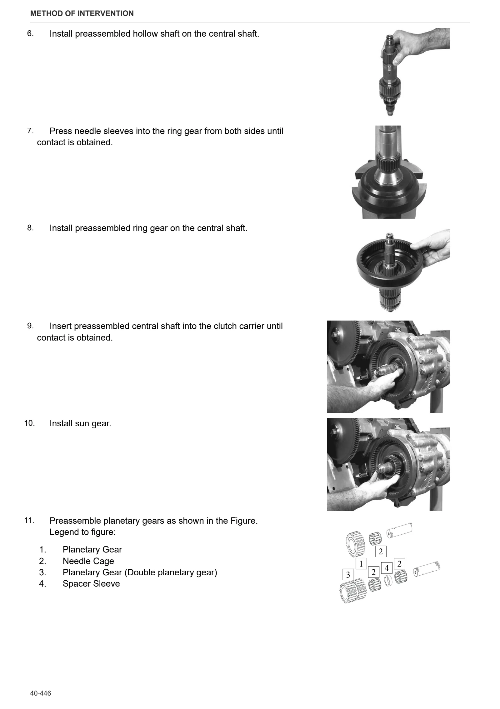
- Fitting the PTO transmission
- Removal of cartridge
- Disassembly of shifting drum
- Disassembly of P1 ring gear carrier
- Disassembly of P1/P2 Planetary drive
- Disassembly of P5/P6 Planetary drive
- Disassembly of KV clutch
- Disassembly of K1 clutch
- Disassembly of K3/K4 clutch and P3/P4 planetary drive
- Disassembly of K3/K4 clutch
- Disassembly of P3/P4 planetary drive
- Disassembly of KR clutch
- Disassembly of K2 clutch
- Disassembly of hydrostatic unit
- Disassembly of control (TCU)
- Disassembly of pump
- Disassembly of suction filter
- Disassembly of filter head
- Disassembly of pressure relief valves
- Disassembly of control unit
- Disassembly of valves, pressure sensor, inductive sensors
- Disassembly of wiring harness, valve block and plate
- Disassembly of valve block (filter head, pressure relief valves, thermocouple)
- Disassembly of valve block (all-wheel-drive / park lock)
- Disassembly of valve block (hydraulic control)
- Disassembly of valve block (pressure reducing valve)
- Disassembly of wiring harnesses and control unit
- Disassembly of inductive sensors
- Disassembly of plug-in module
- Disassembly of clutch (all-wheel-drive)
- Disassembly of spur gear
- Disassembly of pinion
- Disassembly of park lock
- Disassembly of output shaft
- Disassembly of intermediate housing
- Disassembly of drive shaft
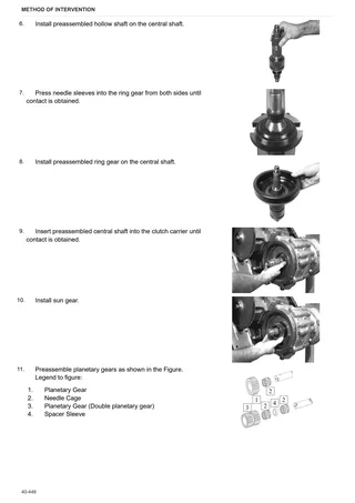
- Preassembly of transmission housing
- Reassembly of drive shaft
- Reassembly of intermediate housing
- Reassembly of pinion
- Reassembly of park lock
- Reassembly of clutch (all-wheel-drIve)
- Reassembly of spur gear
- Reinstallation of plug-in module
- Reassembly of output shaft
- Preassembly of housing lid
- Reassembly of plate
- Reassembly of valve block
- Reassembly of wiring harnesses
- Reassembly of inductive sensors, pressure sensors, valves
- Reassembly of control unit (hydrostatic unit)
- Reassembly of pressure relief valves (PRV)
- Reassembly of filter head
- Disassembly of wiring harnesses and control unit
- Reassembly of wiring harnesses and control unit
- Reassembly of valve block (pressure reducing valve)
- Reassembly of valve block (hydraulic control)
- Reassembly of valve block (all wheel-drive / park lock)
- Reassembly of valve block (filter head, pressure relief valves, thermocouple)
- Reassembly of pump
- Reassembly of control
- Reassembly of hydrostatic unit
- Reassembly of suction filter
- Reassembly of K2 Clutch
- Reassembly of KR clutch
- Reassembly of P3/P4 planetary drive
- Reassembly of K3/K4 clutch
- Reassembly of K1 Clutch
- Reassembly of KV Clutch
- Reassembly of P5/P6 planetary drive
- Reassembly of P1/P2 planetary drive
- Reassembly of P1 Ring gear carrier
- Reinstallation of cartridge
E0 – Rear axle
- Axle Stub – Disassembly
- Axle Stub – Assembly
- Brake Disassembly
- Brake Assembly
- Differential – Disassembly
- Fitting the differential
- Oil Supply – Disassembly
- Oil Supply – Assembly
- Rear Axle Housing – Preassembly
- Procedure for checking EPB travel
F0 – Front axle
- Toe-in/steering angle/assembly tests
- Steering cylinders assembly
- Axle shaft assembly
- Flange assembly
- Differential assembly – carrier
- Checking the bevel gear pair
- Differential disassembly
- Axle pivot bearings assembly
- Bevel pinion assembly
- Planetary reduction gear assembly
- Wheel hub assembly
- Brake assembly
L0 – Electrical system
- Steering position sensor assembly
R0 – Rear lift
- Lifting Unit – Disassembly
- Lifting Unit – Assembly
V0 – Ballast – towing hitches
- Tightening Torques for Tow Hitches
- Standard fastener hardware: Tightening torque/Tension forces
V1 – AFTERMARKET KITS
- Installation of the air conditioning kit
- Installing supplementary fuse box kit
Wiring diagrams
Introduction
- Introduction
- Basic electronics for mechanics (1/2)
- Basic electronics for mechanics (2/2)
- Electrical and electronic components (1/2)
- Electrical and electronic components (2/2)
Components
- A – Starting and charging
- B – Valves and fuses box
- C – Earths
- D – Intermediate connections
- E – On-board instruments and visual and audible indicators
- F – External lights
- G – Interior lights
- H – Electrical and manual controls
- I – Circuit breakers
- J – Relays
- K – Sensors and transmitters
- L – Electromagnets and solenoid valves
- M – Electrical/electronic devices, flasher units and timers
- N – Electric motors and actuators
- O – Resistors, rheostats, diodes and diode boards
- P – Various services
- R – Diagnostics
- 04214367 – Engine control unit
- 2.8519.085.0/10 – Transmission control unit
Systems
- S001 – Engine
- S002 – Transmission
- SO03 – Front axle suspension
- S004 – Instrument panel
- S005 – Lights – Version without front lift
- S005a – Direction indicators – Version without front lift
- S006 – Lights – Version with front lift
- S006a – Direction indicators – Version with front lift
- S007 – Worklights – Version without front lift
- S008 – Worklights – Version with front lift
- S009 – Semi-active cab suspension
- S010 – Air conditioning
- S011 – Positives
- S011a – Positive +30
- S012 – Negatives
- S013 – CAN BUS – Standard version
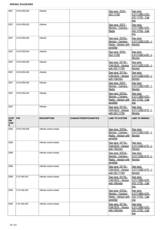
- S013a – CAN BUS – Version with I-Monitor
- S013a – CAN BUS – Version with I-Monitor
- S013b – CAN BUS – Version with ISO 11783
- S014 – PTO
- S015 – Front and rear lifts
- S016 – Brakes
- S017 – Trailer air braking
- S018 – Hydraulic control valves
- S019 – Windscreen wipers
- S020 – Radio
- S021 – Accessories
- S022 – Diagnostics
- S023 – Monitor – Camera – Radio
- S023a – Monitor – Camera – Radio – Version with amplifier
- S024 – Positives (U.S.A.)
- S024a – Positive +30 (U.S.A.)
- S025 – Transmission (U.S.A.)
- S026 – Lights – Version without front lift (U.S.A.)
- S027 – Lights – Version with front lift (U.S.A.)
- S028 – Direction indicators (U.S.A.)
- S029 – Worklights – Version without front lift (U.S.A.)
- S030 – Worklights – Version with front lift (U.S.A.)
- S031 – PTO (U.S.A.)
- S032 – Brakes (U.S.A.)
- S033 – Trailer air braking (U.S.A.)
- S034 – ISO 11783
Wiring harnesses
- 0.012.2018.4/20 – Number plate light
- 0.013.4085.4/20 – Front LH outer worklight on hood
- 0.013.4085.4/20 – LH inner worklight on hood
- 0.013.4085.4/20 – Centre worklights on hood
- 0.013.4085.4/20 – RH Inner worklight on hood
- 0.013.4085.4/20 – RH outer worklight on hood
- 0.014.0007.4/10 – Lights selector switch
- 0.014.4992.4/10 – Agrosky
- 04422156/20 – Battery positive – Version with 1 tank
- 0.014.5132.4/10 – Battery positive – Version with 2 tanks
- 0.014.5144.4/10 – Battery negative
- 0.015.3974.4/10 – Front axle suspension
- 0.015.5429.4/20 – Front lift control
- 0.015.7505.4 – Front screen washer pump
- 0.015.7505.4 – Rear screen washer pump
- 0.016.0234.4/30 – Semi-active cab suspension
- 0.016.0642.4/20 – Rear RH lower worklights on cab (Xenon)
- 0.016.0642.4/20 – Rear lower worklights on cab (Xenon)
- 0.016.0650.4/10 – Front RH lower worklights on cab (Xenon)
- 0.016.0650.4/10 – Front LH lower worklights on cab (Xenon)
- 0.016.0867.4/80 – Side console
- 0.016.0868.4/40 – LH transmission
- 0.016.0869.4/70 – RH transmission
- 0.016.0871.4/30 – Front console
- 0.016.3980.4/30 – Front console (U.S.A.)
- 0.016.3987.4/80 – Side console (U.S.A.)
- 0.016.3997.4/30 – LH transmission (U.S.A.)
- 0.016.6244.4/10 – Power supplies
- 0.016.7899.4 – Engine hood
- 0.017.0052.4/10 – Roof
- 0.017.0053.4/20 -RH fender
- 0.017.0053.4/20 – LH fender
- 0.017.0164.4 – Rear camera
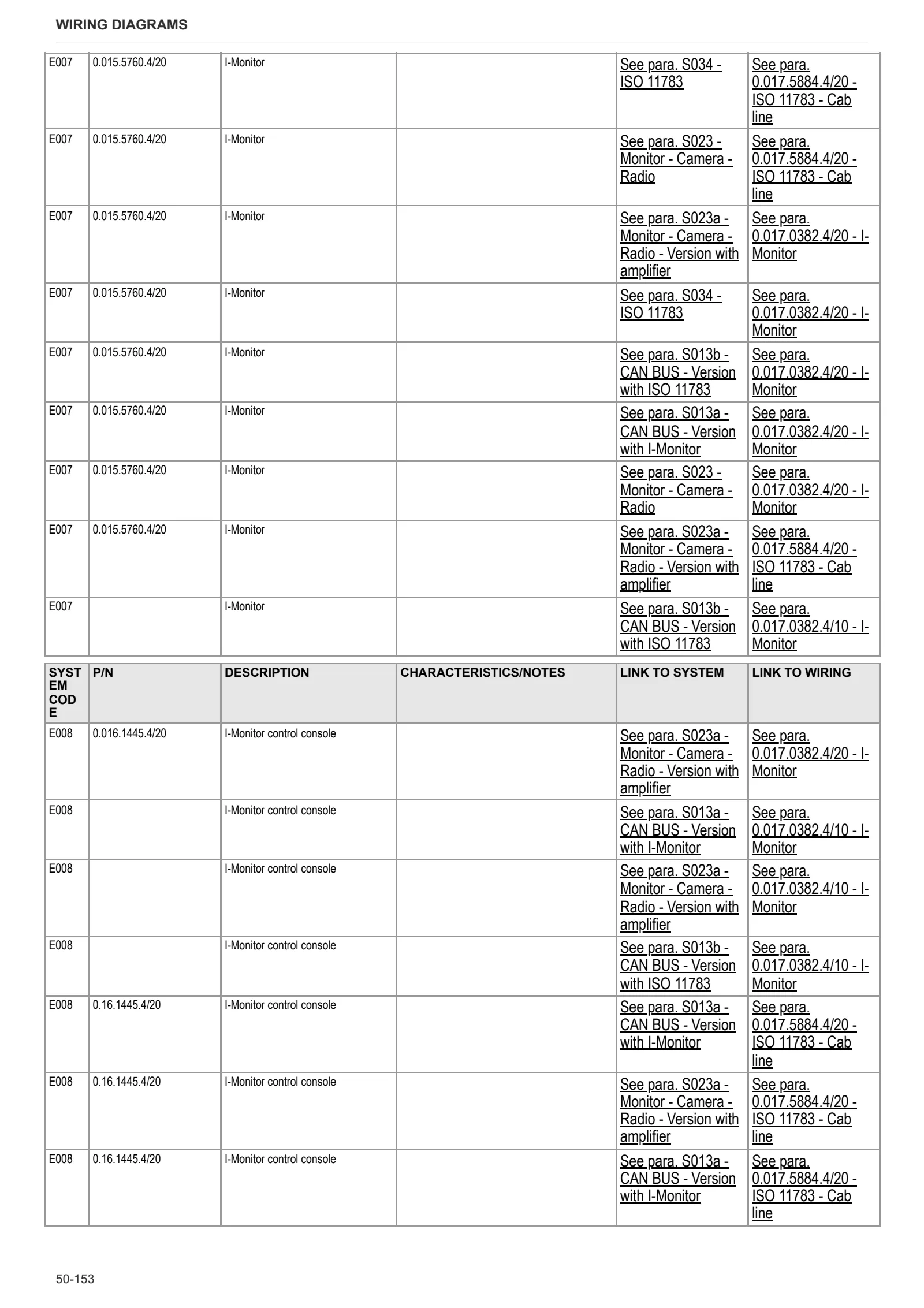
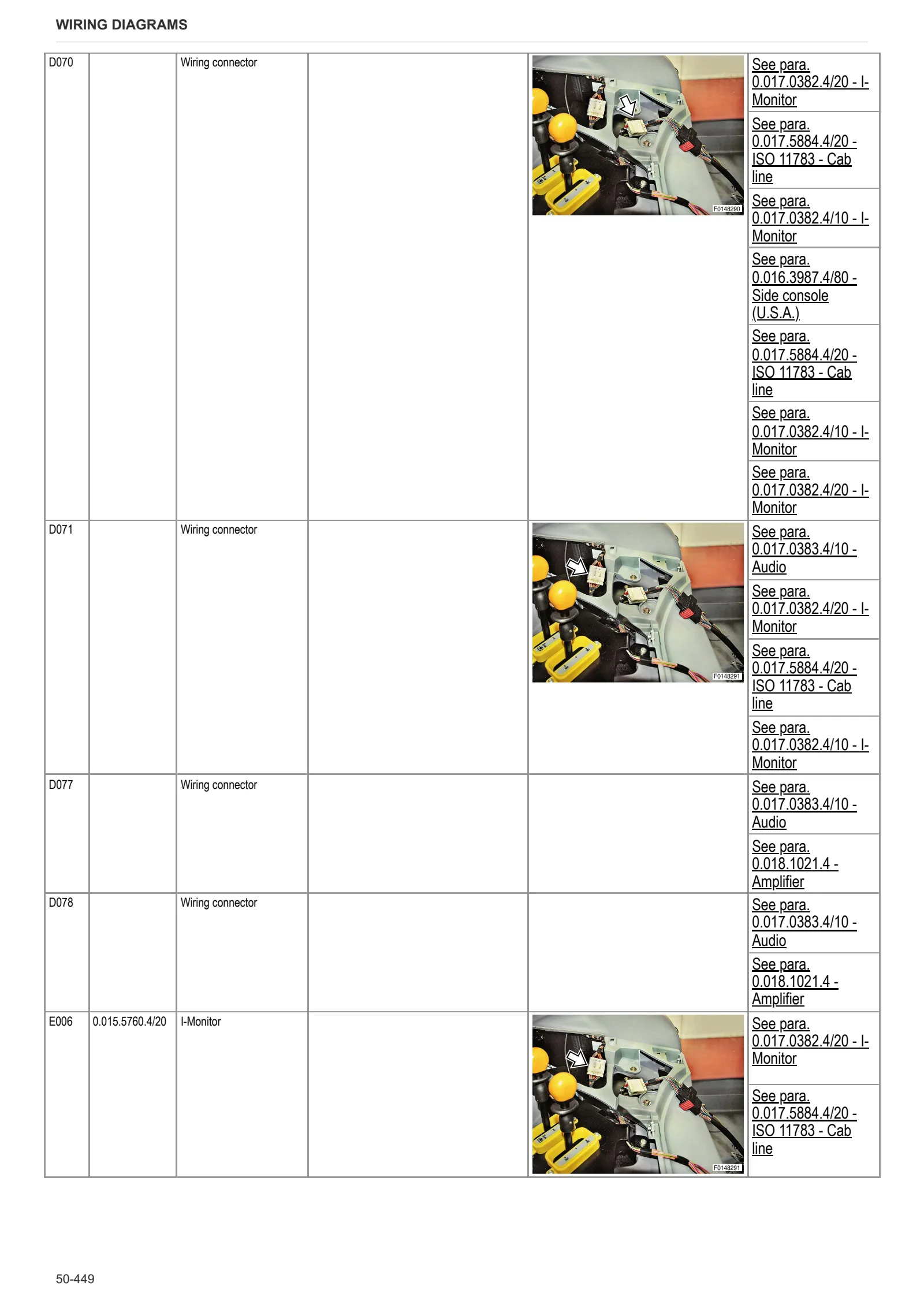
- 0.017.0382.4/10 – I-Monitor
- 0.017.0382.4/20 – I-Monitor
- 0.017.0383.4/10 – Audio
- 0.017.0496.4/10 – Supplementary RH worklight on arm
- 0.017.0496.4/10 – Supplementary LH worklight on arm
- 0.017.0789.4/10 – LH fender (U.S.A.)
- 0.017.0789.4/10 -RH fender (U.S.A.)
- 0.017.5493.4 – Worklights control relay
- 0.017.5884.4/20 – ISO 11783 – Cab line
- 0.017.5885.4/20 – ISO 11783 – Rear line
- 0.017.8887.4/10 – ISO 11783 – Front line
- 0.018.1021.4 – Amplifier
- 0.900.1421.0 – Air conditioning
- 04214410 – Fuel injectors
- 04216076 – Engine
- 04411923.4 – Front LH lower worklights on cab
- 04411923.4 – Front RH lower worklights on cab
- 04412045 – Windscreen wiper motor
- 04428092.4 – Front LH sidelight and direction indicator
- 04428092.4 – Front RH sidelight and direction indicator
- 04436707 – Rotating beacon
- 04437355.4/10 – Air braking pressure switch
Service Info
A0 – TRACTOR
- Diagnostics 2026 subscription
- After-sales 2026 subscription
- SERVICE NEWS RESEARCH GUIDE
- Diagnostics 2025 subscription
- After-sales 2025 subscription
- Diagnostics 2023 subscription
- Diagnostics 2024 subscription
- Diagnostics 2022 subscription
- Diagnostics 2021 subscription
- Technical Documentation DVD 06/2009
- SDF LUBRICANTS: Lubricant oils and coolant fluids
- After-sales 2024 subscription
- After-sales 2023 subscription
- After-sales 2022 subscription
- After-sales 2021 subscription
- After-sales 2019 subscription
- SDF Parts and SDF Service DVV 04/2014, version 26
- Technical Documentation DVD 03/2010
- New function: Download PDF manuals
- Diagnostics – 2020 subscription
- After-sales – 2020 subscription
- After-sales – 2018 subscription
- Service and Spare Parts – 2017 Subscription
- SDF Parts and SDF Service DVDs 05/2014 version 25
- SDF Parts and SDF Service DVDs 03/2013 version 24
B0 – ENGINE
- Flushing the lubrication circuit
- Deutz AG engine oil specifications
- SerDia 2010 updating license file
C0 – ENGINE ACCESSORIES
- Diagnostic protocol – AdBlue – Float level unit
- Filter and prefilter tool p/n 5.9035.865.0
- Additive for diesel fuel
D0 – TRANSMISSION
- Rear pinion support flange
F0 – FRONT AXLE
- Check the front axle steering knuckles for wear
- Steering behavior check procedure
G0 – BODYWORK – CAB
- Air conditioning system filter-drier
- Air conditioning system recharging
H0 – HYDRAULIC AND PNEUMATIC SYSTEM|
- Hydraulic CUNA trailer braking kit (ITALY)
- Single connection hydraulic braking kit availability update – only for EUROPEAN market
- Resonator failure
- Assembly instructions for solenoid valves and cartridge valves
- Pressure line from variable displacement pump
- L0 – ELECTRIC AL SYSTEM