
Document overview
Workshop Manual for LAMBORGHINI R3 EVO 110 → ZKDL8102W0TL1001 from the R3 EVO (STAGE 3A) family. Digital PDF in English with 1,632 pages.
The corresponding English table of contents contains 50 sections and 403 individual topics.
Main sections included
- Introduction
- Safety
- Technical characteristics
- Calibrations and electronic diagnosis
- Method of intervention
- Wiring diagrams
- Service Info
Document details
- Brand: LAMBORGHINI
- Family: R3 EVO (STAGE 3A)
- Model: R3 EVO 110
- Starting serial number: ZKDL8102W0TL1001
- Document type: Workshop Manual
- Language: English
- Pages: 1,632
- File size: 186.81 MiB
- Format: Digital PDF download
Compatibility
Before purchasing, verify that your machine model and reference code match LAMBORGHINI R3 EVO 110 → ZKDL8102W0TL1001.
Complete table of contents
Introduction
- Introduction – Engines
- Tightening torques
- Tightening torques for nuts and bolts of electrical connections
- Wheel nut/screw tightening torques
- Installation of solenoid valves and cartridge valves
- Installation of quick couplers
- Units of measurement and conversion factors
Safety
Preface
- Important notes concerning safety
Important safety information
- Recognising hazards
- Indications for persons in contact with the tractor
Safety rules
- Risks during tractor preparation
- Risks during maintenance
- Work on machine systems
- Special disassembly/assembly/inspection procedures
Safety pictograms
- Replacing safety pictograms
Environmental risks
- Hazards associated with the operating environment
Technical characteristics
Engine
- Components of the 2012 2V UPS engine
- Test data and settings
- Tightening requirements 2012 2V UPS engine
Transmission
- Transmission
- Rear PTO
- 2 and 4-speed PTO and Syncro PTO
- Hydraulic reverse power shuttle
Front axle
- Front axle
Hydraulic system
- Hydraulic system
- Steering circuit pump – lift circuit pump
- Power steering valve
- Remote control valve – 6-way version
- Hydraulic lift control valve
- Braking system
- Trailer braking valve
- Park Brake system
- Park Brake valve
- Services solenoid valves assembly – Pressure holding valves
- Shuttle solenoid valves assembly
Calibrations and electronic diagnosis
Diagnostic tools
- Position of ECUs and diagnostic instruments
SDF Analyser
- SDF Analyser
- SDF Analyser – Diagnostic socket
Serdia 2000
- SERDIA 2000 level III” software
Diagnostic tool screens
- ECU interrogation
Commissioning and calibrating the tractor
- Digital instrument calibration
- Renewal of the shuttle ECU – Introduction
- Renewal of the shuttle ECU – Initialisation of the ECU
- Renewal of the shuttle ECU – Line end programming
- Renewal of the shuttle ECU – Introductory notes
- Renewal of the shuttle ECU – Automatic calibration
- Renewal of the shuttle ECU – Manual calibration
- Renewal of the shuttle ECU – Editing the comfort parameters
- Renewal of the shuttle ECU – Calibration of the clutch pedal
- Renewal of the engine ECU – Introduction
- Renewal of the engine ECU – Calibration of the accelerator pedal
- Renewal of the engine ECU – Calibration of the hand throttle lever
ECU alarms
- Key to the “ECU alarms” tables
- FMI code
Engine alarms
- Alarms – Engine alarms list
Transmission alarms
- Alarms – Transmission alarms list
Instrument panel alarms
- Alarms – Instrument panel alarms list
- P.T.O. selfdiagnosis indicator light.
Method of intervention
- Tools for engine disassembly and reassembly
- Workshop tools for engine disassembly and reassembly
B0 – Engine
- Air conditioning compressor drive belt
- Tension adjustment of the fan and air conditioning compressor drive belt
- Alternator, fuel pump and water pump drive belt
- Tension adjustment of the alternator, fuel pump and water pump drive belt
- Compression test
- Assembly and disassembly of the engine on the assembly stand
- Adjustment of valve clearance
- Removal and refitting of the rocker arms and pedestals
- Disassemble and complete the rocker and support, check
- Disassembly and assembly of the cylinder head
- Grinding the cylinder head seal surface
- Measuring piston protrusion
- Valve assembly and disassembly
- Valve check
- Check the valve guide
- Replacing the valve guide (oversized – cast)
- Check the valve residual
- Replacing the lined valve seat (oversized)
- Check the endfloat of the crankshaft
- Check the crankshaft
- Replace the crankshaft O-ring (flywheel end)
- Replacing the crankshaft O-ring (opposite end to flywheel)
- Check the connecting rod drum
- Fitting and removing piston pin bush
- Assembly and disassembly of the crankshaft
- Fitting and removing counterweight shafts, checking
- Disassembly and assembly of the piston and connecting rod drum
- Check the piston
- Check the piston rings and piston grooves
- Assembly and disassembly of piston cooling nozzles
- Removal and refitting of the crankcase breather
- Check the cylinder
- Removal and refitting of the front cover (opposite end to flywheel)
- Disassembly and assembly of the connector box
- Fitting and removing the camshaft bearings, checking
- Disassembly and assembly of the gear case cover
- Assembly and disassembly of the camshaft
- Check the camshaft
- Removal and refitting of the rotation device
- Removing and fitting the V-belt pulley
- Fitting, removing, checking and setting adjuster rod
- Removal and refitting of the heater
- Removal and refitting of the turbocharger
- Removal and refitting of the charge air duct
- Fitting and removing injection pump
- Determine the thickness of the shim (engine without injection advance variator)
- Determine the thickness of the shim (engine with injection advance variator)
- Determination of the overall dimensions of the injection pump (engine without the injection advance variator)
- Determination of the overall dimensions of the injection pump (engine with the injection advance variator)
- Fitting and removing injection valves
- Checking the injection valves
- Removal and refitting of the fuel lift pump
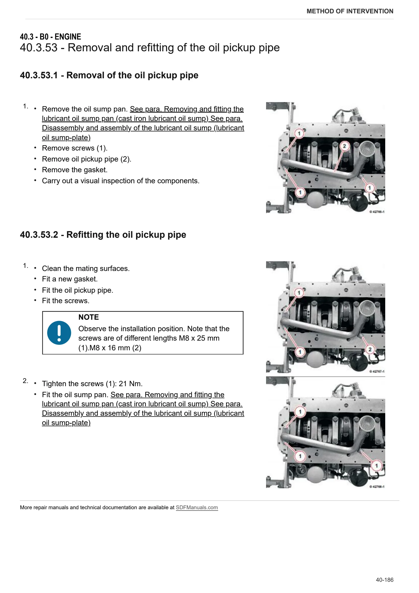
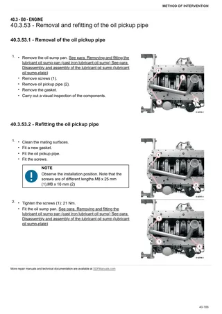
- Removal and refitting of the oil pickup pipe
- Removing and fitting the lubricant oil sump pan (cast iron lubricant oil sump)
- Disassembly and assembly of the lubricant oil sump (lubricant oil sump-plate)
- Removal and refitting of the oil cooler
- Disassembly and assembly of the oil radiator housing
- Removal and refitting of the oil pressure switch
- Removal and refitting of the water pump
- Testing the thermostat (after removal)
- Removal and refitting of the thermostat
- Removal and assembly of the fan support
- Removal and refitting of the fan support
- Removal and refitting of the flywheel
- Replacing the starter motor ring gear on the flywheel
C0 – Engine accessories
- Starter motor
- Removing and fitting the engine governor
- Removal and refitting of the exhaust manifold
- Removal and refitting of the fuel filter head.
- Assembly and disassembly of the temperature sender
- Removal and refitting the engine block
- Removal and refitting of the alternator (with drivebelt)
- Disassembly and assembly of the starter
D0 – Transmission
- Changing the transmission oil
- Range selector assembly
- Disassembly of the range selector
- Separation of housing from transmission
- Shuttle assembly – complete unit
- Disassembly of the shuttle unit
- Disassembly of the cover unit
- Disassembly of the forward drive clutch assembly
- Disassembly of the reverse drive clutch assembly
- Gearbox and Hi-Lo assembly
- Disassembly of the Hi-Lo unit
- Disassembly of the planet carrier
- Disassembly of the Hi range clutch housing
- Hi-Lo unit output shaft disassembly procedure
- Disassembly of the gearbox input shaft
- Torsional spring plate
- Disassembly of the primary shaft – Version with Hi-Lo
- Secondary shaft – Version with Hi-Lo
- Disassembly of the secondary shaft – Version with Hi-Lo
- Range gearbox and differential assembly – complete assembly
- Complete gearbox assembly – Version with Hi-Lo
- Adjustment of the differential – Bevel gear pair
- Disassembly of the rear pinion
- Disassembly of the 4WD output shaft
- PTO clutch.
- Disassembly of the PTO clutch
- Pump drive PTO – Outer gear
- Pump drive PTO – Inner gear
- PTO output shaft – 4 speed version
- Disassembly of the PTO output shaft – 4 speed version
- Disassembly of the Groundspeed PTO output shaft
- Disassembly of the Groundspeed PTO engagement device
- Disassembly of the 4WD engagement device – Easyshift
E0 – Rear axle
- Right-hand rear axle
- Disassembly of LH/RH rear axle
- Left-hand rear axle
- Disassembly of the planet carrier
- Rear differential
- Disassembly of the rear differential
- Park Brake assembly
- Park Brake unit disassembly
F0 – Front axle
- Separation of front support from engine
- Front support
- 4WD front axle
- Adjusting the front axle end float
- Steering cylinders
- Steering cylinders disassembly
- Steering knuckle housing and half-shaft
- Adjustment of steering knuckle housing and axle shaft
- Differential unit
- Differential disassembly
- Differential unit adjustment
- Bevel gear pair
- Adjustment of the bevel gear pair
- Disassembly of the differential
- 4WD shaft
- Planetary reduction gear
- Disassembly of the planetary reduction gearbox
- Front brake discs
- Front axle brake piston
G0 – Bodywork – Cab – Platform
- Cab
- Front hood and side panels
- Battery support
- Cab access steps
- Fenders
- Right-hand console
- Left-hand console
- Front instrument panel
- Roof lining – Version with high visibility cab
- Heating fan – Version with high visibility cab
- Air conditioning system controls – High-visibility roof system
- A/C system – Version with standard roof
- Heating and air conditioning unit – Version with high visibility cab
- Heating control cable
- Condenser – Version with high-visibility roof
- Receiver drier – Version with high visibility roof
- Conditioner evaporator – Version with standard roof
- Air-conditioning evaporator – Version with high-visibility roof
- Heating valve – Version with high visibility cab
- Heater matrix – Version with high-visibility roof
- Heating radiator – Version with standard roof
- Heating and air conditioning unit fan – Version with standard roof
- Expansion valve – Version with high visibility roof
- Expansion valve – Version with standard roof
- Antifreeze sensor – Version with high visibility roof
- Condenser cooling fans – Version with high-visibility roof
- Condenser fan control pressure switch – Version with high visibility roof
- Air conditioning temperature control thermostat – Version with standard roof
- Remote valve control cables
- Adjustment of the control levers
H0 – Hydraulic system
- Pump for hydraulic lift and auxiliary services
- Power steering valve
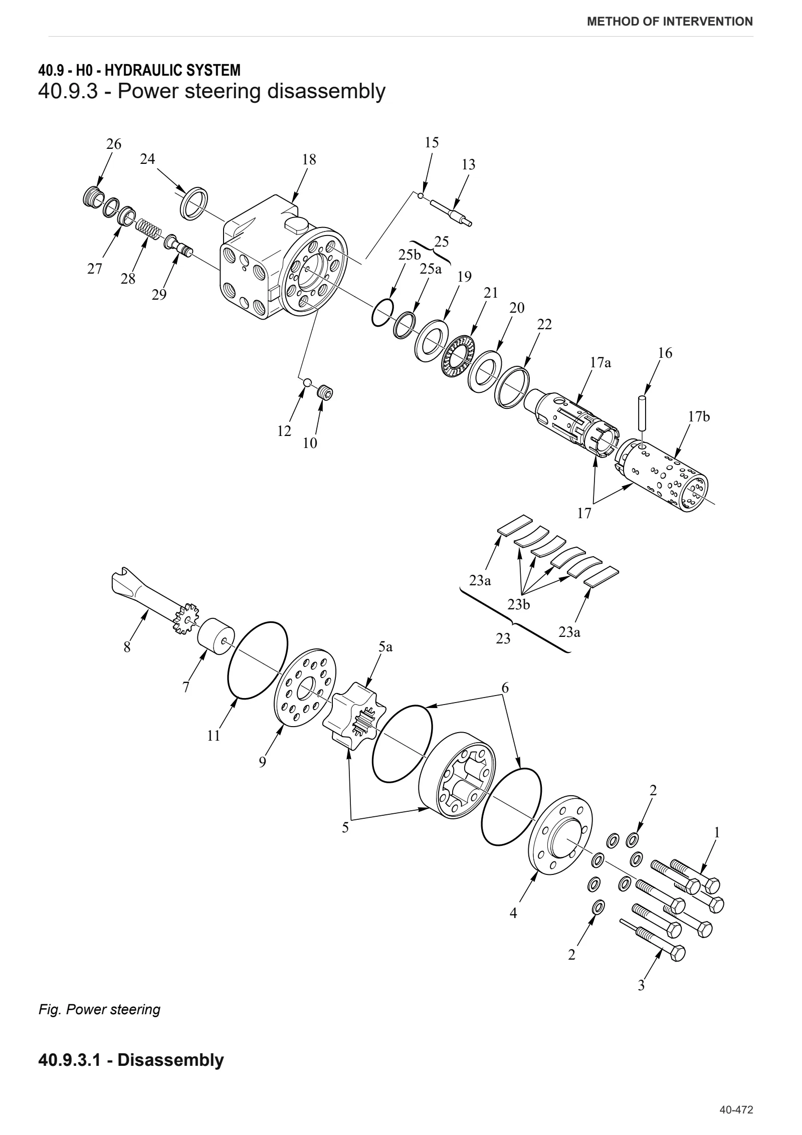
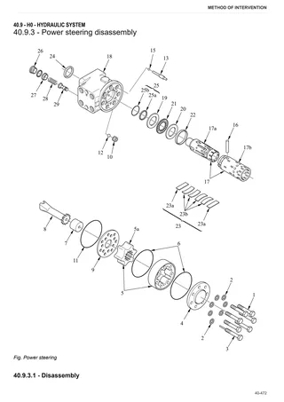
- Power steering disassembly
- Pressure relief valve setting
- Power steering pump
- GEARBOX OIL COOLER
- Rear remote control valve
- Bleeding the braking circuit
- Parking brake control valve
- Braking distributor valve
- Services solenoid valve assembly
- Pressure reduction and holding valve disassembly
- Shuttle solenoid valves assembly
L0 – Electrical system
- Lateral battery
- Alternator
- Clutch pedal potentiometer
- Shuttle output speed sensor
- Accelerator pedal position sensor
- Hand throttle position sensor
- Steering column switch
- Shuttle ECU and forward/reverse selector
M0 – Front PTO
- Front PTO
- PTO assembly.
- Pump assembly
- Front PTO oil cooler
- Clutch-brake assembly
- Solenoid valve assembly
N0 – Front lift
- Front lift
- Disassembly of front lift cylinders
R0 – Rear lift
- Lift – Complete assembly
- Disassembly of the lift- complete assembly
- Lift cylinder
- Bushes
- Auxiliary lift cylinders
- Disassembly of the lift control valve
- Mechanical draft sensor
- Mechanical draft sensor disassembly
- 3-point linkage
S0 – Wheels
- Front wheels
- Rear wheels
V0 – Ballast – towing hitches
- Towing hitch slide
Wiring diagrams
Introduction
- Introduction
- Basic electronics for mechanics (1/2)
- Basic electronics for mechanics (2/2)
- Electrical and electronic components (1/2)
- Electrical and electronic components (2/2)
Components
- A – Starting and charging
- B – Fuses
- C – Earths
- D – Intermediate connections
- E – On-board instruments and visual and audible indicators
- F – External lights
- G – Interior lights
- H – Electrical and manual controls
- I – Circuit breakers
- J – Relays
- K – Sensors and transmitters
- L – Electromagnets and solenoid valves
- M – Electrical/electronic devices, flasher units and timers
- N – Electric motors and actuators
- O – Resistors and rheostats
- P – Various services
- R – Diagnostics
- T – Power supply points (+15 o +30)
Systems
- S001 – Starting and preheating
- S002 – Electronic engine governor
- S003 – Diagnostics and accessories – Version with standard cab
- S004 – Diagnostics and accessories – Version with high-visibility cab
- S005 – Instrument panel
- S006 – Work lights – Version with standard cab without front lift
- S007 – Work lights – Version with standard cab with front lift
- Work lights – Version with high-visibility cab without front lift
- S009 – Work lights – Version with high-visibility cab with front lift
- S010 – Heating – Version with standard cab
- S011 – Heating – Version with high-visibility cab
- S012 – Manual climate control – Version with standard cab
- S013 – Manual climate control – Version with standard cab
- S014 – Manual climate control – Version with high-visibility cab
- S015 – Steering column lights switch – Version with cab without front lift
- S016 – Steering column lights switch – Version with cab with front lift
- S017 – +30 Positives
- S018 – +15 Positives
- S019 – Windscreen wipers – Version with standard cab
- S020 – Windscreen wipers – Version with high-visibility cab
- S021 – Transmission
- S022 – PTO
- S023 – Can Bus
- S024 – Brakes
- S025 – Negatives
- S026 – Steering column lights switch – Version with cab without front lift (U.S.A.)
- S027 – Steering column lights switch – Version with cab with front lift (U.S.A.)
- S028 – PTO (U.S.A.)
- S029 – Brakes (U.S.A.)
Wiring harnesses
- 0.008.0913.3 – Front PTO
- 0.009.7853.3/20 – Air conditioning condenser fan – Version with standard cab
- 0.010.2147.2 – Heating – Version with standard cab
- 0.010.2153.2 – Air conditioning – Version with standard cab
- 0.010.4516.3 – Windscreen wiper – Version with standard cab
- 0.011.3597.3 – Windscreen wiper – Version with high-visibility cab
- 0.013.4909.4 – Rear lights (U.S.A.)
- 0.013.6327.4 – LH rotating beacon
- 0.013.6327.4 – RH rotating beacon
- 0.014.1645.4/10 – Compressed air pressure sensor
- 0.014.3927.4/40 – LH auxiliary work lights – Version with high-visibility cab
- 0.014.3927.4/40 – RH auxiliary work lights – Version with high-visibility cab
- 0.014.8107.4/30 – Hood lights
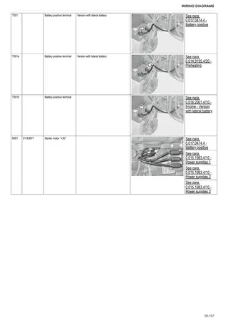
- 0.014.9195.4/20 – Preheating
- 0.015.1418.4/30 – Cab shuttle
- 0.015.1435.4/20 – RH auxiliary work lights – Version with standard cab
- 0.015.1435.4/20 – LH auxiliary work lights – Version with standard cab
- 0.015.1983.4/10 – Power supplies 1
- 0.015.1983.4/10 – Power supplies 2
- 0.015.1983.4/10 – Power supplies 3
- 0.015.1998.4/10 – Drivetrain shuttle
- 0.015.6123.4 – Rear wiper – Version with standard cab
- 0.015.6272.4/40 – Cab roof – Version with high-visibility cab
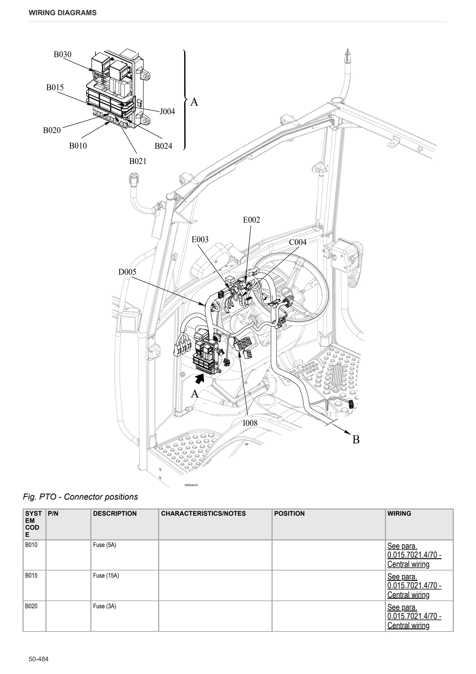
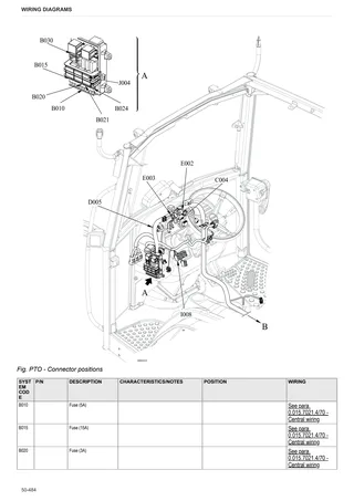
- 0.015.7021.4/70 – Central wiring
- 0.015.7023.4/50 – Drivetrain
- 0.015.7266.4/40 – Air conditioning condenser fan – Version with high-visibility cab
- 0.015.7266.4/40 – Air conditioning condenser fan – Version with standard cab
- 0.016.0373.4/30 – Cab power supply
- 0.016.0484.4/60 – Central (U.S.A.)
- 0.016.0664.4 – Front lights
- 0.016.0865.4/10 – Cab roof – Version with standard cab
- 0.016.0866.4/10 – Front-rear work lights – Version with standard cab
- 0.016.1001.4/20 – Hydraulic trailer braking valve
- 0.016.2000.4/20 – Engine – Version with front battery
- 0.016.2001.4/10 – Engine – Version with lateral battery
- 0.017.0473.4 – Battery negative
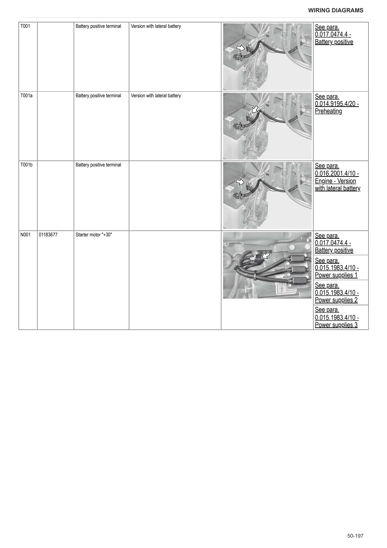
- 0.017.0474.4 – Battery positive
- 0.017.1063.4 – Cab earth
- 0.018.5825.4 – Cab roof – Version with standard cab
- 04215655 – Engine
- 04411923.4 – RH lower headlights
- 04411923.4 – LH lower headlights
Service Info
A0 – TRACTOR
- Diagnostics 2026 subscription
- After-sales 2026 subscription
- SERVICE NEWS RESEARCH GUIDE
- Diagnostics 2025 subscription
- After-sales 2025 subscription
- Diagnostics 2023 subscription
- Diagnostics 2024 subscription
- Diagnostics 2022 subscription
- Diagnostics 2021 subscription
- Technical Documentation DVD 06/2009
- Technical Documentation DVD 07/2008
- SDF LUBRICANTS: Lubricant oils and coolant fluids
- After-sales 2024 subscription
- After-sales 2023 subscription
- After-sales 2022 subscription
- After-sales 2021 subscription
- After-sales 2019 subscription
- SDF Parts and SDF Service DVV 04/2014, version 26
- Technical Documentation DVD 03/2010
- New function: Download PDF manuals
- Diagnostics – 2020 subscription
- After-sales – 2020 subscription
- After-sales – 2018 subscription
- Service and Spare Parts – 2017 Subscription
- SDF Parts and SDF Service DVDs 05/2014 version 25
- SDF Parts and SDF Service DVDs 03/2013 version 24
B0 – ENGINE
- Flushing the lubrication circuit
- Deutz AG engine oil specifications
- SerDia 2010 updating license file
- POSSIBLE LEAKAGE OF FUEL INTO THE ENGINE SUMP (LEVEL RISE)
C0 – ENGINE ACCESSORIES
- Diagnostic protocol – AdBlue – Float level unit
- Filter and prefilter tool p/n 5.9035.865.0
- Additive for diesel fuel
D0 – TRANSMISSION
- Hydraulic shuttle central disc
- Wrong dimension on RPTO stub shaft 21 splines 1-3/8″
- Twisted parking brake lever
- Bushes on shuttle input shafts
F0 – FRONT AXLE
- Check the front axle steering knuckles for wear
- Steering behavior check procedure
G0 – BODYWORK – CAB
- SERVICE NEWS – Brake Fluid Reservoir vent missing
- Clutch pedal potentiometer actuator pin
- Air conditioning system recharging
H0 – HYDRAULIC AND PNEUMATIC SYSTEM|
- Hydraulic CUNA trailer braking kit (ITALY)
- Single connection hydraulic braking kit availability update – only for EUROPEAN market
- Assembly instructions for solenoid valves and cartridge valves
- L0 – ELECTRIC AL SYSTEM