Document overview
Workshop Manual for LAMBORGHINI C.105 → L25Y974WC1001 from the C. family. Digital PDF in English with 527 pages.
The corresponding English table of contents contains 33 sections and 219 individual topics.
Main sections included
- Introduction
- Technical characteristics
- Calibrations and electronic diagnosis
- Method of intervention
- Wiring diagrams
Document details
- Brand: LAMBORGHINI
- Family: C.
- Model: C.105
- Starting serial number: L25Y974WC1001
- Document type: Workshop Manual
- Language: English
- Pages: 527
- File size: 115.85 MiB
- Format: Digital PDF download
Compatibility
Before purchasing, verify that your machine model and reference code match LAMBORGHINI C.105 → L25Y974WC1001.
Complete table of contents
Introduction
- Introduction
- Tightening torques
Technical characteristics
Engine
- Engine block technical data – cylinders
- Crankshaft technical data
- Piston technical data – Piston rings
- Connecting rod technical data
- Camshaft technical data – static advance of 13°
- Camshaft technical data – static advance of 16°
- Timing gears technical data
- Counter-rotating weights technical data
- Technical data and dimensions of valves – valve springs
- Technical data and dimensions of cylinder heads – valve guides – valve seats
- Technical data and dimensions of rocker arms – rocker shafts – tappets
- Engine injector technical data (with turbocharger)
Engine accessories
- Starter motor
Transmission
- Clutch
- Transmission
- Transmission diagram
- Rear PTO
- Hydraulic rear PTO clutch
Rear axle
- Rear axle
- Rear brakes
Hydraulic system
- Hydraulic system
- Hydraulic pumps
- Steering control valve
- Hydrostatic steering pump
- Auxiliary control valve
Electrical equipment
- Battery
- Alternator
Rear lift
- Rear lift
Crawler undercarriage
- Steering clutch
Calibrations and electronic diagnosis
Diagnostic instrument
- SDF Analyser
- SDF Analyser – Diagnostic socket
Diagnostic tool screens
- Preheating control unit
- Engine control unit
- Instrument panel
Commissioning and calibrating the tractor
- Commissioning – Engine ECU – Presentation screen
- Commissioning – Engine ECU – Main menu
- Commissioning – Engine ECU – Configuration
- PC Tester Screens – Engine ECU – Structure
- Commissioning – Engine ECU – Presentation screen
- Commissioning – Engine ECU – Structure
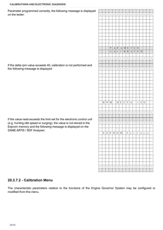
- Commissioning – Engine ECU – Engine menu
- Commissioning – Engine ECU – HML menu
- Commissioning – Engine ECU – Preheating menu
- Commissioning – Engine ECU – Alarms Menu
- Commissioning – Engine ECU – Wheel Calibration Menu
- Commissioning – Engine ECU – Wheels menu
- Commissioning – Engine ECU – HRT Menu
- Commissioning – Engine ECU – DERATING Menu
- Commissioning – Engine ECU – Engine type config.
- Commissioning – Engine ECU – Engine type config.
- Wheels constants
- Commissioning – Engine ECU – Alarms List
- Commissioning – Engine ECU – Functional diagram
- Commissioning – Engine ECU – Special Functions Menu
ECU alarms
Engine alarms
- ECU alarms list
Method of intervention
B0 – Engine
- Engine – transmission
- Engine
- Preliminary and final operations
- Final engine checks
- Checking engine block
- Crankshaft
- Crankshaft checks
- Flywheel checks
- Renewal of crankshaft rear oil seal
- Pistons and cylinder liners
- Cylinder liners check
- Pistons and rings check
- Check connecting rods – gudgeon pins – rod cap screws
- Camshaft
- Camshaft checks
- Timing gear checks
- Adjusting timing gears backlash
- Valve timing
- Counter-rotating weights
- Overhaul of counter-rotating weights assembly
- Counter-rotating weight checks
- Valves check
- Valve seats check
- Valves sealing check
- Valves adjustment
- Valve guides check and replacement
- Inspecting the rocker arms and rocker shafts
- Cylinder heads
- Valve springs check
- Heat exchanger removal
- Disassembly of the heat exchanger
- Lubrication pump
- Lubrication pump disassembly
- Oil sump
- INJECTION PUMPS, GOVERNOR AND FUEL SUPPLY
- Injection pump timing
- Injectors assembly
- Checking injectors protrusion – Renewal of copper bushes
- Injectors check
- Injection pumps control rod
- Overhaul of the mechanical governor (standard and with LDA valve)
- Overhaul of the mechanical governor gear
- Electronic governor adjustment
- Installation of mechanical governor drive unit and electronic governor support
- Engine coolant pump
- Thermostatic valve
- Checking the thermostat valve
- Cooling and intake ducts
C0 – Engine accessories
- Changing the coolant and flushing the circuit
- Engine cooling system radiator.
- Coolant tank
- Cooling fan
- Air cleaner and support
- Right-hand fuel tank
- LH fuel tank
- LH fuel tank float switch
- Starter motor
- Silencer
D0 – Transmission
- Checking the transmission oil level
- Changing the transmission oil
- Changing the transmission oil filter
- Main clutch unit – Assembly
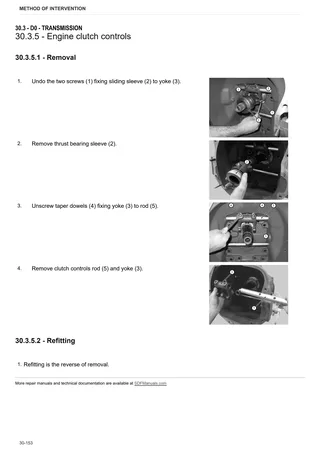
- Engine clutch controls
- Clutch housing
- Gearbox input shaft
- Gearbox input shaft shoe
- Gearbox input shaft shoe adjustment
- Gearbox input shaft oil seal
- Shuttle shaft
- Primary shaft
- Transmission
- Transmission
- Creeper or underdrive internal controls
- Gear control levers
- Secondary shaft and bevel gear pair
- Adjustment of the bevel gear pair
- Creeper or underdrive
- PTO hydraulic clutch
- PTO hydraulic clutch.
- PTO hydraulic clutch adjustment
- PTO gears
E0 – Rear axle
- Final drive half shaft seal
- Final drive
- Crawler track final drive unit pinion
- Final drive disassembly
- Steering clutch disassembly
- Steering clutch – clutch piston
- Crawler track drive clutch
- Brake piston disassembly
- Band brake adjustment
- Brake band
F0 – Front axle
- Front support
G0 – Bodywork – Cab – Platform
- Platform
- Front hood and side panels
- Front grille
- RH fender
- LH fender
- Central platform
- Instrument panel
- Operator’s seat
- Procedure for brake pedals adjustment
- Steering pump levers
- Creeper or underdrive external controls
- Hydraulic levers assembly
- Tool box
- Rear ROPS and components
H0 – Hydraulic system
- Services hydraulic pump
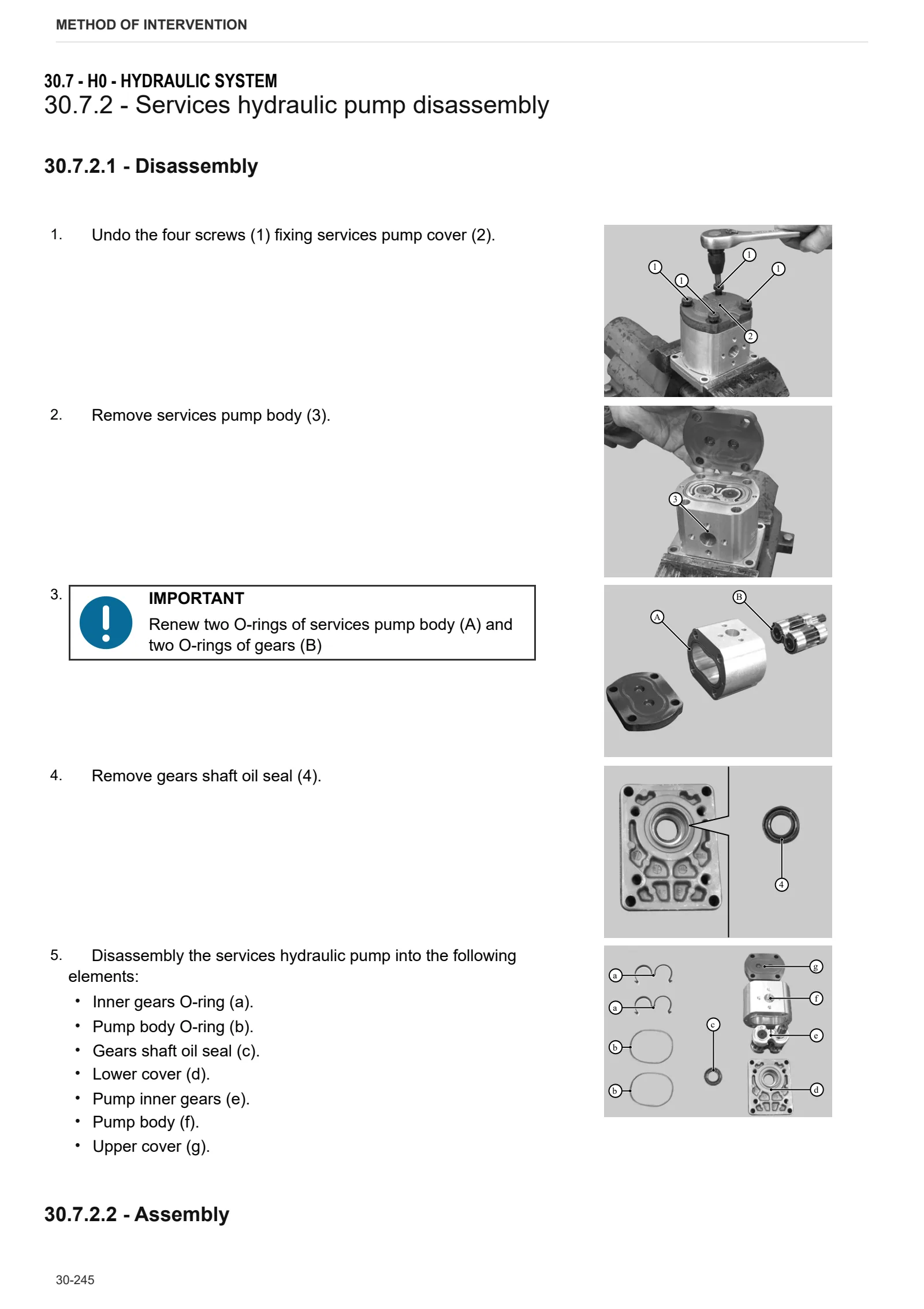
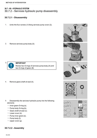
- Services hydraulic pump disassembly
- Lift hydraulic pump
- Steering pumps
- Steering pump disassembly
- Hydraulic circuit pressure holding valve
- Hydraulic circuit pressure holding valve disassembly
- Hydraulic circuit pressure holding valve calibration
L0 – Electrical system
- Battery
R0 – Rear lift
- Lift
- Lift and components disassembly
- Lift unit – piston seal renewal
- Lift control valve
- Lift control valve disassembly
T0 – Tracks
- Driving sprocket
- Front idler
- Track roller
- Track rollers
- Track tensioner cylinder
- Track roller frame
- Track roller frame alignment
- Track tensioner spring
- Tracks (chain)
- Tracks tensioning
V0 – Ballast – towing hitches
- Drawbar
Wiring diagrams
Introduction
- Structure of the unit
- Index of wiring looms and components
- Basic electronics for mechanics (1/2)
- Basic electronics for mechanics (2/2)
- Electrical and electronic components (1/2)
- Electrical and electronic components (2/2)
Components
- Components
Systems
- Radar ground points
- Starting and preheating
- Lights
- Work lights
- Instrument panel
- PTO
- Services – Brake lights
Wiring harnesses
- Battery wiring looms – positive terminal – 0.013.7647.4
- Positions of battery positive wiring connectors
- Battery wiring looms – negative terminal – 0.013.7647.4
- Positions of battery negative wiring connectors
- Front wiring loom – 0.013.7644.4/10
- Position of front wiring loom connectors
- Preheating wiring loom – 0.013.7649.4 – 0.013.7445.4
- Pre-heating wiring connector positions
- Electronic engine controller wiring – 0.013.7648.4
- Central wiring loom – 0.013.7645.4
- Position of central wiring loom connectors
- Handbrake wiring loom – 0.012.9759.4
- Position of handbrake wiring connectors
- Rear wiring loom – 0.013.7635.4
- Position of rear wiring loom connectors
- Worklights wiring for types with sun roof – 0.012.6688.4 – 0.012.6689.4/10
- Positions of worklight connectors for types with sun roof