Document overview
Digital Workshop Manual documentation for model HURLIMANN TTCD 6.1 L06 Stage4 from the Tractor components – Engine – DEUTZ AG Stage 4-5 family. Language: English; 558 pages.
The corresponding English table of contents contains 5 sections and 282 individual topics.
Main sections included
- Technical characteristics
- Method of intervention
Document details
- Brand: HURLIMANN
- Family: Tractor components – Engine – DEUTZ AG Stage 4-5
- Model: TTCD 6.1 L06 Stage4
- Document type: Workshop Manual
- Language: English
- Pages: 558
- File size: 129.72 MiB
- Format: Digital PDF download
Compatibility
Before purchasing, verify that your machine model and reference code match HURLIMANN TTCD 6.1 L06 Stage4.
Complete table of contents
Technical characteristics
Engine
- Technical data – Pressure/temperature transmitter
- Technical data – Pressure transducer
- Pressure transducer
- Technical data – Pressure transducer
- Pressure sensor
- Technical data – Pressure transducer
- Pressure transducer
- Technical data – Pressure sensor
- Technical data – Temperature transmitter
- Technical data – Temperature transmitter
- Technical data – Temperature transmitter
- Temperature sender
- Technical data – Temperature transmitter
- Technical data – Temperature transmitter
- Technical data – Speed indicator
- Technical data – Speed indicator
- Technical data – Speed indicator
- technical specifications – NOx sensor (24 V)
- technical specifications – NOx sensor (12 V)
Method of intervention
B0 – Engine
- Disassembling and assembling alternator (poly-V-belt, level 1)
- Disassembling and assembling crankcase breather
- Replacing the crankshaft O-ring (opposite end to flywheel)
- Disassembling/assembling crankshaft wear sleeve (side opposite flywheel)
- Disassembling and assembling the front cover (fixing elements)
- Assembly and disassembly of piston cooling nozzles
- Assembly and disassembly of piston cooling nozzles
- Checking the camshaft bearing
- Removing and refitting crankshaft bearing cap
- Blanking elements
- Blanking elements
- Blanking elements
- Blanking elements
- Oil dipstick
- Oil dipstick
- Pipe (crankcase breather)
- Disassembling and assembling the lubricant oil sump (pressed steel sump)
- Removing and fitting lubricant oil sump (heavy version)
- Removing and fitting lubricant oil sump (heavy version)
- Removing and fitting lubricant oil sump (heavy version)
- Oil filler neck
- Disassembling and assembling the torsional vibration damper
- Disassembling and assembling the torsional vibration damper
- Disassembling and assembling the torsional vibration damper
- Disassembling and assembling the flywheel (fixing elements)
- Replacing the starter motor ring gear on the flywheel
- Removing and fitting the crankshaft
- Check the crankshaft
- Check the endfloat of the crankshaft
- Assembly and disassembly of the crankshaft bearing
- Check the crankshaft bearings
- Disassembly and reassembly of connecting rod shank
- Check the connecting rod shank
- Disassembling and assembling the piston
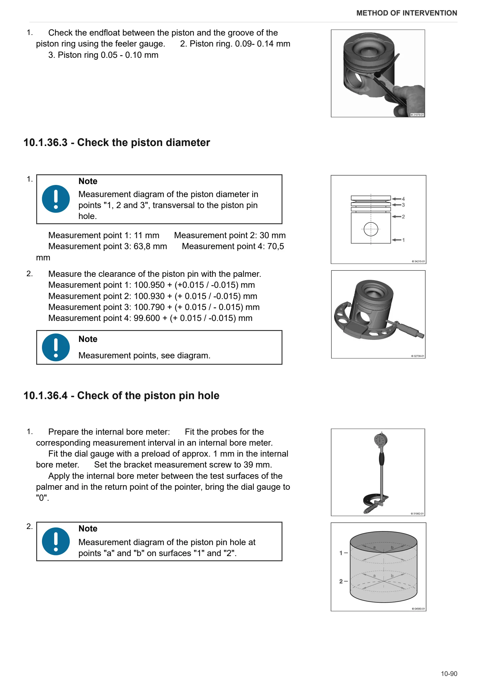
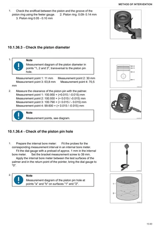
- Check the piston
- Check the piston
- Disassembling and assembling the piston rings
- Check the piston rings
- Check the piston rings
- Check the piston rings
- Compression test
- Disassembling and assembling the cylinder head cover
- Removing and fitting the cylinder head cover
- Disassembling and assembling the cylinder head (fasteners)
- Measuring piston protrusion
- Assembly and disassembly of the valves
- Checking valves, valve guides, valve springs and valve recess
- Replacing the injector bush
- Clean the injector bush
- Clean the injector bush seat
- Blanking elements (cylinder head)
- Eye-bolt for transporting (cylinder head)
- Eye-bolt for transporting (cylinder head)
- Replace the crankshaft O-ring (flywheel end)
- Disassembling and assembling the gearbox
- Assembly and disassembly of the camshaft
- Check the camshaft
- Checking and setting valve clearance (6 cylinder)
- Assembly and disassembly of the distribution valve
- Removing and refitting the valve timing system
- Disassembly and assembly of the control elements
- Disassembling and assembling the oil cooler
- Removing and fitting the lubricant oil radiator
- Removing and fitting the lubricant oil radiator
- Removing and fitting the lubricant oil radiator housing
- Disassembling and assembling the lubricant oil radiator (blanking elements)
- Removing and fitting the lubricant oil radiator housing (fastener elements)
- Blanking elements (lubricant oil cooler housing)
- Blanking elements (lubricant oil cooler housing)
- Coolant pipe (lubricant oil radiator housing – crankcase)
- Coolant pipe (Lubricant oil cooler – cylinder head)
- Disassembling and assembling the oil suction pipe
- Disassembly and assembly of the fuel control unit (fastening elements)
- Disassembly and completion of the fuel control unit
- Disassembling and completing assembly of the fuel control unit (2000 bar injection system)
- Disassembling and assembling the high pressure pump (fastener elements)
- Disassembling and assembling the injector (1600 bar injection system)
- Disassembling and assembling the injector (1600 bar injection system)
- Flexible hose connectors
- Connector plug (fuel delivery pump)
- Removing and refitting fuel lines (fuel delivery pump – pilot block)
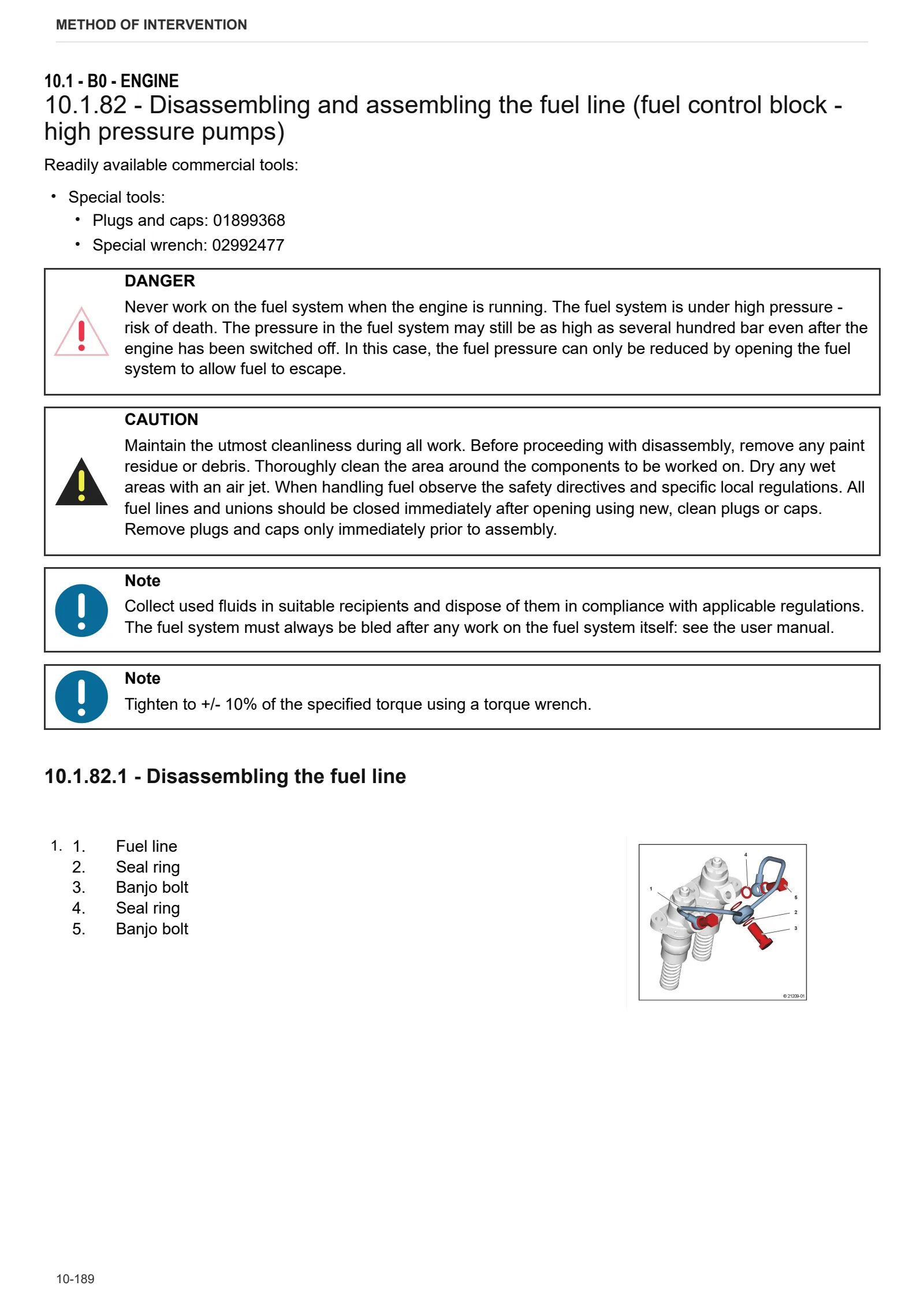
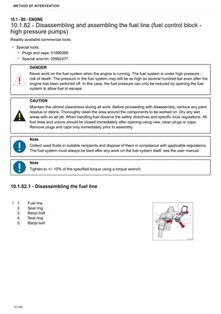
- Disassembling and assembling the fuel line (fuel control block – high pressure pumps)
- Disassembling and assembling the rail (1600 bar injection system)
- Disassembling and assembling the rail (1600 bar injection system)
- Disassembling and assembling the rail (2000 bar injection system)
- Disassembling and assembling the pressure cut-off valve (rail)
- Disassembling and assembling the pressure cut-off valve (rail)
- Disassembly and assembly of the rail pressure sensor
- Disassembly and assembly of the rail pressure sensor
- Removing and refitting fuel lines (Rail, cylinder head, fuel control unit – fuel filter)
- Fuel pipes (Fuel pump, fuel filter, pilot lock)
- Fuel pipes (Rail, cylinder head, pilot lock- fuel filter)
- Vibration damper (installation position)
- Disassembling and assembling charge air pipe
- Disassembling and assembling charge air pipe
- Removing and fitting the coolant pump
- Disassembling and assembling coolant pipe (ribbed V-belt, level 1)
- Removing and fitting the coolant pump (fastening elements)
- Removing and refitting adapter (coolant pump – thermostat housing)
- Transmission components (coolant pump)
- V-belt pulley
- Assembling and disassembling the thermostat
- Assembling and disassembling the thermostat
- Disassembling and assembling the thermostat
- Check the thermostat (after removing)
- Check the thermostat (after removing)
- Removal and installation of the thermostat housing
- Removal and installation of the thermostat housing
- Removal and installation of the thermostat housing
- Disassembling and assembling the thermostat housing (fastener elements)
- Blanking elements (coolant pump – thermostat housing)
- Blanking elements (thermostat housing)
- Blanking elements (thermostat housing)
- Blanking elements (thermostat housing)
- Blanking elements (thermostat housing)
- Blanking elements (thermostat housing)
- Flexible hose fastening (Thermostat housing)
- Flexible hose connector (thermostat box)
- Connection (compensation line)
- Breather pipe (thermostat box – cooler)
- Pipes (AGR radiator cylinder head)
- Compensation line (thermostat box)
- Removing and fitting belt tensioner (ribbed V belt)
- Disassembly and refitting of the belt tensioner (ribbed V-belt, level 1)
- Disassembly and refitting of the belt tensioner (ribbed V-belt, level 1)
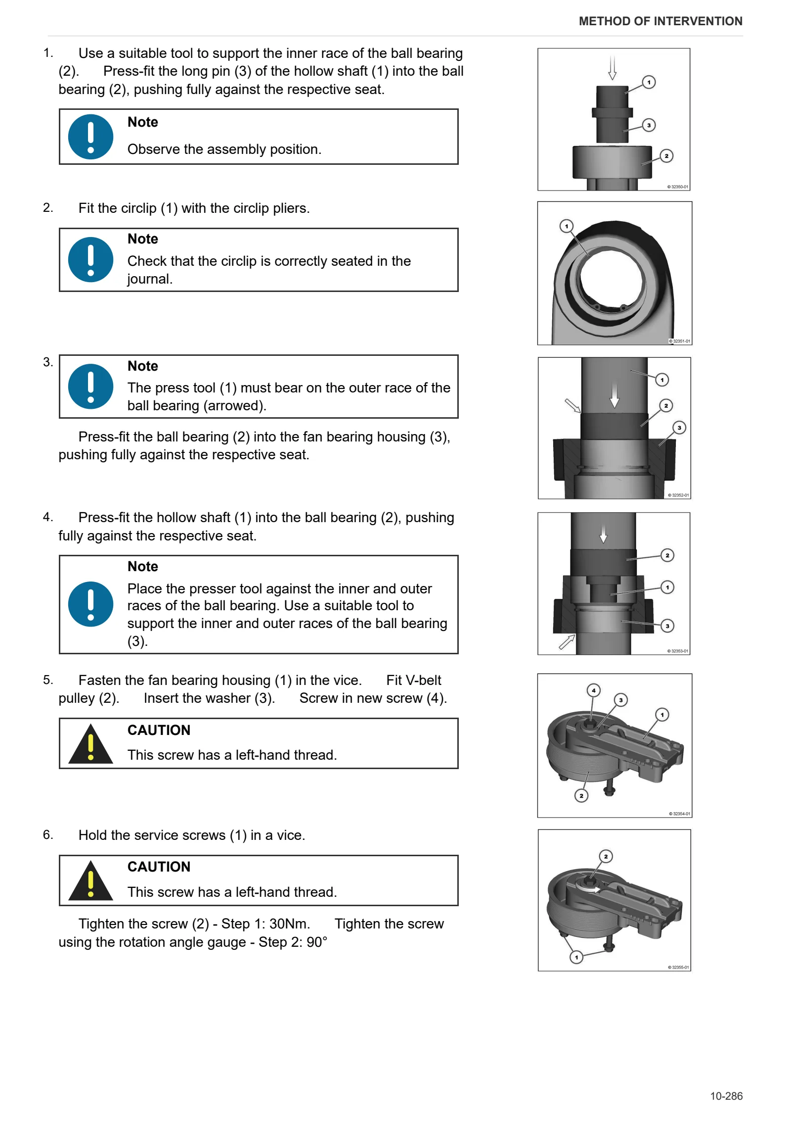
- Removal and assembly of the fan support
- Removal and assembly of the fan support
- Removal and assembly of the fan support
- Removal and assembly of the fan support
- Fastener elements (fan mount)
- Disassembling and assembling the exhaust manifold
- Disassembling and assembling the exhaust manifold
- Removal and installation of the exhaust pipe (auxiliaries)
- Disassembling and assembling the exhaust manifold
- Assembling and disassembling the console
- Disassembling and assembling the butterfly valve
- Disassembling and assembling the butterfly valves
- Disassembling and assembling the radiator
- Removing and fitting the exhaust gas recirculation (EGR) radiator
- Disassembling and assembling the regulator
- Disassembling and assembling the regulator
- Disassembling and assembling the Venturi pipe
- Disassembling and assembling the Venturi pipe
- Removing and fitting the pipes (cylinder head – radiator, radiator – cylinder head).
- Exhaust gas pipe (Venturi tubes – mixing tubes)
- Pipe (exhaust pipe – pressure transducer)
- Pipe (exhaust pipe – pressure transducer)
- Disassembling and assembling the turbocharger
- Disassembling and assembling the turbocharger
- Disassembling and assembling the turbocharger
- Disassembling and assembling the lubricating oil pipe (exhaust gas turbocharger)
- Disassembling and assembling the lubricating oil pipe (exhaust gas turbocharger)
- Removing and refitting the lubricant oil return pipe – (upper section) – (turbocharger)
- Removing and refitting the lubricant oil return pipe – (upper section) – (turbocharger)
- Disassembling and assembling the lubricating oil return pipe (turbocharger)
- Removing and refitting the lubricant oil return pipe – (lower section) – (turbocharger)
- Removing and refitting the lubricant oil return pipe – (lower section) – (turbocharger)
- Removing and refitting the lubricant oil return pipe – (lower section) – (turbocharger)
- Disassembling and assembling alternator (poly-V-belt, level 1)
- Disassembling and assembling alternator (poly-V-belt, level 1)
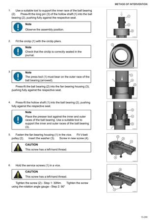
- Removing and fitting the V belt pulley/poly-V belt pulley (alternator)
- Disassembling and assembling the console (ribbed V-belt, level 1)
- Disassembling and assembling the console (ribbed V-belt, level 1)
- Disassembling and assembling the console (ribbed V-belt, level 1)
- Disassembling and assembling the console (ribbed V-belt, level 1)
- Fitting and removing the rotation device (PTOC)
- Fitting and removing the rotation device
- Disassembling and assembling the connector housing
- Cover (connector casing)
- Cover (connector casing)
- Cover (connector casing)
- Disassembling and assembling the heater
- Disassembling and assembling the heater
- Disassembling and assembling the heater
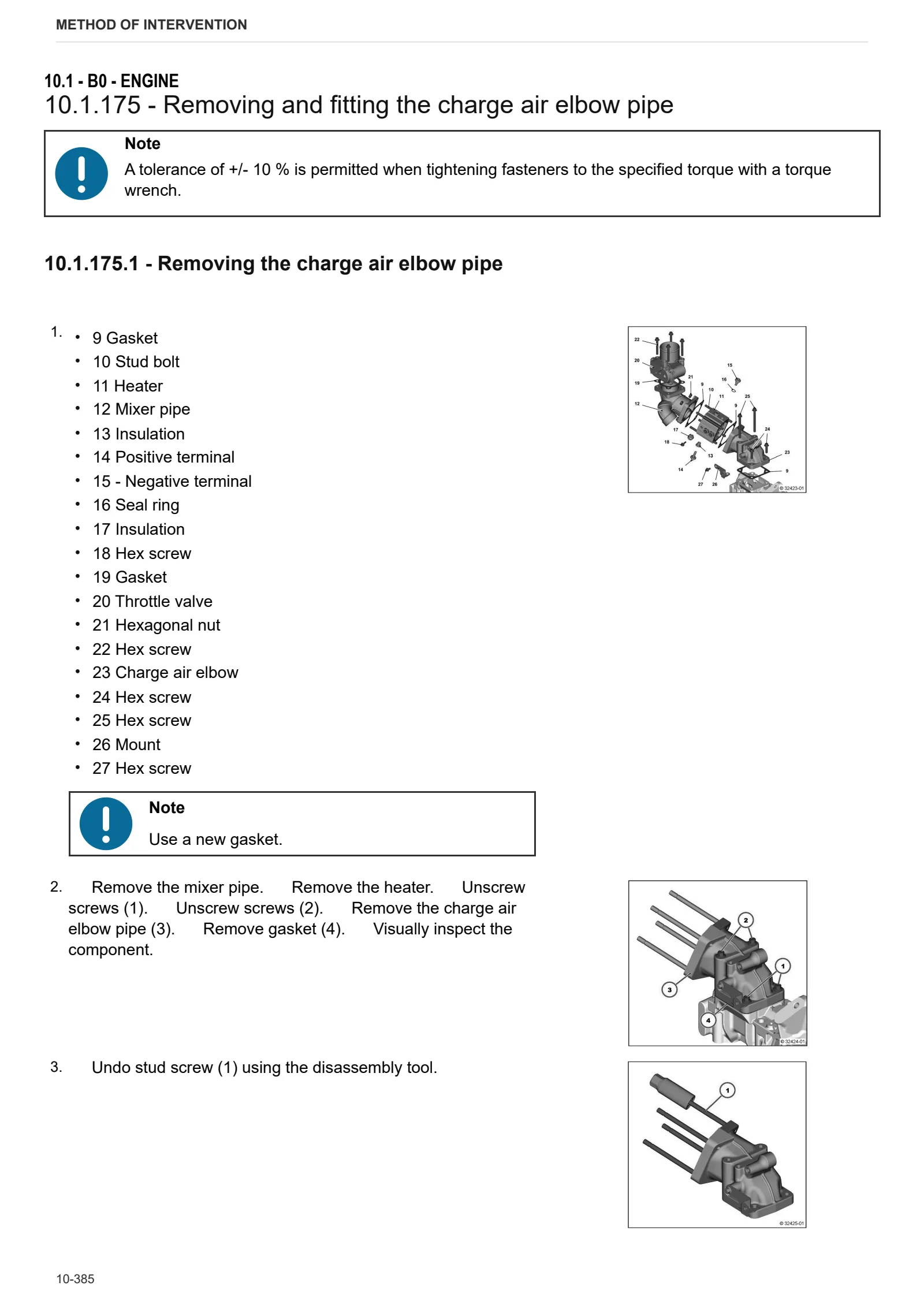
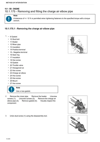
- Removing and fitting the charge air elbow pipe
- Disassembling and assembling the mixer pipe
- Disassembling and assembling the mixer pipe
- Disassembling and assembling the butterfly valve
- Disassembling and assembling the butterfly valve
- Disassembly and assembly of the flange
- Removing and refitting the diesel particulate filter
- Removing and fitting the diesel particulate filter (9.5 ” axial and radial system – removed)
- Disassembling and assembling the NOx sensor
- Pressure transducer (exhaust back-pressure).
- Fitting the SCR (Selective Catalytic Reduction) dosing unit
- Cleaning the SCR delivery pump (Selective Catalytic Reduction)
- Cleaning/Checking SCR (Selective Catalytic Reduction) metering unit
- Cleaning the SCR (Selective Catalytic Reduction) pipe (delivery pump – metering unit)
- Blanking elements (diesel oxidation catalytic converter/diesel particulate filter, SCR catalytic converter)
- Cover guard (Differential pressure transducer)
- Mount (Exhaust after-treatment system 9.5″)
- SCR (Selective Catalytic Reduction) urea solenoid valve
- SCR delivery pump (Selective Catalytic Reduction)
- Outlet module particulate filter
- Mixer pipe (threaded connection) SCR (Selective Catalytic Reduction)
- Mixer pipe (fastening element) SCR (Selective Catalytic Reduction)
- Blanking elements (crankcase, PTO-A)
- Closing elements (Power Take-Off PTO-B)
- Closing elements (Power Take-Off PTO-B)
- Blanking elements (gearbox, PTO-C)
- Blanking elements (gearbox, PTO-C)
C0 – Engine accessories
- Removing and fitting the fuel filter head
- Disassembling and assembling the fuel delivery pump (fastener elements)
- Fuel filter
- Manual fuel pump
- Filter holder
- Assembly of the pressure transducer (fuel pressure)
- Disassembly and refitting of the intake air pressure/temperature sender
- Blanking elements (mixer pipe, intake air)
- Shield plate (exhaust gas back-pressure sensor)
- Turbocharger shield plate
- Support plate (exhaust gas back-pressure relay – sensor)
- Support (shield plate)
- Pressure transducer (exhaust back-pressure).
- Pressure transducer (exhaust back-pressure).
- Connector manifold (intake air)
- Connector manifold (intake air)
- Intake manifold (exhaust gas turbocharger)
- Removing and fitting the fan mount (fastener elements)
- Removing and fitting the fan mount (fastener elements)
- Removing and fitting the temperature sender
- Removing and fitting the pressure transducer
- Mount (radiator – exhaust gas recirculation)
- Mount (radiator – exhaust gas recirculation)
- Pressure transducer/Duct (exhaust gas back-pressure).
- Pressure transducer/Duct (exhaust gas back-pressure).
- Disassembling and assembling the pressure transducer (exhaust back-pressure)
- Connection (Starter)
- Connection (Starter)
- Shield plate (starter)
- Alternator
- Starter (fasteners)
- Mount (Assembly foot, side opposite of the flywheel)
- Mount (assembly foot, side opposite of the flywheel)
- Mount (assembly foot, flywheel side)
- Disassembling and assembling the crankshaft speed sensor (fastener elements)
- Disassembling and assembling the crankshaft speed sensor (fasteners)
- Disassembling and assembling the crankshaft speed sensor (fasteners)
- Disassembling and assembling the camshaft speed sensor (ancillaries)
- Disassembly and refitting of the intake air pressure/temperature sender
- Fastener elements (wiring bundle)
- Fastener elements (wiring bundle)
- Fastener elements (wiring bundle)
- Support plate (on the charge air pipe)
- Support (wiring harness)
- Temperature sender (coolant)
- Fitting the pressure transducer (fuel pressure / lubricant oil pressure)
- Relay (heater, thermo-starter, glow plugs)
- Connector cable (relay – alternator)
- Connector cable (relay – heater)
- Protective cap (relay)
- Heater (connector line)
- Check the seal of the cooling system
- Differential pressure sender (diesel particulate filter)
- Differential pressure sender (diesel particulate filter)
- Temperature sender (upstream of the SCR catalytic converter)
- Temperature sender (ahead of and after diesel oxidation catalytic converter)
- Temperature sender (exhaust gas)
- Temperature sender (inlet air and ambient air temperature)
- V-Band clamp.
- VBand clamp (4″ exhaust pipe)
- VBand clamp (turbocharger)
- Mount (exhaust gas back-pressure sensor)