Document overview
Workshop Manual PDF for HURLIMANN TCD 2012 L06 4V DCR Stage 3A, Tractor components – Engine – DEUTZ AG Stage 3 family. Document language: English; 361 pages.
The corresponding English table of contents contains 13 sections and 99 individual topics.
Main sections included
- Introduction
- Technical characteristics
- Calibrations and electronic diagnosis
- Method of intervention
- Wiring diagrams
Document details
- Brand: HURLIMANN
- Family: Tractor components – Engine – DEUTZ AG Stage 3
- Model: TCD 2012 L06 4V DCR Stage 3A
- Document type: Workshop Manual
- Language: English
- Pages: 361
- File size: 24.89 MiB
- Format: Digital PDF download
Compatibility
Before purchasing, verify that your machine model and reference code match HURLIMANN TCD 2012 L06 4V DCR Stage 3A.
Complete table of contents
Introduction
- Introduction – Engines
- Tightening Torques
Technical characteristics
Engine
- Components of the TCD 2012 L04/L06 4V DCR engine
- Technical data of Engine TCD 2012 4V
- Tightening requirements TCD 2012 L04/L06 4V DCR (Lv.2) engine
- Tightening requirements TCD 2012 L04/L06 4V DCR (Lv.3) engine
Calibrations and electronic diagnosis
Diagnostic tools
Serdia 2000
- SERDIA 2000 level III” software
Diagnostic tool screens
- Engine control unit – Deutz EMR3
Method of intervention
- Tools for engine disassembly and reassembly
- Workshop tools for engine disassembly and reassembly
B0 – Engine
- Removing and installing the crankcase bleeding
- Removing and installing torsional vibration damper
- Alternator, fuel pump, coolant pump and fan drivebelt
- Removing and installing the flywheel
- Removing and installing the belt tensioner (V-rib belt)
- Air conditioning compressor drivebelt
- Air conditioning compressor drivebelt tensioning
- Checking piston overhang
- Removing and installing the rocker arm housing
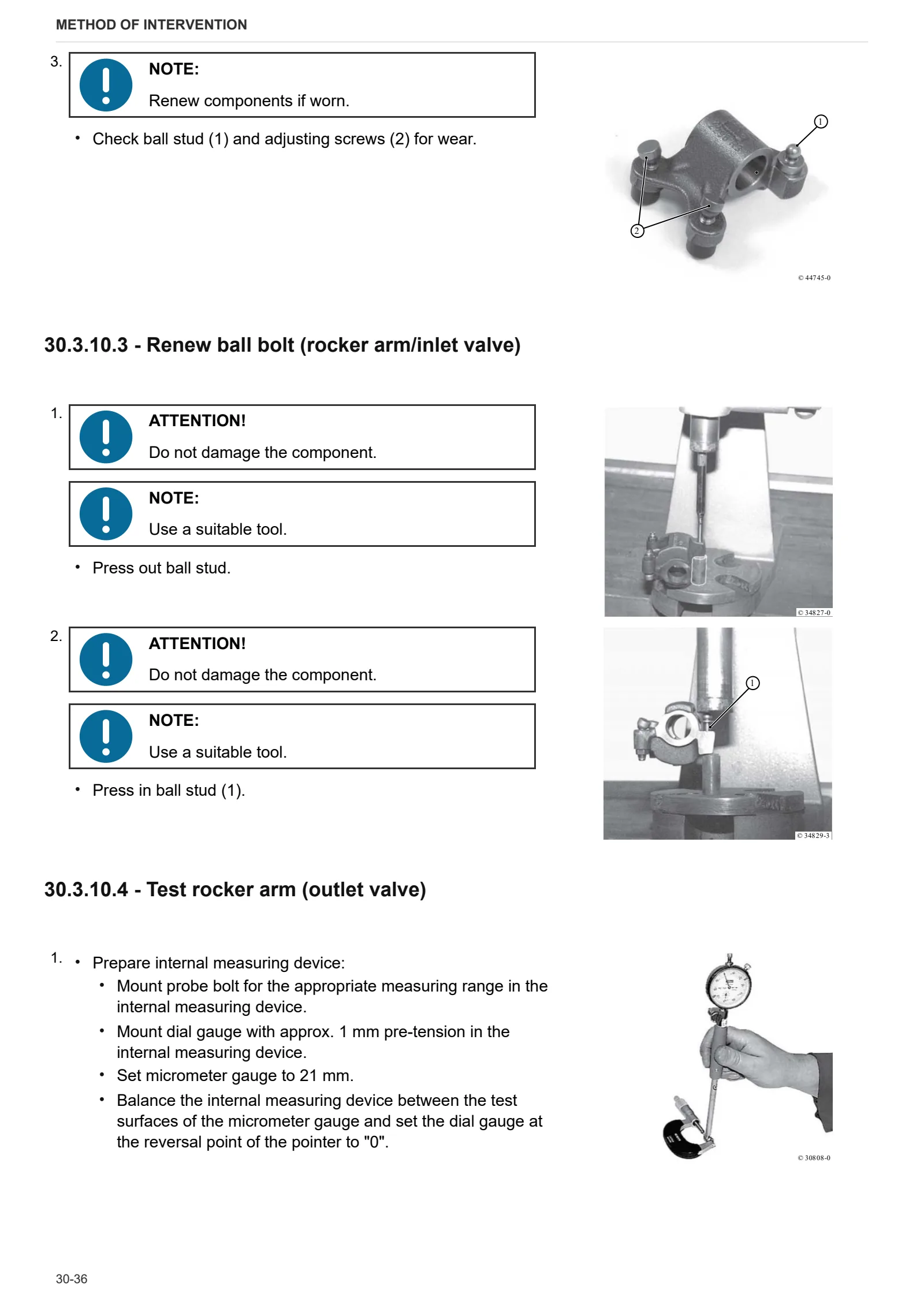
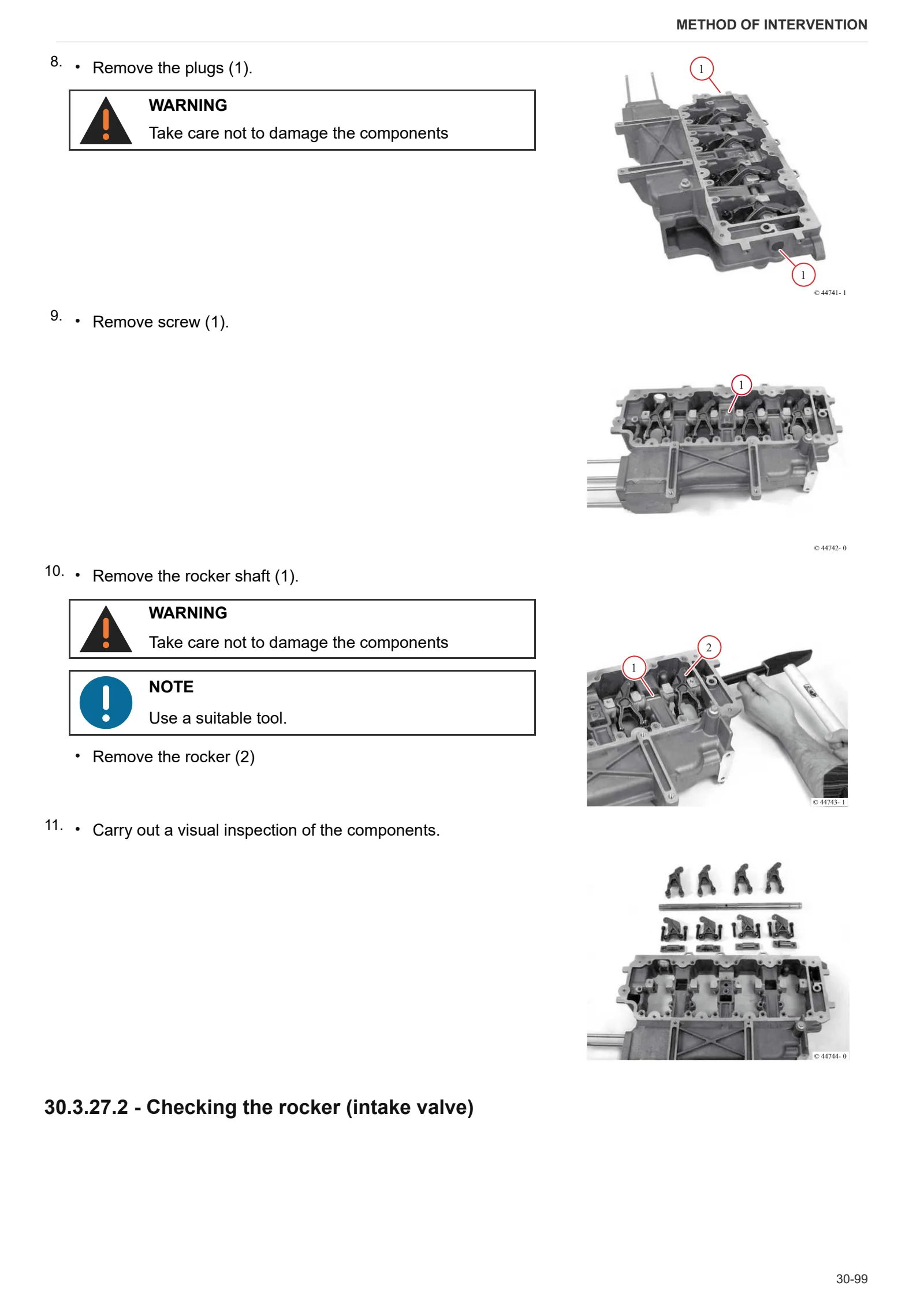
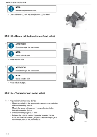
- Disassembling, assembling and checking the rocker arm and rocker arm bracket
- Checking and setting the valve clearance
- Changing the engine oil
- Checking that the radiator is clean
- Removing and installing the cooler (exhaust gas recirculation)
- Removing and installing the flutter valve (exhaust gas return)
- Checking the coolant thermostat when uninstalled
- Removing and installing the fan drive
- Removing and installing the actuator (exhaust gas return)
- Removing and installing the exhaust line
- Removing and installing the shutoff valve (exhaust gas recirculation)
- Compression test
- Setting the shut-off valve (exhaust return)
- Removing and installing the turbocharger
- Assembly and disassembly of the engine on the assembly stand
- Adjustment of valve clearance
- Fitting and removing rocker seat
- Removing and refitting rocker seat, checking
- Disassembly and assembly of the cylinder head
- Measuring piston protrusion
- Valve assembly and disassembly
- Valve check
- Check the valve guide
- Check the valve residual
- Test data and settings
- Check the endfloat of the crankshaft
- Check the crankshaft
- Replace the crankshaft O-ring (flywheel end)
- Replacing the crankshaft O-ring (opposite end to flywheel)
- Check the connecting rod drum
- Assembly and disassembly of the crankshaft
- Disassembly and assembly of the piston and connecting rod drum
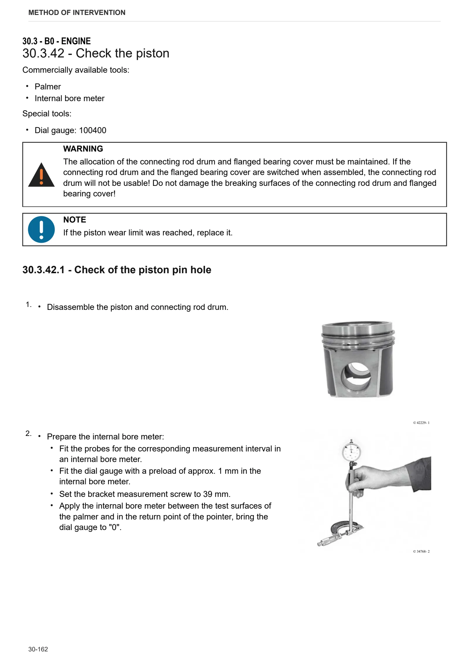
- Check the piston
- Check the piston rings and piston grooves
- Assembly and disassembly of piston cooling nozzles
- Removal and refitting of the crankcase breather
- Check the cylinder
- Removal and refitting of the front cover (opposite end to flywheel)
- Disassembly and assembly of the gear case cover
- Assembly and disassembly of the camshaft
- Check the camshaft
- Removal and refitting of the rotation device
- Removal and refitting of the heater
- Removal and refitting of the turbocharger
- Removing and fitting the butterfly valve (exhaust gas recovery)
- Removing and fitting the cooler (exhaust gas recovery)
- Removing and fitting regulator unit (exhaust gas recovery)
- Removing and fitting the cutoff valve (exhaust gas recovery)
- Adjusting the cutoff valve (exhaust gas recovery)
- Removing and fitting the fuel delivery pump (driven by ribbed V-belt) (L3)
- Removal and refitting of the fuel control unit
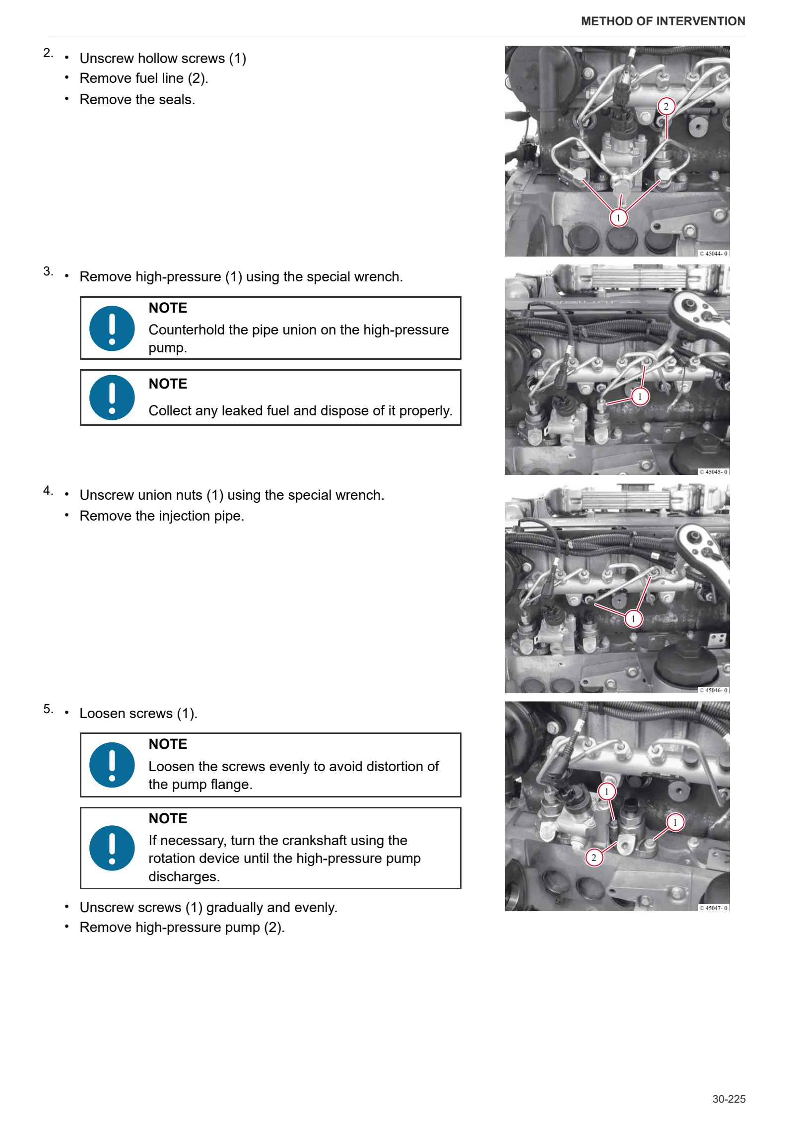
- Removal and refitting of the high-pressure pump (installation position A)
- Removal and refitting of the high-pressure pump (installation position B)
- Removal and refitting of the common rail
- Removal and refitting of the injectors
- Removal and refitting of the pressure cut-off valve
- Removal and refitting of the oil sump pan.
- Removal and refitting of the oil pickup pipe
- Removal and refitting of the oil cooler
- Removal and refitting of the lube oil cooler housing
- Removal and refitting of the water pump
- Testing the thermostat (after removal)
- Removal and refitting of the fan drive system
- Removal and refitting of the fan drive system
- Removal and refitting of the torsional vibration damper
- Removing and fitting belt tensioner (ribbed V-belt)
- Removal and refitting of the flywheel
C0 – Engine accessories
- Disassembly and assembly of the speed indicator (crankshaft)
- Removal and refitting of the camshaft speed sensor
- Removal and refitting of the exhaust manifold
- Removal and refitting of the fuel filter head.
- Removal and refitting of the rail pressure sensor
- Removing and fitting the alternator (driven by ribbed V-belt) (L3)
- Disassembly and assembly of the starter
- Removal and refitting of the supply air pressure/temperature sender
- Remove and install the heating flange
- Removing and installing the fuel supply pump
Wiring diagrams
Introduction
- Introduction
Wiring harnesses
- Engine wiring loom – 0421.4410 – 0421.3523
- Engine wiring loom – 0421.5284