Document overview
Workshop Manual for HURLIMANN PRINCE 60 → ZKDFV10200MH50001 from the PRINCE (STAGE 5) family. Digital PDF in English with 1,436 pages.
The corresponding English table of contents contains 49 sections and 451 individual topics.
Main sections included
- Introduction
- Safety
- Technical characteristics
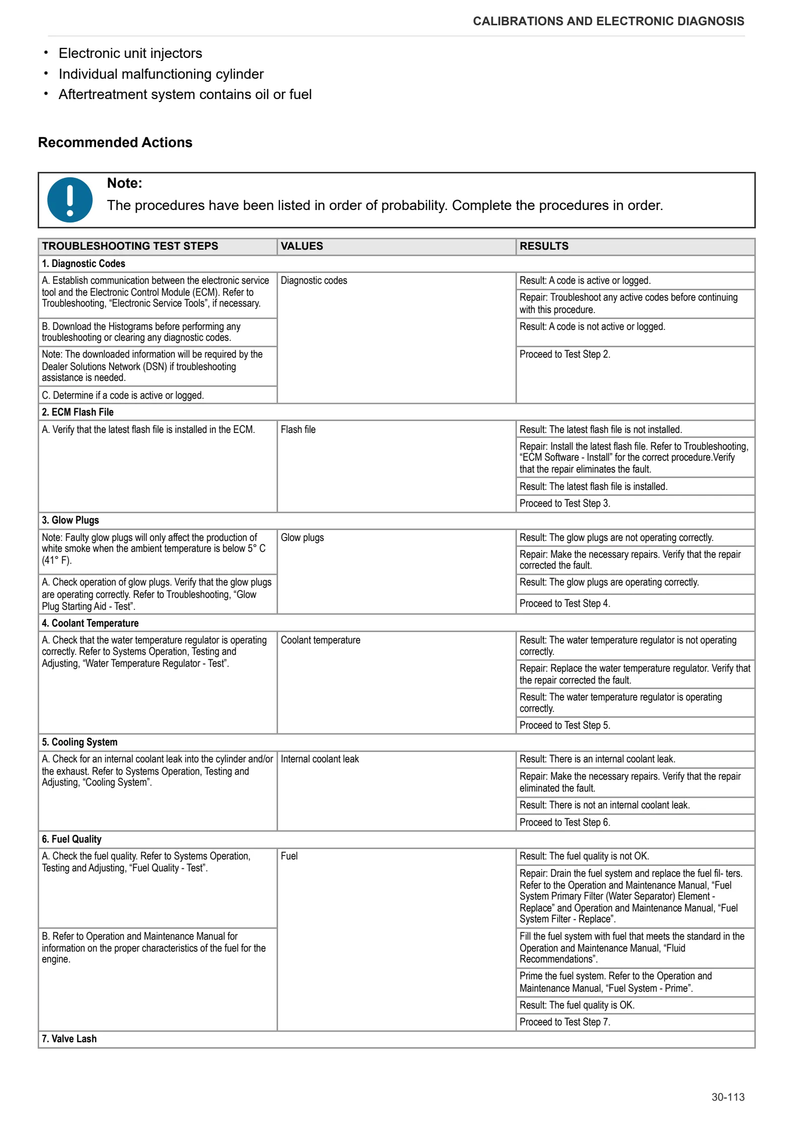
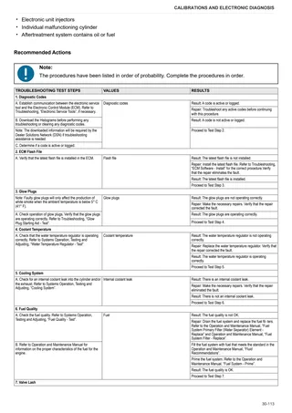
- Calibrations and electronic diagnosis
- Method of intervention
- Wiring diagrams
- Service Info
Document details
- Brand: HURLIMANN
- Family: PRINCE (STAGE 5)
- Model: PRINCE 60
- Starting serial number: ZKDFV10200MH50001
- Document type: Workshop Manual
- Language: English
- Pages: 1,436
- File size: 454.50 MiB
- Format: Digital PDF download
Compatibility
Before purchasing, verify that your machine model and reference code match HURLIMANN PRINCE 60 → ZKDFV10200MH50001.
Complete table of contents
Introduction
- Tightening torques
- Pump tightening torques
- Wheel nut/screw tightening torques
- Tightening torques for nuts and bolts of electrical connections
- Installation of solenoid valves and cartridge valves
- Installation of quick couplers
- Units of measurement and conversion factors
- One-way valves
- Fixing the steering wheel
- Spool valves
Safety
Preface
- Important notes concerning safety
Important safety information
- Recognising hazards
- Indications for persons in contact with the tractor
Safety rules
- Risks during tractor preparation
- Risks during maintenance
- Work on machine systems
- Special disassembly/assembly/inspection procedures
Safety pictograms
- Replacing safety pictograms
Environmental risks
- Hazards associated with the operating environment
Technical characteristics
Engine
- Important Safety Information
- General information
- Glossary of Electronic Control Terms
- Air Inlet and Exhaust System
- Lubrication System
- Cooling System
- Basic Engine
- Engine Design
- Fuel Injection Lines
- Fuel Injection Pump
- Fuel Injectors
- Fuel Filter Base (Secondary Fuel Filter Base)
- Fuel Manifold (Rail)
- Lifter Group
- Rocker Shaft
- Valve Mechanism Cover
- Valve Mechanism Cover
- Cylinder Head Valves
- Cylinder head
- Turbocharger
- Exhaust Gas Valve (NRS) (Throttle Valve)
- Exhaust Gas Valve (NRS)
- Exhaust Cooler (NRS)
- Inlet Manifold
- Inlet Manifold
- Exhaust Manifold
- Exhaust Manifold
- Camshaft
- Engine Oil Lines
- Engine Oil Relief Valve
- Engine Oil Pump
- Engine Oil Pan
- Engine Oil Pan (Engines With a Balancer)
- Crankcase Breather
- Water Temperature Regulator
- Cylinder Block
- Crankshaft
- Connecting Rod Bearing Journal
- Main Bearing Journal
- Connecting Rod
- Piston and Rings
- Balancer
- Housing (Front)
- Flywheel
- Flywheel Housing
- Crankshaft Pulley
- Belt Tension Chart
- Fan Drive
- Engine Lifting Bracket
- Alternator and Regulator
- Coolant Temperature Sensor
- Engine Oil Pressure Switch
- Inlet Manifold Temperature Sensor
- Inlet Manifold Temperature and Pressure Sensor
- Speed/Timing Sensor
- Glow Plugs
Engine accessories
- Electronic Control System Components
- Cleanliness of Fuel System Components
- Fuel System
- Clean Emissions Module
- Engine Electrical System
- Electric Starting Motor
- Temperature Sensor (DPF Inlet)
- Temperature Sensor (DOC Inlet)
Transmission
- Transmission
- Rear PTO and belly PTO
Rear axle
- Brakes and rear axle assembly
Front axle
- Front axle
Bodywork – Cab – Platform
- Main technical data
- External views of tractor with roll over protection frame
- Front views of tractor with cab
- Internal views of ROPS/cab
- Dimensions and weights of the tractor
- Dashboard
- Instrument cluster
- Right-hand console
- Driver’s seat
- Roof panel
- Air conditioning system
- Air conditioning system – Charging
Hydraulic system
- Steering-transmission hydraulic circuit, base version
- Steering-transmission hydraulic circuit, optional version
- Gear pump
- Differential lock control assembly
- Power steering valve
- Remote control valve
- Hydraulic lift control valve
Calibrations and electronic diagnosis
Diagnostic tools
- D-Tech and diagnostic ports
- D-TECH App
Commissioning and calibrating the tractor
- Commissioning procedure (EOL)
- Cluster configuration
- Measurement unit
- Wheel parameters
- Fuel System (Testing and Adjusting)
- Air Inlet and Exhaust System (Testing and Adjusting)
- Lubrication System (Testing and Adjusting)
- Cooling System (Testing and Adjusting)
- Basic Engine (Testing and Adjusting)
ECU alarms
- SDF Severity of alarms
- ECU ALARMS
Engine alarms
- ECU Perkins
- M142:Calibration memory – Erratic, intermittent or incorrect
- Component Location
- Troubleshooting list
- Troubleshooting 01
- Troubleshooting 02
- Troubleshooting 03
- Troubleshooting 04
- Troubleshooting 05
- Troubleshooting 06
- Troubleshooting 07
- Troubleshooting 08
- Troubleshooting 09
- Troubleshooting 10
- Troubleshooting 11
- Troubleshooting 12
- Troubleshooting 13
- Troubleshooting 14
- Troubleshooting 15
- Troubleshooting 16
- Troubleshooting 17
- Troubleshooting 18
- Troubleshooting 19
Software management
- ECUs
Method of intervention
- Special tools
B0 – Engine
- Complete engine
- Separating engine from transmission
- Separating the engine and transmission (cab version)
- Auxiliary utilities belt
- Alternator and ancillaries belt (version with air conditioning)
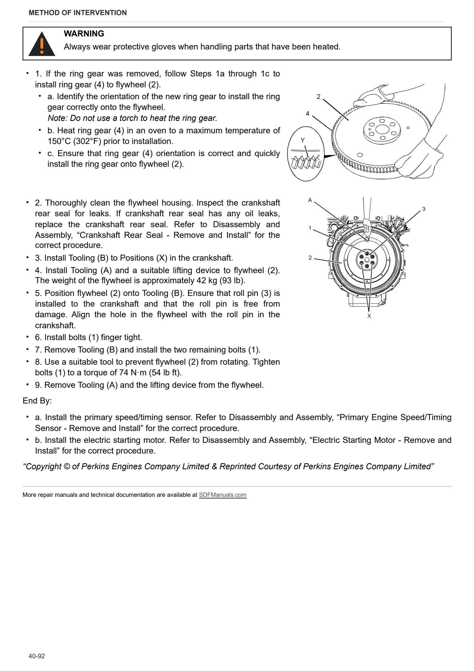
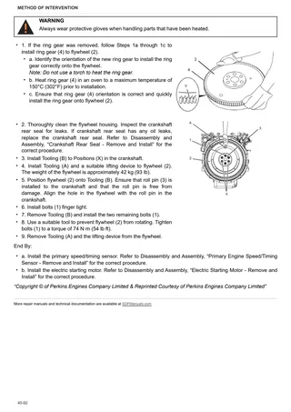
- Engine flywheel
- Fuel Filter Base – Remove and Install (Secondary Fuel Filter)
- Fuel Manifold (Rail) – Remove and Install (4 Cylinder Engines)
- Fuel Injection Lines – Remove and Install (4 Cylinder Engines)
- Exhaust Cooler (NRS) – Remove and Install (4 Cylinder Engines)
- Throttle Valve (Intake Air) – Remove
- Throttle Valve (Intake Air) – Install
- Fuel Injection Pump – Remove
- Fuel Injection Pump – Install
- Fuel Injection Pump Gear – Remove
- Fuel Injection Pump Gear – Install
- Fuel Injector – Remove and Install
- Turbocharger – Remove (4 Cylinder Engines)
- Turbocharger – Install (4 Cylinder Engines)
- Exhaust Gas Recirculation Valve – Remove and Install
- Exhaust Manifold – Remove and Install (4 Cylinder Engines)
- Exhaust Elbow – Remove and Install (Exhaust Elbow between the Turbocharger and the Clean Emissions Module (CEM))
- Support and Mounting (CEM) – Remove and Install
- Inlet Manifold – Remove and Install (4 Cylinder Engines)
- Inlet and Exhaust Valve Springs – Remove and Install
- Inlet and Exhaust Valves – Remove and Install
- Engine Oil Line – Remove and Install
- Engine Oil Cooler – Remove and Install
- Engine Oil Relief Valve – Remove and Install
- Engine Oil Pump – Remove
- Engine Oil Pump – Install
- Engine Lifting Bracket – Remove and Install
- Flywheel – Remove and Install
- Crankshaft Rear Seal – Remove and Install (Engines Without a Back Plate)
- Crankshaft Rear Seal – Remove and Install
- Crankshaft Wear Sleeve (Rear) – Remove and Install
- Flywheel Housing – Remove and Install
- Crankshaft Pulley – Remove and Install
- Crankshaft Pulley – Remove and Install (Multi VBelt)
- Crankshaft Front Seal – Remove and Install
- Housing (Front) – Remove
- Housing (Front) – Install
- Crankcase Breather – Remove and Install (404JE22T and 404J-E22TA)
- Valve Mechanism Cover – Remove and Install (404JE22T and 404J-E22TA)
- Rocker Shaft and Pushrod – Remove
- Rocker Shaft – Disassemble
- Rocker Shaft – Assemble
- Rocker Shaft and Pushrod – Install
- Cylinder Head – Remove (4 Cylinder Engines)
- Cylinder Head – Install (404J-E22T and 404JE22TA)
- Lifter Group – Remove and Install
- Camshaft – Remove
- Camshaft – Disassemble
- Camshaft – Assemble
- Camshaft – Install
- Engine Oil Pan – Remove and Install (Steel Engine Oil Pan only)
- Engine Oil Pan – Remove and Install (Cast Iron Engine Oil Pan only)
- Balancer – Remove and Install
- Pistons and Connecting Rods – Remove
- Pistons and Connecting Rods – Disassemble
- Pistons and Connecting Rods – Assemble
- Pistons and Connecting Rods – Install
- Connecting Rod Bearings – Remove (Connecting rods in position)
- Connecting Rod Bearings – Install (Connecting rods in position)
- Crankshaft Main Bearings – Remove
- Crankshaft Main Bearings – Install
- Crankshaft – Remove
- Crankshaft – Install
- Crankshaft Gear – Remove and Install
- Bearing Clearance – Check
- Glow Plugs – Remove and Install
- V-Belts – Remove and Install
- Alternator Belt – Remove and Install (Flat-Belt)
C0 – Engine accessories
- Replacing the coolant
- Bleeding the fuel circuit
- Engine fan
- Water radiator
- Compensation tank
- Air filter
- Fuel tank (platform version)
- Fuel tank (cab version)
- Fuel tank float sensor
- Fuel prefilter
- Fuel filter
- Starter motor
- DPF silencer unit (cab version)
- Fitting the DPF filter
- Exhaust pipe
- Clean Emissions Module – Remove and Install
- Water Pump – Remove and Install
- Water Temperature Regulator Housing – Remove and Install
- Water Temperature Regulator Housing – Remove and Install
- Primary Engine Speed/Timing Sensor – Remove and Install
- Secondary Engine Speed/Timing Sensor – Remove and Install
- Coolant Temperature Sensor – Remove and Install
- Engine Oil Pressure Sensor – Remove and Install (4 Cylinder Engines Only)
- Fuel Temperature Sensor – Remove and Install
- Temperature Sensor (Exhaust) – Remove and Install (Temperature Sensor For Diesel Oxidation Catalyst (DOC) and Diesel Particulate Filter (DPF))
- Pressure Sensor (DPF) – Remove and Install (Differential Pressure Sensor and Tube Assemblies)
- Pressure Sensor (DPF) – Remove and Install (Differential Pressure Sensor and Tube Assemblies)
- Boost Pressure Sensor – Remove and Install
- Inlet Manifold Temperature Sensor – Remove and Install
- Electronic Control Module – Remove and Install (Mounted Off Engine)
- Alternator – Remove and Install (V-Belt)
- Alternator – Remove and Install (Flat-Belt)
- Electric Starting Motor – Remove and Install
D0 – Transmission
- Changing the transmission oil
- Disassembling the input shaft (version without supercreeper gear)
- Gearbox input shaft – replacing oil seal (version with supercreeper)
- Disassembly of the main shaft
- Disassembling the secondary shaft
- Range reduction gearbox shaft
- Connector housing
- Separating front gearbox housing from rear gearbox housing (version without supercreeper)
- Gearbox and shuttle assembly – complete assembly (version without supercreeper)
- Separating front gearbox housing from rear gearbox housing (version with supercreeper)
- Disassembling gearbox assembly (version with supercreeper)
- Separating the gearbox casing from the rear gearbox casing
- Pressure plate assembly and clutch plates
- Checking clutch plate wear
- Thrust bearings
- Clutch release forks
- Bevel gear set and rear pinion
- Adjusting the bevel gear set and rear pinion
- 4WD and groundspeed PTO output shaft
- PTO output shaft
- PTO flange shaft
- Adjusting the parking brake
E0 – Rear axle
- Right-hand rear axle
- Left-hand rear axle
- Removing right/left hand rear axle
- Rear differential
- Removing rear differential
- Rear axle brake discs
F0 – Front axle
- 4WD shaft
- Support with front axle
- Carrier with front axle (cab version)
- Front axle
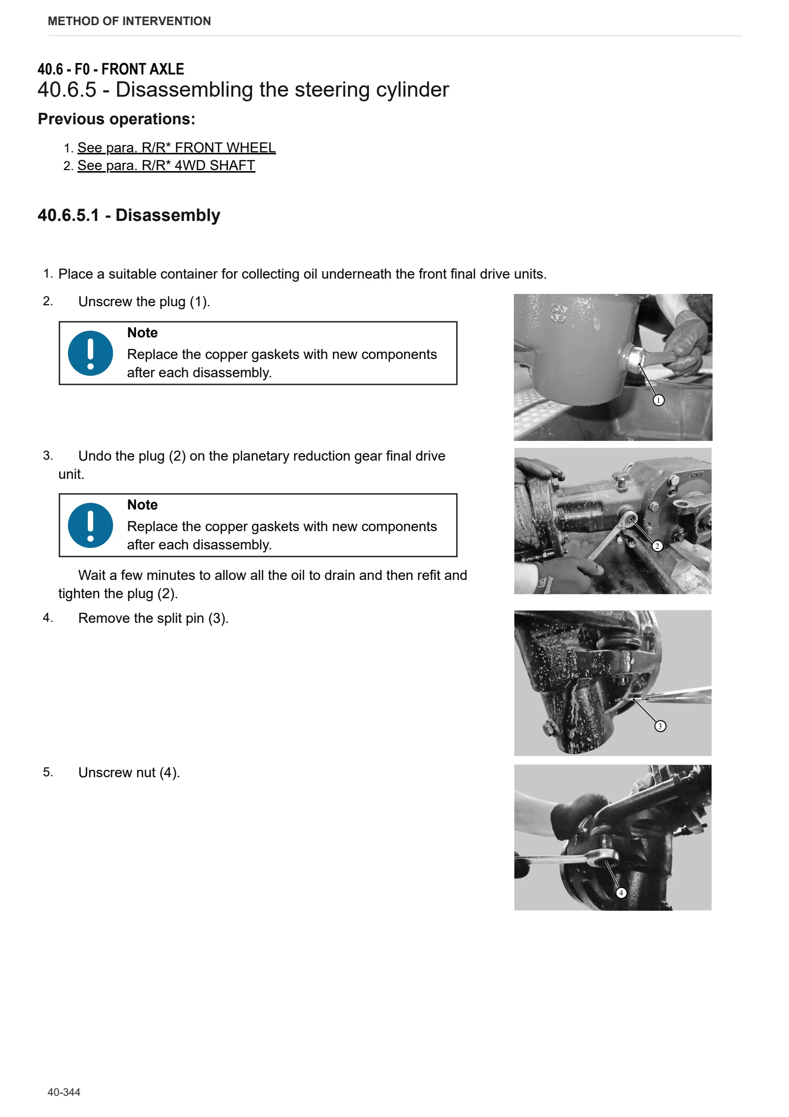
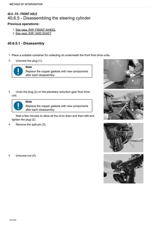
- Disassembling the steering cylinder
- Pinion-differential assembly
- Removing bevel gear set
- Adjustment of the bevel gear set
- Front axle shaft
- Planetary reduction gearbox
- Disassembling the planetary reduction unit
- Hydraulic pump drive
- Front final drive reduction unit adjustment
G0 – Bodywork – Cab – Platform
- Cab
- Platform
- Engine cowl and lateral cowl panels (platform version)
- Engine cowl (cab version)
- Footboard guards
- Roll bar
- Cab mat
- Sun blind
- Right hand console
- Adjustment of the lift control valve levers
- Dashboard (platform version)
- Dashboard (cab version)
- Instrument panel (platform version)
- Instrument panel (cab version)
- Lower dashboard (platform version)
- Cab headliner
- Cabin filter
- Discharging and charging the air conditioning system
- Air conditioning condenser
- Complete AC unit
- Dehydrator filter
- Air conditioning compressor
- Rear view mirrors (cab version)
- Seat (platform version)
- Seat (cab version)
- Right hand console (cab version)
- Brake and clutch pedals
- Parking brake (platform version)
- Parking brake lever (cab version)
- Steering wheel (platform version)
- Steering wheel (cab version)
- Steering column
- Adjusting brake pedal travel
- Adjusting the rear PTO clutch lever
- Clutch pedal adjustment
- Adjusting gear lever
H0 – Hydraulic system
- Hydraulic steering and auxiliary utilities pump
- Hydrostatic steering (orbitrol)
- Calibrating the distributor pressure relief valve
- Rear ancillary distributor
- Disassembling the rear ancillary utility distributor
- Double/single acting conversion device
L0 – Electrical system
- Alternator
- Work lights
- Steering column stalk
M0 – Front PTO
- Front PTO
- Disassembling the front PTO clutch
- Front PTO stub shaft
- Front PTO solenoid valve
N0 – Front lift
- Front lift assembly
- Front lift cylinder
R0 – Rear lift
- Rear lift
- Disassembling the rear lift
- Adjustment of the rear lift
- Sensing device mount
- Adjusting the sensing device tie-rod
- Disassembling the lift cylinder
- Rear lift bush
- Lift control distributor
- Disassembling the lift control distributor
- 3-point linkage
S0 – Wheels
- Front Wheels
- Rear wheels
V0 – Ballast – towing hitches
- Rear towing hitch and carrier
Wiring diagrams
Components
- Engine control unit
- A – Starting and charging
- B – Fuses
- C – Grounds
- D – Intermediate connections
- E – On-board instruments
- F – External lights (rotating beacon)
- G – Interior lights
- H – Manual electrical controls (steering column stalk)
- I – Circuit breakers
- J – Relays
- K – Sensors and transmitters
- L – Electromagnets and solenoid valves
- M – Electrical/electronic devices, Flasher units and Timers
- N – Electric motors and actuators
- O – Resistors and rheostats
- P – Various services
- R – Diagnostics
Systems
- S001 – Power
- S002 – Starter
- S003 – Engine control
- S004 – Front lights / horn
- S005A – Rear lights (platform version)
- S005B – Rear lights (cab version)
- S006A – Turn indicators / hazard warning lights (platform version)
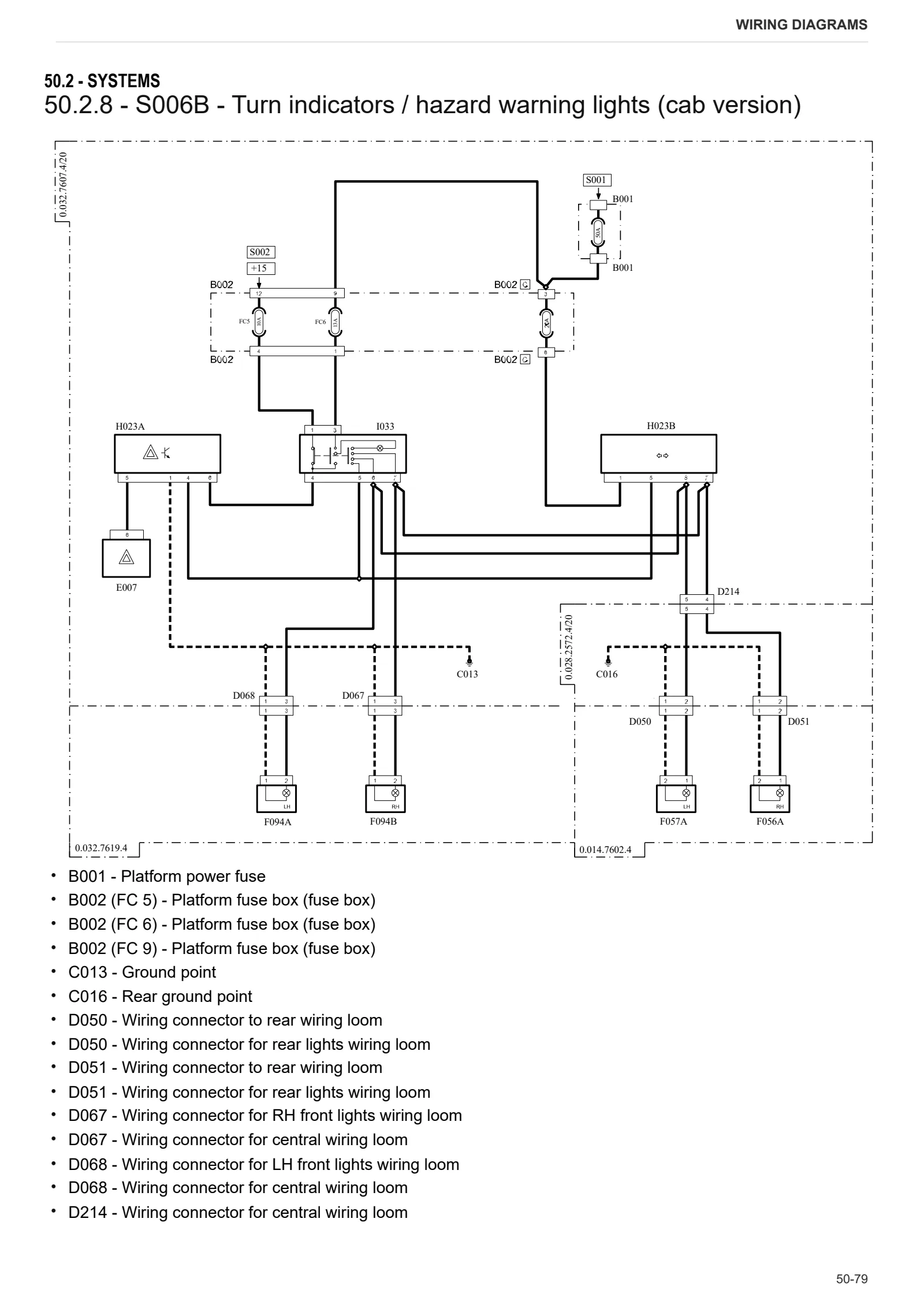
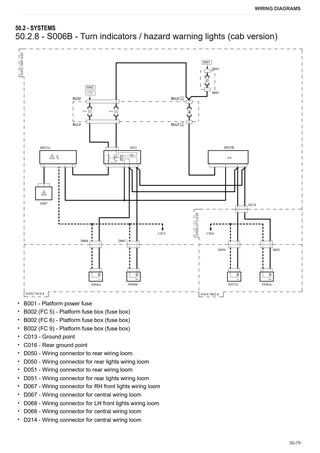
- S006B – Turn indicators / hazard warning lights (cab version)
- S007A – Work lights / rotating beacon (platform version)
- S007B – Work lights / rotating beacon (cab version)
- S008 – Front wiper (cab version)
- S009 – Rear wiper (cab version)
- S010 – Air conditioner (cab version)
- S011 – Internal lighting / radio / clock (cab version)
- S012 – Instrument cluster / indicators
- S013 – Power take off (PTO)
- S014 – Brake system
- S015 – Trailer socket
- S016 – Differential / 4WD
Wiring harnesses
- Wire colour reference table
- 0.007.6724.3/20 – Number plate light (platform version)
- 0.008.0361.3 – Work light
- 0.010.4795.3/10 – Distributor solenoid valve
- 0.013.2605.4 – Rotating beacon (platform version)
- 0.014.7593.4/20 – Cab
- 0.014.7595.4/10 – Cab lights
- 0.014.7596.4 – Air conditioner
- 0.014.7597.4 – Rotating beacon (cab version)
- 0.014.7598.4/10 – Windscreen wiper
- 0.014.7600.4 – Radio and ceiling light unit
- 0.014.7602.4 – Rear lights (cab version)
- 0.015.0031.4 – Ground cable for platform – cab interconnection
- 0.015.0070.4 – Solenoid valves
- 0.018.3547.4 – Seat wiring
- 0.028.2565.4 – Distributors
- 0.028.2572.4/20 – Rear wiring loom
- 0.028.2575.4 – Front PTO
- 0.032.7605.4/40 – Front wiring loom
- 0.032.7606.4/10 – Battery wiring
- 0.032.7607.4/20 – Central wiring loom
- 0.032.7609.4/20 – Cab power supply
- 0.032.7619.4 – Front lights
- 0.032.7620.4/20 – Cowl
- 0.900.7697.8 – Engine
Service Info
A0 – TRACTOR
- Diagnostics 2026 subscription
- After-sales 2026 subscription
- SERVICE NEWS RESEARCH GUIDE
- Diagnostics 2025 subscription
- After-sales 2025 subscription
- Diagnostics 2023 subscription
- Diagnostics 2024 subscription
- Diagnostics 2022 subscription
- Diagnostics 2021 subscription
- After-sales 2024 subscription
- After-sales 2023 subscription
- After-sales 2022 subscription
- After-sales 2021 subscription
- Diagnostics – 2020 subscription
- After-sales – 2020 subscription
B0 – ENGINE
- SERVICE NEWS – Electrical Fuel pump not working on Perkins engine
- Deutz AG engine oil specifications
C0 – ENGINE ACCESSORIES
- Diagnostic protocol – AdBlue – Float level unit
- Filter and prefilter tool p/n 5.9035.865.0
- SCR AREA DAMAGED SENSORS
D0 – TRANSMISSION
- SERVICE NEWS – Input Shaft Oil Seal Leakage
- OIL LEAKAGE FROM TRANSMISSION FORKS RODS
- Leakage from input shaft seal ring
E0 – REAR AXLE
- Damage rubber boot at Brakes Rod actuator
- Burn signs on the rear left wheel
F0 – FRONT AXLE
- Bevel gear set loosing screws
- Check the front axle steering knuckles for wear
- Steering behavior check procedure
G0 – BODYWORK – CAB
- Range lever accidental release – 2.0
- Range lever accidental release
- Air conditioning system recharging
H0 – HYDRAULIC AND PNEUMATIC SYSTEM|
- Hydraulic CUNA trailer braking kit (ITALY)
- Single connection hydraulic braking kit availability update – only for EUROPEAN market
- Pressure switch damaged
- L0 – ELECTRIC AL SYSTEM