Обзор документа
Руководство по ремонту для LAMBORGHINI R7.210 DCR → ZKDJ5802W0LL10010, семейство R7 (STAGE 3A). Цифровой PDF на русском языке, 1,094 страниц.
Соответствующее русское оглавление содержит 52 разделов и 290 отдельных тем.
Основные разделы
- Введение
- Безопасность
- Технические характеристики
- Электронная калибровка и диагностика
- Инструкции
- Электросхемы
- Service Info
Сведения о документе
- Бренд: LAMBORGHINI
- Семейство: R7 (STAGE 3A)
- Модель: R7.210 DCR
- Начальный серийный номер: ZKDJ5802W0LL10010
- Тип документа: Руководство по ремонту
- Язык: Русский
- Страницы: 1,094
- Размер файла: 275.93 MiB
- Формат: Цифровая загрузка PDF
Совместимость
Перед покупкой убедитесь, что модель и серийный номер вашей машины соответствуют LAMBORGHINI R7.210 DCR → ZKDJ5802W0LL10010.
Полное оглавление
Введение
- Единицы измерения и таблица преобразования единиц измерения
- Моменты затяжки
Безопасность
Введение
- Важные указания по технике безопасности
Основная информация по безопасности
- Распознавание опасностей
- Указания для людей, имеющих дело с трактором
Правила безопасности
- Риски при подготовке трактора
- Риски при техобслуживании
- Работа с системами и оборудованием машины
- Специальные операции разборки / сборки / контроля
Знаки безопасности
- Замена знаков безопасности
Экологический риск
- Опасности, связанные с вредными воздействиями на месте работы
Технические характеристики
Двигатель
- Компоненты двигателя 2013
- Технические данные по машине
Трансмиссия
- Гидравлический реверс
- Трансмиссия POWER SHIFT
- Блок H-M-L
- Промежуточная коробка передач
- Задняя коробка передач
- Задний ВОМ
Задний мост
- Задний мост
Передний мост
- Передний мост
- Дифференциал
Кузов – Кабина – Платформа
- Air conditioning system
Гидравлическая система
- Гидравлическая система РУЛЕВОГО УПРАВЛЕНИЯ – ТРАНСМИССИИ
- Гидравлическая система ВСПОМОГАТЕЛЬНЫХ СИСТЕМ – ПОДЪЕМНОГО УСТРОЙСТВА
- Насос с регулируемой объемной подачей
- Гидравлическое рулевое управление
- Гидравлическая подвеска переднего моста
- Гидравлический распределитель
- Тормозная система
- Клапан гидравлической системы торможения прицепа (модификация для Италии)
- Клапан системы торможения прицепа (Модификация для ЭКСПОРТА)
- Блок клапанов POWER SHIFT
Передний подъемник
- Переднее подъемное устройство
Задний подъемник
- Заднее подъемное устройство
Электронная калибровка и диагностика
Диагностическое оборудование
- Расположение электронных блоков управления и диагностических приборов
SDF Analyser
- SDF Analyser
- Соединение SDF Analyser – Разъем диагностической системы
- Соединение SDF Analyser – Подлокотник
Serdia 2000
- Serdia
- Программное обеспечение SERDIA 2000 Уровень III
- Соединение SERDIA – Разъем диагностической системы
Экранные страницы диагностического оборудования
- Опрос электронных блоков управления
Запуск и калибровка трактора
- T.J59.01.L0.00.05.00.01
- Scope of the document
- Instruments and information required
- Putting the transmission ECU into service – Introduction
- Putting the transmission ECU into service – EEPROM reset
- Putting the transmission ECU into service – Calibration of the clutch pedal
- Putting the transmission ECU into service – Calibration of the tilt sensor
- Putting the transmission ECU into service – Calibration of the range sensor
- Putting the transmission ECU into service – Automatic calibration of the gearbox clutches
- Putting the transmission ECU into service – Automatic calibration of the shuttle clutches
- Putting the transmission ECU into service – Manual calibration of the shuttle clutches
- T.S78.01.L0.00.05.00.21
- Putting the armrest ECU into service – EEPROM reset
- Putting the armrest ECU into service – Configurations
- Putting the services ECU into service – EEPROM reset
- Putting the services ECU into service – Lift calibration
- Putting the services ECU into service – Calibration of the ASM (SBA) system
- Putting the services ECU into service – Configuration of the front/rear PTO
- Commissioning service ECU – Front Suspension Configuration
- Putting the services ECU into service – Configuration of the electro-hydraulic control valves
- Putting the EPB control unit into service – Initialisation
- Процедура проведения калибровки EPB для автомастерских
Аварийные сигналы блоков управления
- Расшифровка кодов, приведенных в таблице «Аварийные сигналы от блоков управления»
- Код FMI
Аварийные сигналы двигателя
- Аварийные сигналы блока управления двигателем – Коды ART
- Аварийные сигналы блока управления двигателем – Коды Serdia
Аварийные сигналы трансмиссии
- Transmission HLHP alarms
Аварийные сигналы HLHP
- Services HLHP alarms
Аварийные сигналы EPB
- E.P.B. alarms
Управление программным обеспечением
- Обновление ПО ПЗУ трансмиссии
- Обновление массива данных двигателя.
Инструкции
- Commercially available tools
- Special tools
B0 – Двигатель
- Test data and settings
- Tightening torque
- Compression test
- Assembly and disassembly of the engine on the assembly stand
- Valve clearance adjustment (with the exhaust gas recirculation module absent or removed).
- Valve clearance adjustment (with the exhaust gas recirculation module installed).
- Removal and refitting of the rocker arms and pedestals
- Disassemble and complete the rocker and support, check
- Disassembly and assembly of the cylinder head
- Valve assembly and disassembly
- Valve check
- Check the valve guide
- Check the valve residual
- Check the endfloat of the crankshaft
- Check the crankshaft
- Replace the crankshaft O-ring (flywheel end)
- Replacing the crankshaft O-ring (opposite end to flywheel)
- Check the connecting rod drum
- Assembly and disassembly of the crankshaft
- Disassembly and assembly of the piston and connecting rod drum
- Check the piston
- Check the piston rings and piston grooves
- Assembly and disassembly of piston cooling nozzles
- Removal and refitting of the crankcase breather
- Cylinder liner check
- Fitting and removing the cylinder sleeve
- Check the protrusion of the cylinder liner
- Removal and refitting of the front cover (opposite end to flywheel)
- Disassembly and assembly of the connector box
- Disassembly and assembly of the gear case cover
- Assembly and disassembly of the camshaft
- Check the camshaft
- Removal and refitting of the turbocharger
- Removal and refitting of the charge air duct
- Fitting and removing the exhaust gas recirculation module
- Removing and fitting the fuel pump (driven by toothed belt)
- Removal and refitting of the fuel control unit
- Removal and refitting of the high-pressure pump (installation position A)
- Removal and refitting of the high-pressure pump (installation position B)
- Removal and refitting of the common rail
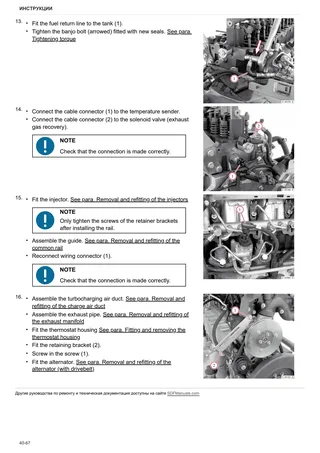
- Removal and refitting of the injectors
- Removal and refitting of the pressure cut-off valve
- Removal and refitting of the fuel pressure sensor
- Disassembly and assembly of the gear case cover
- Removal and refitting of the oil sump pan.
- Removal and refitting of the oil cooler
- Disassembly and assembly of the oil radiator housing
- Removal and refitting of the oil pressure switch
- Fitting and removing the fuel pressure regulator valve
- Removing and fitting the coolant pump (driven by toothed belt)
- Testing the thermostat (after removal)
- Removal and refitting of the thermostat
- Fitting and removing the thermostat housing
- Removing and refitting the torsional vibration damper (toothed belt drive)
- Removing and fitting the V-belt, V-belt pulley
- Removal and refitting of the flywheel
C0 – Комплектующие двигателя
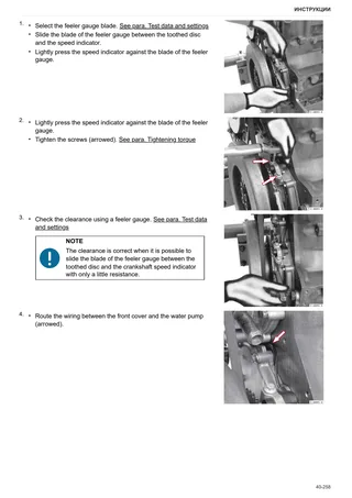
- Disassembly and assembly of the speed indicator (crankshaft)
- Removal and refitting of the camshaft speed sensor
- Removal and refitting of the exhaust manifold
- Fitting and removing the solenoid valve (exhaust gas recovery module)
- Removal and refitting of the fuel filter head.
- Removal and refitting of the rail pressure sensor
- Assembly and disassembly of the temperature sender
- Removal and refitting of the engine wiring loom
- Removal and refitting of the alternator (with drivebelt)
- Disassembly and assembly of the starter
- Removal and refitting of the supply air pressure/temperature sender
D0 – Трансмиссия
- Узел гидравлического реверса в сборе
- Блок реверса и HML
- Замена масла в трансмиссии
- Блок управления сцеплением
- Демонтаж привода сцепления
- Узел сцепления H
- Демонтаж узла сцепления H
- Пакет сцеплений медленных и средних скоростей
- Планетарный блок медленных и средних скоростей
- Распределитель управления коробкой Powershift
- Демонтаж распределителя управления узлом Powershift
- T.S78.21.D0.08.00.00.01
- T.S78.21.D0.07.00.00.01
- Приводной вал заднего ВОМ и насосная группа
- Передняя коробка передач
- Снятие передней коробки передач с задней
- Задняя коробка передач на стенде
- Крышка передней коробки передач
- T.S78.21.D0.09.06.00.02
- Нижняя крышка коробки передач
- T.S78.21.D0.10.00.00.01
- Демонтаж узла привода переключения диапазонов
- Блок переключения диапазонов и суперредуктор
- T.S78.23.D0.11.00.00.01
- Ведущая шестерня диапазонов
- Демонтаж ведущей шестерни диапазонов
- Ведущая шестерня переключения диапазонов скоростей
- Узел планетарного суперредуктора
- Демонтаж узла планетарного суперредуктора
- Сцепление включения ВОМ
- Выходной вал механизма отбора мощности (МОМ)
- Хвостовик вала механизма отбора мощности (МОМ)
- Вал и устройство включения двойного привода
E0 – Задний мост
- Задний мост
- Разборка заднего моста
- Регулировка подшипников задней полуоси
- Кронштейн тормоза
- Демонтаж водила сателлитов
- Задний дифференциал
- Демонтаж заднего дифференциала
- Узел торможения и тормозные диски заднего моста
- Демонтаж узла торможения и тормозных дисков заднего моста
- Исполнительные механизмы тормозов
- Rear brakes
- Регулировка блока EPB – Боуденовский трос
F0 – Передний мост
- Регулировка зазора между шестерней и зубчатым венцом
G0 – Кузов – Кабина – Платформа
- Механизм электрического тормоза Park brake
H0 – Гидравлическая система
- Узел насосов в сборе
- Приоритетный клапан
- Насос системы принудительной смазки тормозов
- Насос системы рулевого управления Powershift
- Перекачивающий насос
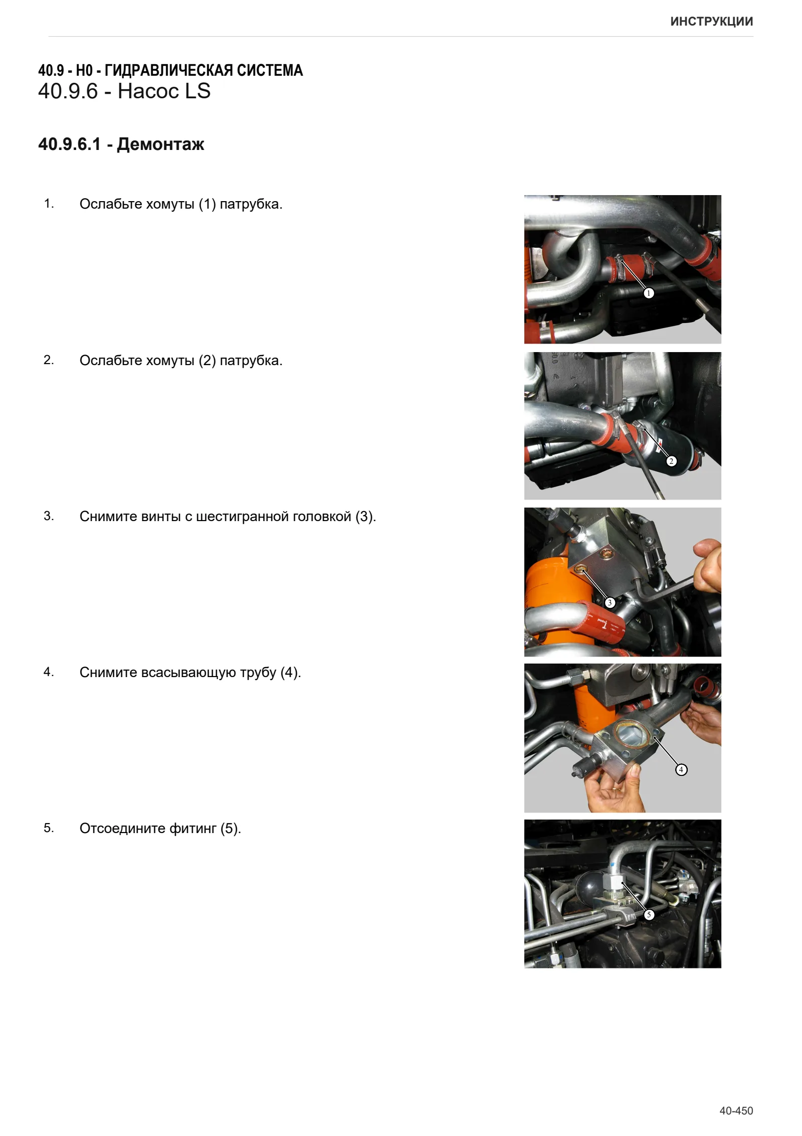
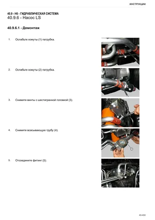
- Насос LS
L0 – Электрооборудование
- Датчик оборотов на выходе реверса
V1 – КОМПЛЕКТЫ ДООБОРУДОВАНИЯ
- Установка теплоизолирующих щитков
- Радиатор охлаждающей жидкости
Электросхемы
Введение
- Введение
- Понятия об электронике для механиков (1/2)
- Понятия об электронике для механиков (2/2)
- Электрические и электронные компоненты (1/2)
- Электрические и электронные компоненты (2/2)
Компоненты
- T.J59.01.L0.00.03.00.02
Оборудование
- S001 – Engine ECU
- S002 – Armrest
- S003 – Transmission ECU
- S004 – Services ECU
- S005 – Instrument panel (w/ hydraulic braking)
- S005 – Instrument panel (w/ air braking)
- S006 – Cab 1
- S007 – Cab 2
- S008 – Cab roof 1
- S009 – Cab roof 2
- S010 – Air conditioning
- T.J59.01.L0.10.01.00.01
- S012 – Positives
- S013 – Negatives 1
- S014 – Negatives 2
- S015 – Negatives 3
- S016 – Negatives 4
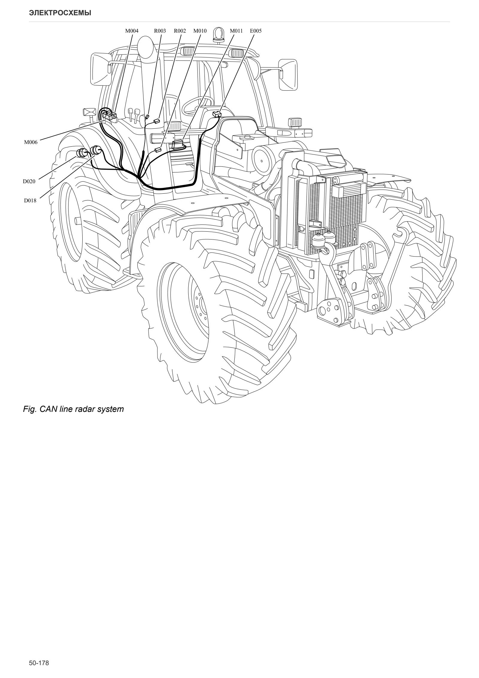
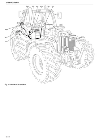
- S017 – CAN BUS
- T.S78.01.L0.10.06.00.01
Кабельные подключения
- 0.008.0913.3 – Front PTO wiring
- 0.010.8707.4/10 – SBA sensor lead
- 0.010.8711.4/30 – Rear lights wiring
- 0.011.3824.4/10 – Rotating beacon wiring
- 0.011.6007.3 – Water reservoir electric lead
- 0.013.4085.4/20 – Front lights wiring
- 0.013.4463.4 – Front axle suspension wiring
- 0.014.1645.4/10 – Hydraulic trailer braking wiring – Italy
- 0.015.2536.4 – Engine interface wiring
- T.J59.01.L0.00.02.02.06
- 0.016.0260.4/20 – Cab wiring
- 0.016.0261.4/20 – Front wiring
- 0.016.0262.4/10 – LH rear wiring
- 0.016.0263.4/10 – RH rear wiring
- 0.016.0264.4/10 – Battery leads
- 0.016.1001.4/20 – Trailer air braking solenoid valve wiring
- 0.016.1203.4/20 – Fuse box
- 0.016.1575.4/10 – Cab roof wiring
- 0.016.6592.4 – Brake wiring
- 0.016.8489.4 – Trailer air braking solenoid valve wiring
- 0.900.0783.8 – Air conditioning wiring
- 0421.4895 – Engine wiring
- T.S78.01.L0.02.02.00.01
- T.S78.01.L0.02.05.00.01
- T.S78.01.L0.02.05.00.02
Service Info
A0 – ТРАКТОР
- Diagnostics 2026 subscription
- After-sales 2026 subscription
- SERVICE NEWS RESEARCH GUIDE
- Diagnostics 2025 subscription
- After-sales 2025 subscription
- Diagnostics 2023 subscription
- Diagnostics 2024 subscription
- Diagnostics 2022 subscription
- Diagnostics 2021 subscription
- Technical Documentation DVD 06/2009
- Technical Documentation DVD 07/2008
- СМАЗОЧНЫЕ МАТЕРИАЛЫ SDF: Смазочные масла и охлаждающие жидкости
- After-sales 2024 subscription
- After-sales 2023 subscription
- After-sales 2022 subscription
- After-sales 2021 subscription
- After-sales 2019 subscription
- SDF Parts and SDF Service DVV 04/2014, version 26
- Technical Documentation DVD 03/2010
- Новая функция: Загрузка инструкций в формате PDF
- Диагностика – Абонемент 2020
- Послепродажное обслуживание – Абонемент 2020
- Послепродажное обслуживание – Canon 2018
- Услуги и Запасные части – Абонемент 2017
- DVD SDF Parts и SDF Service 05/2014 версия №25
- DVD SDF Parts и SDF Service 03/2013 версия №24
B0 – ДВИГАТЕЛЬ
- Flushing the lubrication circuit
- Deutz AG engine oil specifications
- SerDia 2010 обновления лицензионного файла
С0 – ДОПОЛНИТЕЛЬНЫЕ ПРИНАДЛЕЖНОСТИ ДВИГАТЕЛЯ
- Diagnostic protocol – AdBlue – Float level unit
- Filter and prefilter tool p/n 5.9035.865.0
- Additive for diesel fuel
D0 – ТРАНСМИССИЯ
- Retainer circlip of 4WD drive engagement mechanism
- Cracks in rear gearbox housing
F0 – ПЕРЕДНИЙ МОСТ
- Check the front axle steering knuckles for wear
- Steering behavior check procedure
G0 – КУЗОВ – КАБИНА
- Air conditioning system recharging
H0 – ГИДРАВЛИЧЕСКАЯ И ПНЕВМАТИЧЕСКАЯ СИСТЕМА
- Hydraulic CUNA trailer braking kit (ITALY)
- Single connection hydraulic braking kit availability update – only for EUROPEAN market
- Resonator failure
- Assembly instructions for solenoid valves and cartridge valves
- L0 – ЭЛЕКТРООБОРУДОВАНИЕ