

Document overview
Digital Workshop Manual documentation for model SAME FRUTTETO 80.4 NATURAL → ZKDEZ70200RS50001 from the FRUTTETO NATURAL (FARMOTION STAGE 3B) family. Language: English; 909 pages.
The corresponding English table of contents contains 46 sections and 330 individual topics.
Main sections included
- Introduction
- Safety
- Technical characteristics
- Calibrations and electronic diagnosis
- Method of intervention
- Wiring diagrams
- Service Info
Document details
- Brand: SAME
- Family: FRUTTETO NATURAL (FARMOTION STAGE 3B)
- Model: FRUTTETO 80.4 NATURAL
- Starting serial number: ZKDEZ70200RS50001
- Document type: Workshop Manual
- Language: English
- Pages: 909
- File size: 233.19 MiB
- Format: Digital PDF download
Compatibility
Before purchasing, verify that your machine model and reference code match SAME FRUTTETO 80.4 NATURAL → ZKDEZ70200RS50001.
Complete table of contents
Introduction
- Tightening Torques
- Pump tightening torques
- Wheel rim to hub screws and nuts tightening torques
- Tightening torques for nuts and bolts of electrical connections
- Installation of solenoid valves and cartridge valves
- Installation of quick couplers
- Units of measurement and conversion factors
Safety
Preface
- Important notes concerning safety
Important safety information
- Recognising hazards
- Indications for persons in contact with the tractor
Safety rules
- Risks during tractor preparation
- Risks during maintenance
- Work on machine systems
- Special disassembly/assembly/inspection procedures
Safety pictograms
- Replacing safety pictograms
Environmental risks
- Hazards associated with the operating environment
Technical characteristics
Engine
- Technical data: cylinder block
- Technical data: crankshaft
- Technical data: pistons – piston rings
- Technical data: rockers
- Camshaft technical data
- Technical data: timing system gears
- Technical data: counter-rotating masses
- Technical data and dimensions: valves – valve springs
- Technical data and dimensions: heads – valve guides – valve seats
- Technical data, rockers – tappets
Engine accessories
- Starter motor
Transmission
- Transmission
- Connector housing
- Gearbox and shuttle assembly
- Range gearbox and parking brake assembly
- Four-wheel drive engagement assembly
- Rear PTO
Rear axle
- Brakes and rear axle assembly
- Differential unit
Front axle
- 4WD front axle
- Pinion, differential and differential lock
- Final drive
Hydraulic system
- Hydraulic System
- Braking system
- LH 8 cc hydraulic pump
- RH 19 cc hydraulic pump
- 4WD steering control valve
- 4-way remote control valve
- 6-way auxiliary control valve
- FARMotion engine sensors and components
Rear lift
- Rear lift
Calibrations and electronic diagnosis
- ECUs
Diagnostic tools
- D-Tech and diagnostic ports
- D-TECH App
Commissioning and calibrating the tractor
- Commissioning procedure (EOL)
- Cluster configuration
- Optionals setup
ECU alarms
- SDF Severity of alarms
- ECU ALARMS
Software management
- ECUs firmware update
- Download Dataset FARMotion & Flash ECU
Method of intervention
B0 – Engine
- Workshop tools for engine removal and reassembly
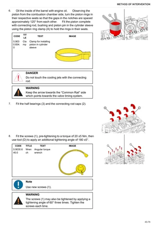
- Tightening procedure for engine components
- Complete engine
- Engine- Separation from the transmission
- Preliminary operations before removing engine from vehicle
- Engine flywheel
- Engine-transmission mating flange
- Blow-by oil vapour recovery pipe
- Turbocharger oil pipes
- Turbocharger
- EGR exhaust gas recirculation pipe
- Exhaust manifold
- Thermostat valve
- Checking the thermostat valve
- EGR exhaust gas cooling pipes
- EGR manifold
- Disassembly of the EGR manifold
- EGR valve
- Blow-by filter
- Coolant manifold
- Intake manifold
- Oil filter
- Oil heat exchanger
- Engine coolant pump
- Electro-injectors and common rail
- Cylinder head covers
- Blow-by oil vapour pipe
- Pushrods
- Cylinder heads
- Disassembling the cylinder heads
- Crankshaft pulley and tone wheel
- Crankshaft pulley
- Power take off drive
- Front timing cover
- Rear flange
- Oil sump
- Oil pump
- Counter-rotating masses
- Overhauling counter-rotating masses
- Intermediate gear and timing
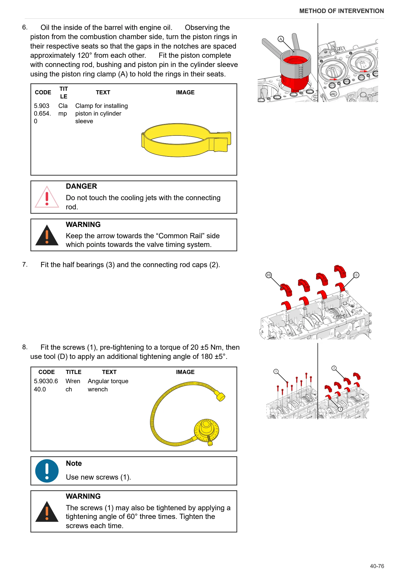
- Disassembling pistons and connecting rods
- Crankshaft
- Cooling jets
- Cylinder sleeves
- Adjusting oil pump gear backlash
- Installing automatic belt tensioner
- Aligning water pump and crankshaft pulleys
- Water pump / alternator belt
C0 – Engine accessories
- Replacing the coolant
- Engine air intake fan
- High pressure fuel pump
- Water radiator
- Compensation tank
- Mounting brackets
- Air filter
- Intercooler
- Diesel radiator
- Fuel filter
- Fuel prefilter
- Bleeding the fuel circuit
- Diesel fuel tank
- Electric starter motor
- Exhaust pipe
- Exhaust silencer – Catalytic converter (DOC)
- Power take off gear backlash adjustment
D0 – Transmission
- Changing the transmission oil
- Complete gearbox assembly
- Front gearbox from its rear part
- Clutch assembly
- Clutch plate wear check
- Thrust plate assembly
- Disassembling the gearbox input shaft
- Disassembly of the main shaft
- Disassembling the secondary shaft
- Adjustment of end float on secondary shaft gears
- Range selector rod
- Disassembly of dual traction output shaft
- Adjusting the bevel gear set
- PTO input shaft
- PTO output shaft (2 speed version and groundspeed version)
- PTO output shaft
- Ground speed PTO shaft
- Replace the parking brake wear shoes
- Disassembling the parking brake lever
- Adjusting the parking brake lever
- Internal range reduction gear controls
- Rear pinion
- Range reduction gearbox shaft
- 4WD engagement device
- 4WD output shaft in transmission.
- Hydraulic pump drive
- Disassembling the power steering pump and ancillary pump carrier
- Adjusting power steering pump and ancillary pump carrier gear free play
E0 – Rear axle
- Bleeding the braking system
- Rear axle
- Removing right/left hand rear axle
- Disassembling the planetary gear unit
- Rear differential
- Rear differential lock control fork
- Removing the rear differential
- Brake carriers
- Replacing the friction shoes
F0 – Front axle
- 4WD shaft
- Support with front axle
- Front axle (4WD)
- Steering cylinders
- Disassembling the steering cylinder
- Pinion-differential assembly
- Disassembling the front axle differential – Complete assembly
- Adjustment of the differential preload
- Adjusting pinion position
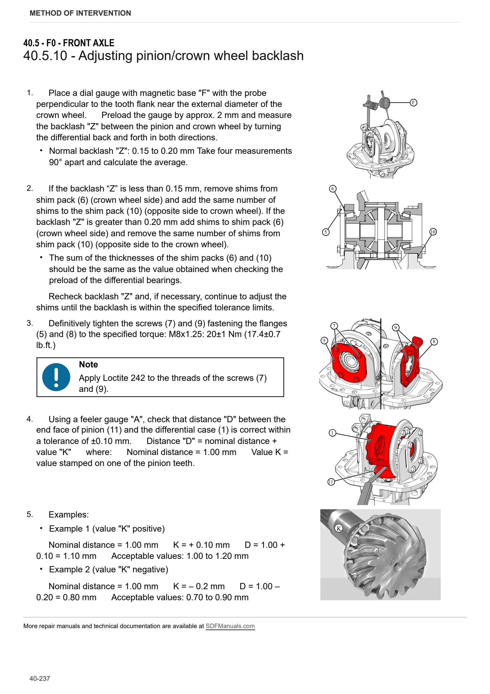
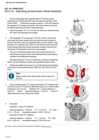
- Adjusting pinion/crown wheel backlash
- Adjusting pinion bearing preload
- Disassembling the bevel gear set
- Adjusting front axle endfloat
- Differential lock
- Differential lock device adjustment
- Planetary reduction gearbox
- Disassembly of the planetary reduction gearbox
- Complete steering knuckle housing
- Adjusting bearing preload
- Front brake discs
- Front axle brake piston
G0 – Bodywork – Cab – Platform
- Engine hood and front hood panels
- Lower hood guard
- Pedal board mount
- Battery mount
- Access ladder
- Rear mudguard
- Right and left hand mat and footboards
- Instrument cluster
- Instrument cluster
- Seat
- Seat controls mount
- Disassembling the electronic throttle control pedal
- Clutch pedal
- Brake pedals
- Steering column
- Electronic throttle pedal control sensor
- Steering wheel
- Brake master cylinders
- Rear lift control levers
- Disassembly of the rear hitch control tie-rods
- Adjusting lift control levers
- Roll bar and mounts
- Rear roll bar
H0 – Hydraulic system
- Ancillary pump
- Power steering pump
- Hydrostatic steering (orbitrol)
- Rear auxiliary distributor
- Disassembling the rear ancillary utility distributor
- Brake block
L0 – Electrical system
- Battery
- Alternator
- Electronic engine control unit
- Hand throttle sensor
- Air filter clogging pressure switch
- Clutch control switch
- Brake control switch
- PTO switches
- Engine wiring loom
- Charge pressure and air temperature sensor
- Electro-injector wiring loom
- Coolant temperature sensor
- Crankshaft speed sensor
- Preheat relay
- Camshaft timing sensor
- Engine oil pressure switch
- Engine oil temperature sensor
- Fuel pressure and temperature sensor
- Fuel pressure sensor
- Water in fuel sensor
R0 – Rear lift
- Complete lift
- Rear lift – Complete assembly
- Replacing bushes
- Hitch control distributor
- Disassembling the lift control distributor
- Mechanical draft sensor
- Mechanical draft sensor disassembly
- Disassembling the lift cylinder
- 3-point linkage
S0 – Wheels
- Front Wheels
- Rear wheel
V0 – Ballast – towing hitches
- Tow hook sled
- Drawbar
Wiring diagrams
Introduction
- Introduction
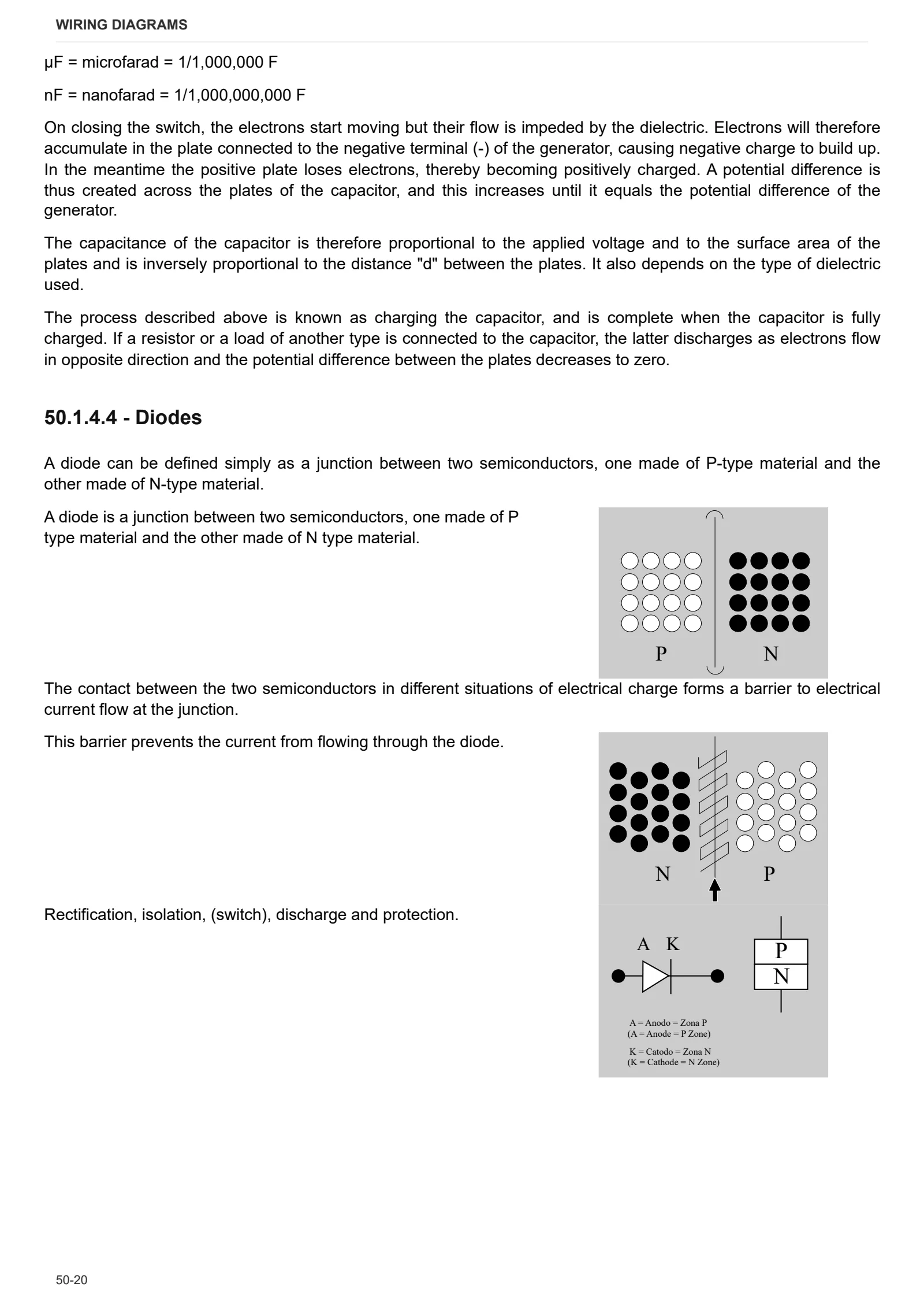
- Basic electronics for mechanics (1/2)
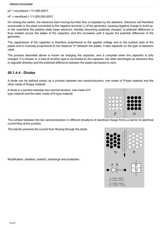
- Basic electronics for mechanics (2/2)
- Electrical and electronic components (1/2)
- Electrical and electronic components (2/2)
Components
- 2.8519.151.0 – Engine ECU
- A – Starting and charging
- B – Fuses
- C – Grounds
- D – Intermediate connections
- E – On-board instruments and visual and audible indicators
- F – External lights (rotating beacon)
- H – Manual electrical controls (steering column stalk)
- I – Circuit breakers
- J – Relays
- K – Sensors and transmitters
- L – Electromagnets and solenoid valves
- M – Electrical/electronic devices, Flasher units and Timers
- N – Electric motors and actuators
- O – Resistors and rheostats
- P – Various services
- R – Diagnostics
Systems
- S001 – Electronic engine throttle
- S002 – Preheating
- S003 – Activation and charging
- S004 – Lights
- S005 – CAN line and diagnostics
- S006 – Instrument cluster
Wiring harnesses
- Wire colour reference table
- 0.011.7840.4 – Rotating beacon
- 0.021.1217.4 – Heater
- 0.021.3289.4/10 – Rotating beacon socket
- Rear lights
- 0.021.3292.4 – Front lights
- 0.022.3240.4 – Trailer braking pressure switch
- 0.023.1279.4/20 – Engine – 3 cylinder version
- 0.023.1280.4/20 – Engine – 4 cylinder version
- 0.023.1281.4 – Injectors – 3 cylinder version
- 0.023.1282.4 – Injectors – 4 cylinder version
- 0.026.5156.4 – Alternator – preheat
- 0.026.5162.4 – Throttle pedal
- 0.027.5708.4/10 – Battery cables (3 cylinder version)
- 0.027.5709.4/10 – Battery cables (4 cylinder version)
- 0.027.5710.4 – Front 3 cylinder version
- 0.027.5711.4 – Front – 4 cylinder version
- 0.027.5712.4/10 – Central wiring loom
- 0.027.5713.4 – Rear wiring loom
- 0.027.5716.4 – Battery master switch ground
- 0.027.5717.4 – Engine ECU power supply
- Hydraulic trailer braking
- Front lights and horn
- 0.027.5724.4 – License plate light
Service Info
A0 – TRACTOR
- Diagnostics 2026 subscription
- After-sales 2026 subscription
- SERVICE NEWS RESEARCH GUIDE
- Diagnostics 2025 subscription
- After-sales 2025 subscription
- Diagnostics 2023 subscription
- Diagnostics 2024 subscription
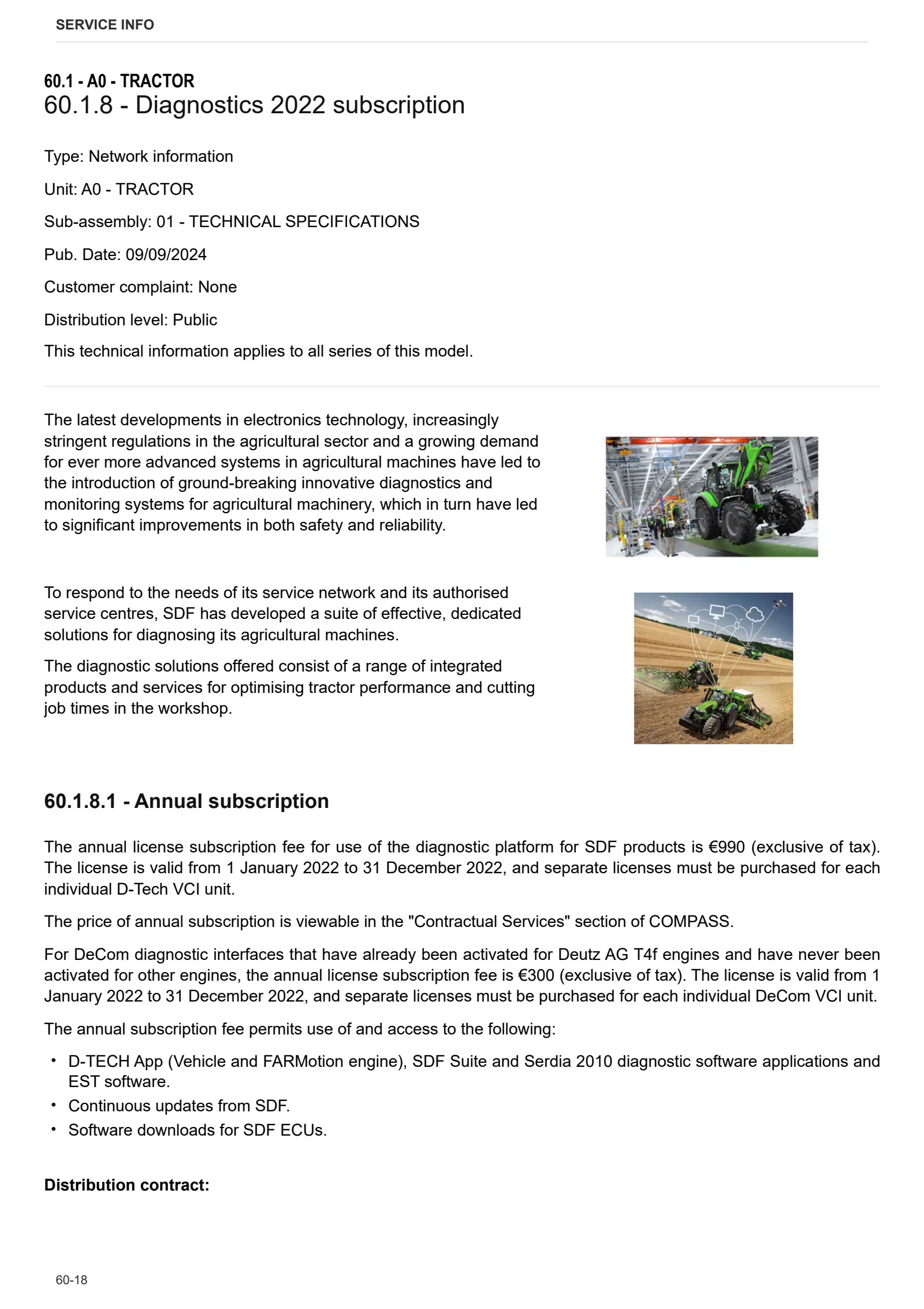
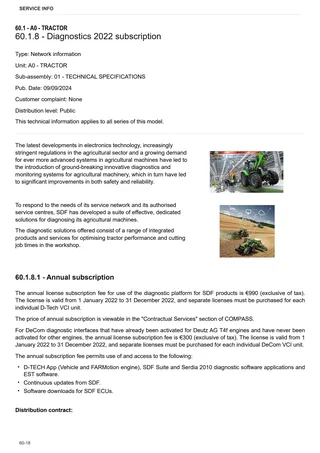
- Diagnostics 2022 subscription
- Diagnostics 2021 subscription
- After-sales 2024 subscription
- After-sales 2023 subscription
- After-sales 2022 subscription
- After-sales 2021 subscription
- After-sales 2019 subscription
- Diagnostics – 2020 subscription
- After-sales – 2020 subscription
- After-sales – 2018 subscription
B0 – ENGINE
- Leakage from turbo inlet oil pipe
- FARMotion seal ring leakage
- Deutz AG engine oil specifications
- Engine sealing ring leakage
C0 – ENGINE ACCESSORIES
- Diagnostic protocol – AdBlue – Float level unit
- Filter and prefilter tool p/n 5.9035.865.0
- SCR AREA DAMAGED SENSORS
D0 – TRANSMISSION
- Double Clutch Failure
F0 – FRONT AXLE
- Bevel gear set loosing screws
- Front Axle Bearing damage on slope condition
- Check the front axle steering knuckles for wear
- Steering behavior check procedure
G0 – BODYWORK – CAB
- SERVICE NEWS – Brake Fluid Reservoir vent missing
- Air conditioning system recharging
- No pressure at hydraulic trailer brake valve
- Contact between handbrake fork and filter tank
- Knob cracking
H0 – HYDRAULIC AND PNEUMATIC SYSTEM|
- Hydraulic CUNA trailer braking kit (ITALY)
- Single connection hydraulic braking kit availability update – only for EUROPEAN market
- L0 – ELECTRIC AL SYSTEM